When you click on links to various merchants on this site and make a purchase, this can result in this site earning a commission. Affiliate programs and affiliations include, but are not limited to, the eBay Partner Network.
For those w/ experience &/or running lighter flywheels ...what are your opinions / thoughts pro or con for running a lighter fly-wheel in ... albeit a spirited ..., but somewhat DD (I work from home)?
I bought the BHR flywheel second hand, and it's been about a year now with it on. I changed the clutch out with the "stock" Exedy stage 1 so clutch resistance feels the same to me. You just have to slip it on the engagement point and it'll be a smooth ride. I will say the steeper the incline you stop on, the more you'll have to slip it to get it going. I'm NA, and it does yield some noticeable acceleration difference, especially in 2nd gear. With a turbo, I suppose it might indirectly help build spool faster in relation to time.
... I won’t fuss over it any more than I already did, but disagree that you can just size up different wheel sizes to compare one manufacturers turbo to the map of another. Then trying to use those efficiency points to me suggests a lack of understanding.
.
I agree ... and have already conceded as much: I'd much prefer to *design forward* w/ the aid of a comp. map. However, in this case ...as is sometimes advantageous in life ...we make decisions and proceed with less than ideal information. The inability to precisely predict an outcome ...doesn't guarantee a bad one. Often other factors in play.
For the life of me I don't understand why Precision doesn't distribute maps , and while a poor marketing decision...it doesn't negate that their product c/b a good "value". I have had no issue w/my 6266, and am well aware that others Mfgs provide more bells & whistles ...for a premium.
Originally Posted by TeamRX8
... Just out of curiosity, did you give any consideration to hacking off the Precision v-band & replace it to use a Garrett G-series turbo instead?
I used to run a lightweight flywheel on my old Greddy setup. What I noticed was I would spin the tyres in 2nd gear .............a lot. At the time I thought it was the LWFW but later realised it was just that back then I ran cheap tyres. So .............just another argument for gaining hard data for any mod. that's done vs the ole butt dyno.
OE is ~16.8 lbs (per Racing Beat) but that includes an integral CW. The auto-trans CW that an aftermarket flywheel requires is 3.6 lbs.
So all you’ll get for mass reduction is 13.2 lbs - X.X lbs of the aftermarket flywheel. It’s just not that much mass compared to OE flywheels that weigh 30+ lbs. The OE flywheel is lighter than some FC/FD RX7 aftermarket flywheels w/CW even. The lightest standard clutch RX8 flywheel that I’m aware of is the Racing Beat aluminum at 8 lbs. So you’ll only drop around 5 lbs and that’s practically nothing against turbo output not likely to rev much to or past 8000 rpm.
EDIT: Well, still coming up to speed on interpreting compressor maps... so l'll keep this simple. Some trends appear evident when comparing the below three compressor maps:
Lol, interesting ...just trying to learn and share as I go/grow, and to that point ...have learned a good deal studying the maps ...regardless how accurate the projection.
So, do you think this not worth the exercise given the use of "comparable" maps..., or that incorrect assessments h/b made?
both, would prefer to see someone choose a more certain outcome over compounding assumption upon assumption:
but what God closes, no man can open … 🤨 .
Well, I definitely agree the G25-660 and G30-660 turbos are better, i.e. near perfect in all respects, for the Renesis, and what I w/h chosen had I wanted to spend the add'l $$.
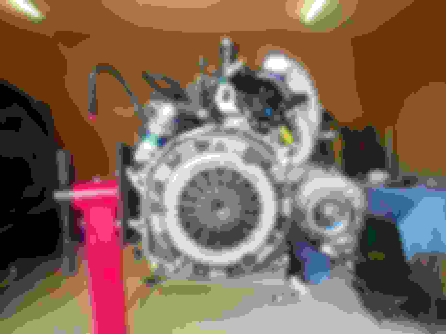
Made good progress on the reinstall today:
- installed the turbo oil feed & drain
- Finished turbo clocking and mounting for reinstall
- Installed oil filter pedestal and cooler line
- installed engine in bay (rarely easy ...smh)
Next up:
- dressing the engine bay
- reinstalling the down pipe & WG
- noodling ideas to transition from my 8" back to my 12" IC, ... mounting it high enough to allow adequate ambient airflow underneath to the rad, w/out completely frankensteining my crash bar.
I've run a few different IC configurations hoping to find an optimial balance between IAT and ECT performance.
- 1st config: 12", FMIC config (w/ 13 cooling rows open to ambient flow)
- 2nd config: 12", reverse v-mount config w/ splitter (w/ 17 cooling rows open to ambient flow, but laid flat)
- 3rd config: 8, FMIC config ( w/ 12 cooling rows open to ambient flow)
New / current config: 12", FMIC config (w/ 17 cooling rows open to ambient flow).
The IC w/b mounted as high as possible to allow as much air flow underneath the IC directly to the rad as possible. I anticipate good IATs, but ECTs w/ this config are TBD.
Intercooler config evolution:
1st config. 12" (w/ 13 cooling rows open to ambient flow)
.
2nd config 12" (w/ 17 cooling rows horizontal to ambient flow, in reverse v-mount config w/ splitter) .
3rd config. 8" ( w/ 12 cooling rows open to ambient flow)
.
New / Current config. 12" IC, (w/ 17 cooling rows directly open to ambient flow.)
.
Nice work showing all those Curtis. Care to show some numbers and comments about success or otherwise of each iteration?
I've gone through a similar learning curve leading to my latest setup.
Nice work showing all those Curtis. Care to show some numbers and comments about success or otherwise of each iteration
I've gone through a similar learning curve leading to my latest setup.
Sure thing. I'll pull together some data & observations on each.
Progress update:
Continued steady progress, but discovered an issue as well.
Installed:
- Down pipe
- WG (w/ 1.5# initial break-in spring)
- AC Compressor
- Plugs, Ignition coils & harness
- Successfully pressure tested the fuel injectors and rails
However, when inspecting couplers I discovered an issue I need to resolve with my passenger motor mount bracket. This is not "new" ... I just didn't deal with it, , , when first discovered back in 2018.
Edit: The bracket is at the machine shop. The horizontal is being lowered 0.5" on the vertical to create clearance for the comp. inlet coupler. I'll shim the driver side motor mount an equal amount to keep things leveled off, if req'd.
v
v Current Status of bay...
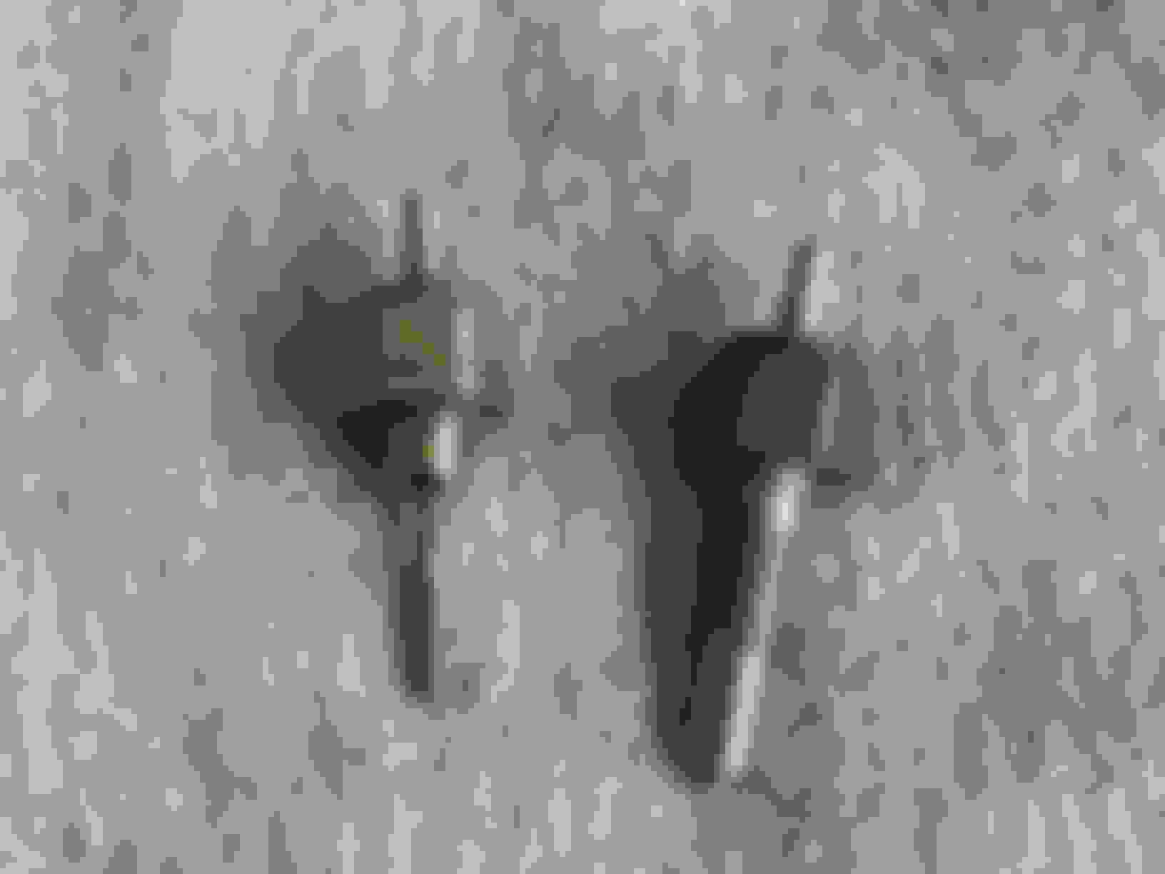
. Passenger Motor Mount bracket issue: does not provide enough clearance for comp. inlet coupler.
. Pic w/ pinched coupler from 2018 when first noticed
. ...resultant coupler today.
I can assure you that it’s not me who isn’t seeing it for what it is, but saved for another day.
All I mean by that is it’s still based on the OE type design and I’m well familiar with what you have. It likely won’t click until observed with a fleshly eye …
.
 06-01-2021, 01:40 PM


 , and while a poor marketing decision...it doesn't negate that their product c/b a good "value". I have had no issue w/my 6266, and am well aware that others Mfgs provide more bells & whistles ...for a premium.
 . Truth.


 , , when first discovered back in 2018.