When you click on links to various merchants on this site and make a purchase, this can result in this site earning a commission. Affiliate programs and affiliations include, but are not limited to, the eBay Partner Network.
With engine off, and ignition on , put enough pressure down the signal line to trigger the controller. Solenoid should start cycling.
Fault find from there.
With engine off, and ignition on , put enough pressure down the signal line to trigger the controller. Solenoid should start cycling.
Fault find from there.
I've no reason to suspect the control line integrity at the WG...as 3-port solenoid was working fine.
Will confirm today that air is properly diverted from bottom to top port ...when modulated under Greddy command. If that checks out......what next....EBC settings?
My guess is , whatever the problem was before is still there and has been exacerbated.
I'd be pulling the WG to inspect it and checking BOV.
Brett, Thx. I've pulled & checked the WG recently ...when swapping springs ...when I was running the M2 control method; and didn't find any sticking, binding, torn diaphragm, etc.
If the BOV were stuck closed....I'd see overboosting, which I'm not seeing. If... stuck open, I'd experience underboosting, which I am. But not laggy boost build-up and underboost. Just inability to generate boost above WG spring #. And I was not seeing laggy spool response, or underboosting of this type... when running the 3-port solenoid.
I'm going to try more dialing in the EBC settings...b/c this isn't making sense.
agreed!
When crap like this happens you really have to go deep into how everything works and figure out how to test that every item that can influence it is doing what it should.
Well,...full disclosure...in my exasperation I swapped the 3-port back in, ... went for a spin expecting that 13+ psi jet feeling. Nada,...no love...8 psi . 🤣.....🤨.....😢. Something's changed. She's put away... in time out...at least until the long weekend.
As you suggest...plan to throw her on stands, and check all the control lines and hardware.
Exhaust manifold leak? I've had similar symptoms when the wastegate v-band wasn't seated correctly - no exhaust leak noise at idle, just real laggy and lower boost than expected.
Exhaust manifold leak? I've had similar symptoms when the wastegate v-band wasn't seated correctly - no exhaust leak noise at idle, just real laggy and lower boost than expected.
Jimmy, Thanks. I hope it's not an exhaust mani leak. A poor WG v-band seal wouldn't be too bad. I'll check tomorrow.
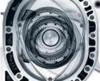
Pulled the WG, and found the culprit: evidently the spring was in slightly angled...causing the plunger to rub/ catch against the v-band inner ring seal. Everything else checked out.
She's boosting about normally again. 4-port solenoid is going back in.
Couple pics:
- 1st pic: you can see the trace of the spring grinding into the inner WG base wall (riding up diagonally) .
- 2nd pic: ...where the plunger was "catching" on the inner side of the v-band ring.
Originally Posted by Brettus
... I'd be pulling the WG to inspect it and checking BOV.
I was still seeing boost drop to spring pressure occasionally...in certain situations. Additionally, I've gained confidence that my system can run a bit more boost ...safely and before needing to further upgrade injectors. Since I couldn't get the 4-port solenoid to work properly... , and rather than purchase a boost by gear EBC ... @ $300+, I decided to try a hybrid WG control method to both resolve the boost dropping, and raise boost to ~14 psi.
Four pressures act on the WG: two on the bottom, ...two on the top. Top: (spring) + (EBC modulated) Bottom:(boost line pressure) + (back-pressure)
Theoretically, by attenuating the "boost line pressure", the WG c/b held closed to a higher system pressure ...w/out installing a larger spring.
So, I installed a MBC ($45) in the WG bottom port boost line, and attenuated the boost ~30%.
Post change estimated system pressures: Top: (9# spring) + (13 psi, EBC modulated) = 22# Bottom: (9 psi, MBC Adjustable) + (~9 psi back-pressure) = 18#
Therefore, giving "EBC Control" 4 additional psi "headroom" to modulate for higher system boost ...before the WG opens.
Initial tests are positive: no dropping out, ...14.x psi w/ ease, and no identified drawbacks as yet. Still tuning to bring it down to lower 14's psi, but fairly close to "done".
I plan to swap in a 6# spring w/ this method ...which should have no issue still reaching low 14's psi peak.
Where'd you get the 9psi backpressure figure from? I'd expect this figure to be >20psi at redline. The small amount of experimenting and reading I've done suggests it would usually be 1.5 to 3 times boost pressure at redline.
Where'd you get the 9psi backpressure figure from? I'd expect this figure to be >20psi at redline. The small amount of experimenting and reading I've done suggests it would usually be 1.5 to 3 times boost pressure at redline.
Good question. It really was deduced from the working of things. Back pressure is dynamic relative to boost, and I make the assumption that it c/b represented as ...[back pressure = boost x coefficient], so that b-pressure increases as a factor of boost.
I also considered that WG operation as described above was entirely controlled by four pressures: Top: (spring + EBC boost)
Bott: (control line boost) + b-pressure).
In my system the WG was being forced open, i.e. boost dropping to spring pressure, reliably at ~ 13.5 psi. I presumed two things were true at this point:
1. The EBC was passing on all available boost through the solenoid to the top of the WG, 13.5 psi, in this case.
2. This point represented equilibrium, i.e. the point at which the pressures acting on the bottom just exceed those acting on the top.
Then, setting top forces equalto bottom yields: (9# + 13.5 psi) = 13.5 psi + back pressure). Solving this identifies back pressure of ~ 9 psi, i.e. boost x a coefficient of 0.67: 13.5 x 0.67. Now in reality the solenoid c/b passing along something less than current boost, 13.5 psi, in which case you w/b right that back pressure is higher e.g. (9# + 13.5 psi) = 10 psi + back pressure). Then back pressure w/b 12.5 psi. The actual back pressure is less important ...than the fact that the sum of control line boost and back pressure equal forces acting on the top of the WG at this point.
Realizing this...and the fact that the EBC can't "create" boost, but only modulate the boost which exists; then I realized that by attenuating the "control line boost" I could create an imbalance in my favor ...so that the EBC could, using the boost available to it, maintain greater force on the top of the WG than was present on the bottom.
Ex. If the control line boost is attenuated by 10% then the equation becomes: Top: (9# + 13.5 psi) = 22.5 Bott.: (12.15 psi + 9 psi) = 21.15
...and in this scenario the EBC will have an added psi "range" to modulate existing boost to keep the WG clamped shut.
In this case boost c/b raised to 15.75 psi before WG bottom pressures will equal those on the top...and force the WG open: control line = 15.75 x 0.9 = 14.18 psi back pressure = 15.75 x .67 = 10.55 psi
So, by attenuating the control line boost 10%, system boost c/b theoretically raised from 13.5 to 15.75 psi.
*Note:
1. The #s are estimates...I was more concerned w/ the theory that this hybrid WG control could enable the system to achieve higher system pressure w/out installing a larger spring.
2. I only pursued this b/c I couldn't get my 4 port solenoid to work...which is the preferred method to which I will likely revert at some point. But thought I'd share...b/c it works.
Update: Completed some minor tidy work: resolving a leak at the oil pan turbo drain bung...
. Ready for re-installation...
On another note I believe my Pineapple oil pan gasket is leaking. . Was hoping to be done w/ pulling and reinstalling this oil pan, but...looks like it's coming off again and getting re-installed w/ old faithful: gray Permatex.
Good question. It really was deduced from the working of things..
At 14psi boost pressure with your setup, backpressure will definitely be over 20psi at peak rpm... You really should be measuring this now that you are experimenting with elevated boost.
The diameter of the wastegate valve that sees backpressure is maybe 42mm ish . Whereas the diameter of the diaphragm inside the WG housing will be more like 60mm . Just a guess there, but my point is, that needs to be in your calcs.
Fair points ...on both accounts.
- You have mentioned before...and rightly so...I s/b measuring back pressure. I will get this done ...at some point.
- And yes, you're also right ...the diameters of the surface areas the pressures are acting on w/in the WG will definitely have an impact, and s/b included in the equation. That would explain why my estimated back pressure is off ...as Jimmy also pointed out.
Thanks, Jimmy & Brett, I'll get those diameters, revise the equation, and see what results.
perhaps it should be clarified as either total pressure or differential pressure. Because I’ not entirely sure which you mean.
T, Not sure what you mean by differential pressure. But fair enough...I am addressing boost from a number of differing sources. I try to identify each pressure by it's source:
EBC pressure: EBC modulated pressure Control line pressure: This is the WG boost/ pressure control line tapped directly off the charge section. Therefore, the "actual" system boost at the point in time. Back pressure: Back pressure as seen at / by the WG MBC pressure: This is the "Control line pressure" after attenuation by the MBC.
Might just be my misunderstanding because I’d prefer to use the term differential pressure rather than back pressure. What are you defining as B-P at the wastegate then; pre-turbo manifold pressure - post turbo exhaust pressure?
I was actually trying to figure out what Brettus meant with the 20psi reply because of the terminology. There is total manifold pressure and the differential pressure between it and boost pressure and then also the differential pressure between it and the exhaust pressure. I had his name in the reply, but reworded it and left that out. Sorry for the misunderstanding.
Might just be my misunderstanding because I’d prefer to use the term differential pressure rather than back pressure. What are you defining as B-P at the wastegate then; pre-turbo manifold pressure - post turbo exhaust pressure?
...There is total manifold pressure and the differential pressure between it and boost pressure and then also the differential pressure between it and the exhaust pressure.....
Right on...excellent point. I'm referring to the force directly acting on the WG valve, which I believe to be pre-turbo exhaust manifold pressure. So, I was incorrect in labeling it back-pressure.
I'm not sure how the differential pressures you describe come into play.
My understanding is that the term 'differential pressure' implies you are looking at the difference between two pressures.
The term 'Turbine Back pressure' is used quite commonly to describe the exhaust manifold pressure or EMAP.
If you were referring to pressure post turbine you would call it 'exhaust backpressure'.
Edit: In this post when I state "backpressure", I'm talking EMAP, not turbine back pressure.
"Boost" is cold side pressure, "Backpressure" is hot side pressure in PSI above atmospheric. The backpressure is the pressure of the hot exhaust gas in the exhaust manifold trying to press the wastegate open, acting against the force of the WG spring.
Brettus and I started measuring back pressure on our respective setups around the same time to guide us towards more efficient turbo setups. You can reduce exhaust backpressure by improving exhaust flow after the turbo and/or wastegate, by changing the turbo wheels and housings, and reducing pressure drop the coldside across piping and inter cooler (sometimes at the expense of spool). Any modification that reduces backpressure while keeping the boost level at the same value will result in the engine flowing more air (I.e. more power). The trick is to lower back pressure ratio without losing spool. You can see on Brettus' new exhaust manifold that there are small pressure signal lines tapped into the front and rear sections of his manifold. These lines are each connected to boost sensors/gauges and used to measure the exhaust pressure as seen by front and rear sections of the manifold (I.e. front and rear scrolls of the turbo). If you can capture these front and rear exhaust back pressures (hot side) along with boost pressure (cold side) and rpm and mass airflow, you can measure conclusively whether each change to the turbo setup is an improvement on efficiency of the turbo setup. Of course, on most rx-8 turbo setups the front and rear runners of the exhaust manifold are joined, so one pressure line is sufficient. When Brettus made the decision to reduce turbine housing AR on his setup, this may seem counter-intuitive, but it was guided by the front and rear exhaust back pressure readings he had logged, and it resulted in a more efficient setup. Correct me if I'm wrong here Brett!
Edit: Here's a link to my back pressure experimentation. I installed the sensor, recorded some results, upgraded the turbo, then recorded more results to compare old and new turbo. This was all on a Greddy manifold (t25 turbine flange). https://www.rx8club.com/series-i-maj...3/#post4730979
Last edited by JimmyBlack; 09-23-2020 at 11:15 PM.
Reason: Added link to relevant content.
Not trying to make an argument, but the terms used on BW’s Matchbot are; intercooler pressure drop, exhaust back pressure, manifold pressure, engine differential pressure. There are potentially more than that. Note that they all have a reference though.
Because the only point is there are multiple back-pressures depending on where you’re referring to and how you’re looking at it. Without a reference on which one it was, I wasn’t sure. Because with a 14 psi boost and 20 psi manifold pressure it could be said that there’s 6 psi back-pressure, which is the engine differential term used in matchbot. Which that 6 psi differential figure is also going to include exhaust back-pressure. Somebody else might interpret that as 34 psi manifold pressure thinking 20 psi back-pressure was the differential. Like a lot of other things people seem to disagree with me on, not really sure why you wouldn’t just called it what it is; manifold pressure.
With that size turbine at that output though, I was thinking it’d be less than 6 psi, but that might depend on the exhaust.


 09-02-2020, 09:39 AM
 . 🤣.....🤨.....😢. Something's changed. She's put away... in time out...at least until the long weekend.
 4-port solenoid is going back in.


 , and rather than purchase a boost by gear EBC ... @ $300+, I decided to try a hybrid WG control method to both resolve the boost dropping, and raise boost to ~14 psi.


 . Was hoping to be done w/ pulling and reinstalling this oil pan, but...looks like it's coming off again and getting re-installed w/ old faithful: gray Permatex.