When you click on links to various merchants on this site and make a purchase, this can result in this site earning a commission. Affiliate programs and affiliations include, but are not limited to, the eBay Partner Network.
I was reviewing, purging, etc. docs I've compiled along the way. I'm going to post this drawing that I created early in my installation planning phase here. It helped in my comprehensive system understanding, as well as managing the details, e.g. BOM, vac lines, connectors. layout, etc. for my install.
Credit to JimmyBlack who I got the idea from after seeing a similar drawing in his thread, Jimmy's First Turbo Build. I find well thought diagrams of complex systems aid in my understanding and managing them. Perhaps others will find this useful as well.
.
.
Cool drawing Curtis ! Couple of minor changes and I could use that to help guys for new tunes.
1/looks like you are getting air for the wastegate from the exhaust the way you drew it.
2/would be good to include check valves on jet air and omp lines
3/Signal line for ebc shouldn't be post throttle (my personal preference)
Thanks, Brett.
1/looks like you are getting air for the wastegate from the exhaust the way you drew it.
- Curt: The control line for the wastegate is plumbed to the charge section pre TB. On the drawing it m/b a bit deceiving as the line passes under the exhaust.
2/would be good to include check valves on jet air and omp lines - Curt: Check valves are represented by the arrows on the OMP & Jet Air vac lines.
3/Signal line for ebc shouldn't be post throttle (my personal preference) - Curt: Well that's where mine is currently plumbed. I recall reading a discussion arguing for plumbing pre or post throttle body. I took away from it that post TB was better as it conveys the "actual" MAP, i.e. boost AND vacuum, the engine sees. Whereas pre TB only sees boost ...and sometimes elevated d/t delayed BOV &/or WG action. What am I missing?
Note: WG control line is PRE TB ...(minimizing excessive boost pre TB on throttle close) BOV control line is POST TB....(activating BOV on throttle close / vacuum)
Edit: I revised the drawing to clarify the WG control line and check valves.
1/the line going under exhaust isn't confusing ..........the line going to the black bit with (wg) written on it ...is because it looks like the black bit connects to the exhaust.
2/ oh ok.... it's just not the normal representation of a check valve . Arrows would be other way around and it would look like this :
3/Yes ...but you are controlling the turbo with your EBC...not the engine. And what is happening to the turbo is only relevant pre throttle, when throttle is closed or partially closed . Pre is better if you have a fast spooling turbo , the nuances are less of an issue if your turbo is slow to spool but I still prefer pre either way. It's all about throttle control ...try it someday and see if it improves your throttle modulation.
1/ Roger that. dwg revised.
2/ Roger that. dwg revised.
3/ I can see your point here. I do think my 6266 turbo is on the larger end, so m/b helped by having the EBC control plumbed post TB. I have no drive-ability issues on spirited gear shifts..., but may try it plumbed pre TB down the road.
I have no drive-ability issues on spirited gear shifts...,
That's not where you would notice any difference (as throttle is fully open) .
Where you would notice it most is halfway around a corner (especially an uphill corner) ............ when trying to modulate between full and partial throttle.
I've actually talked to Greddy turbo guys that have gone off the road in this situation because of the violent on/off nature of the throttle.
Many thanks for making those changes ... will def. use your drawing ..... it will help a lot !!
...3/Yes ...but you are controlling the turbo with your EBC...not the engine. And what is happening to the turbo is only relevant pre throttle, ....
This is increasingly making sense. My intention was to control the WG solenoid pre-TB, which is why it's control line is plumbed pre-TB. What I missed is that that line is only the solenoid's reference signal line, not the control line. You are right...the solenoid is being controlled by the EBC, so it's signal should also be pre-TB. I'll make that change. Thx.
This is increasingly making sense. My intention was to control the WG solenoid pre-TB, which is why it's control line is plumbed pre-TB. What I missed is that that line is only the solenoid's reference signal line, not the control line. You are right...the solenoid is being controlled by the EBC, so it's signal should also be pre-TB. I'll make that change. Thx.
Edit: Dwg revised.
AEM failsafe still needs to be post throttle .....
AEM failsafe still needs to be post throttle .....
Aah, that'll take a bit more work and time to get to as I've currently a single line pulled into the passenger compartment. Then split to feed the AEM and EBC.
Feeding EBC pre-TB and AEM post-TB requires pulling another vac line...
You can do eet !
Just be aware that you are nearing 'ground zero' if you hold it past about 7500rpm .
Check the maf curve ....if it's holding boost but g/s is falling away ...that's the warning sign!
You can do eet !
Just be aware that you are nearing 'ground zero' if you hold it past about 7500rpm .
Check the maf curve ....if it's holding boost but g/s is falling away ...that's the warning sign!
Thanks...I'll keep that in mind as I review logs. Want to validate performance to 13.0 - 13.5 # ...on a tight system. I've hit those #s before, but w/ leaks. I'll probably cap high boost setting at that level ...at least during winter (<65*F).
Want to better understand...
1. What are prudent boost cut rpm(s) for various boost levels?
2. By how much / % should boost be reduced as ambient temps begin to rise approaching spring & summer?
1/It really does depend on the system ............ I learned the hard way that, as my system got better and better the amount of boost I could safely run past 7500 got less and less. Also worth mentioning is that there is more leeway on the road than there is on a dyno.
Your best indicator is your maf curve. Maybe post your maf curve at 13psi to rev cut and we can discuss what we see.
2/If you have good high octane fuel and an efficient IC ...there wont be any need to reduce boost. It's actually more dangerous with the Renesis in winter imo (once you are close to the limit) because that's when mass airflow will be greatest at any given boost.
1/It really does depend on the system ............ I learned the hard way that, as my system got better and better the amount of boost I could safely run past 7500 got less and less. Also worth mentioning is that there is more leeway on the road than there is on a dyno.
Your best indicator is your maf curve. Maybe post your maf curve at 13psi to rev cut and we can discuss what we see.
...
Hmm...interesting. Ok, I'll post up my MAF curve once I've a confirmed 13# pull w/ no leak.
So, is g/s the metric by which we're actually trying to gauge back pressure, i.e. a surrogate in the absence of having an exhaust MAP sensor fitted as you recommended? The phenomenon being that at some boost and rpm... the increase in back pressure begins to inhibit the continued rise of g/s? If so, then if boost is systematically & carefully increased... one s/b able to see a decline in g/s per psi increase in the upper rpms, correct?
Originally Posted by Brettus
...
2/If you have good high octane fuel and an efficient IC ...there wont be any need to reduce boost. It's actually more dangerous with the Renesis in winter imo (once you are close to the limit) because that's when mass airflow will be greatest at any given boost.
So, in your experience... presuming good fuel, rad & IC..., overwhelming the system regarding back pressure (as discussed above)... is a greater concern than pre-ignition or detonation in the summer d/t elevated IAT, or ECT heat?
So, is g/s the metric by which we're actually trying to gauge back pressure, i.e. a surrogate in the absence of having an exhaust MAP sensor fitted as you recommended? The phenomenon being that at some boost and rpm... the increase in back pressure begins to inhibit the continued rise of g/s? If so, then if boost is systematically & carefully increased... one s/b able to see a decline in g/s per psi increase in the upper rpms, correct?
It's more the shape of the g/s curve that I believe is key to understanding the limits of the system/engine. With a small turbo and inefficient setup like the greddy ..... peak mass airflow of the engine is never reached and the g/s decline is due to compressor surge. With a decent sized turbo and a good system, I believe (and there are no results out there to date that suggest otherwise) that the engine becomes the limiting factor ...not the turbo.
And it's not so much the increase in backpressure that creates the problem (although that does affect it) as the total mass airflow through the engine vs rpm. Have a read of my 450whp max thread for a better explanation.
Having an emap sensor is more about seeing how good your system is and being able to track improvements.
Originally Posted by jcbrx8
So, in your experience... presuming good fuel, rad & IC..., overwhelming the system regarding back pressure (as discussed above)... is a greater concern than pre-ignition or detonation in the summer d/t elevated IAT, or ECT heat?
Basically .......... in my experience , all the detonation risk early in the rpm range is virtually eliminated by high octane fuel a good tune and a good system. That only leaves the high rpm/high massflow risk ..... which you can avoid by tracking g/s and dumping boost as that curve peaks .
It's more the shape of the g/s curve that I believe is key to understanding the limits of the system/engine. ... And it's ... the total mass airflow through the engine vs rpm. Have a read of my 450whp max thread for a better explanation...
I reviewed your "The 450whp Renesis engine ..." thread and pulled your key points... reprinted here:
Originally Posted by Brettus
... KEY POINT: The area of the exhaust port reduces so rapidly that it's ability to expel the remaining gas can , in a boosted engine, reach a point where it just can't finish the job . This leads to an extremely high pressure remaining within the chamber through to the next phase .
Summary:
What this all means is that the Renesis engine has a power ceiling above which it will detonate and destroy itself . This would appear to be just above 400whp (when measured on a realistic dyno) ...
So, you've identified a characteristic "shape" of the MAF curve which indicates that the engine is nearing it's MAF limit ...whether d/t small turbo or inherent renesis limit. Makes sense.


 01-07-2020, 01:34 PM
 I find well thought diagrams of complex systems aid in my understanding and managing them. Perhaps others will find this useful as well.
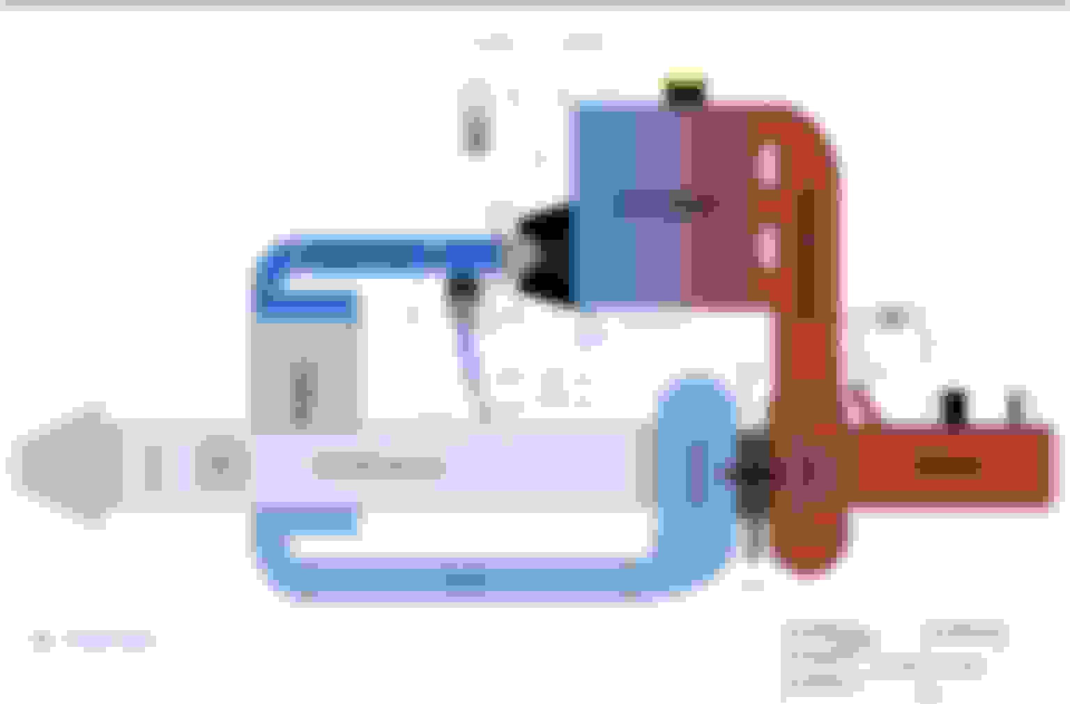


 Will it hold 13?