When you click on links to various merchants on this site and make a purchase, this can result in this site earning a commission. Affiliate programs and affiliations include, but are not limited to, the eBay Partner Network.
We’ll have to disagree on that. Under the proper conditions it can make mid-upper 500 whp on a 2-rotor engine; maxes out upper 7x - 80 lb/hr. However, with the 0.83 AR v-band inlet turbine it can’t make much more than 400 whp due to the exhaust flow restriction
I got the 100whp from your comment above.
As far as filling in Matchbot goes ...I have an actual engine with measured parameters to compare actual vs theoretical so have a pretty good handle on how the numbers fall into place .
... thinking thru the torque decline post peak,...on a turbo capable of blowing more air than I'm pushing thru it didn't make sense, and caused me to suspect it was EBC tuning vs. hardware related. ... reducing the EBC % LIMIT support my suspicion that it was indeed the LIMIT feature constraint having the unintended effect on torque...
It's been raining lately and I've some loose ends to sort..., but I'll continue retuning my EBC in this way... interested to see the... natural HP/torque curves of my 6266 with the LIMITING feature constraint fully lifted.
I still have some issues to sort, a boost leak being one, but w/ rain stopped and dry pavement... I did a 3rd gear pull today @ ~12 psi ensuring my EBC parameters were set to ensure that WARNING / LIMIT would not be engaged.
This should be a better approximation of the torque curve of my setup. Significant improvement: torque climbs smoothly until 6763 rpm. The implication of this result is encouraging...when applied to my previous 13 psi v-dyno in post #538:
.
Taking advantage of some Thanksgiving holiday time off to make progress on my winter 8 To Do list.
- Repaired leak and swapped back in my dual pass rad.
- Fashioned a bead crimping tool...$15.
- Inspected and reformed intake and charge sections, where required.
- Added beads, to supplement the welds, to problematic intake and charge sections
Note: Learned thinner stainless steel clamps are better than the wider t-bolt clamps which disperse clamping force over too great an area for this application.
Next up:
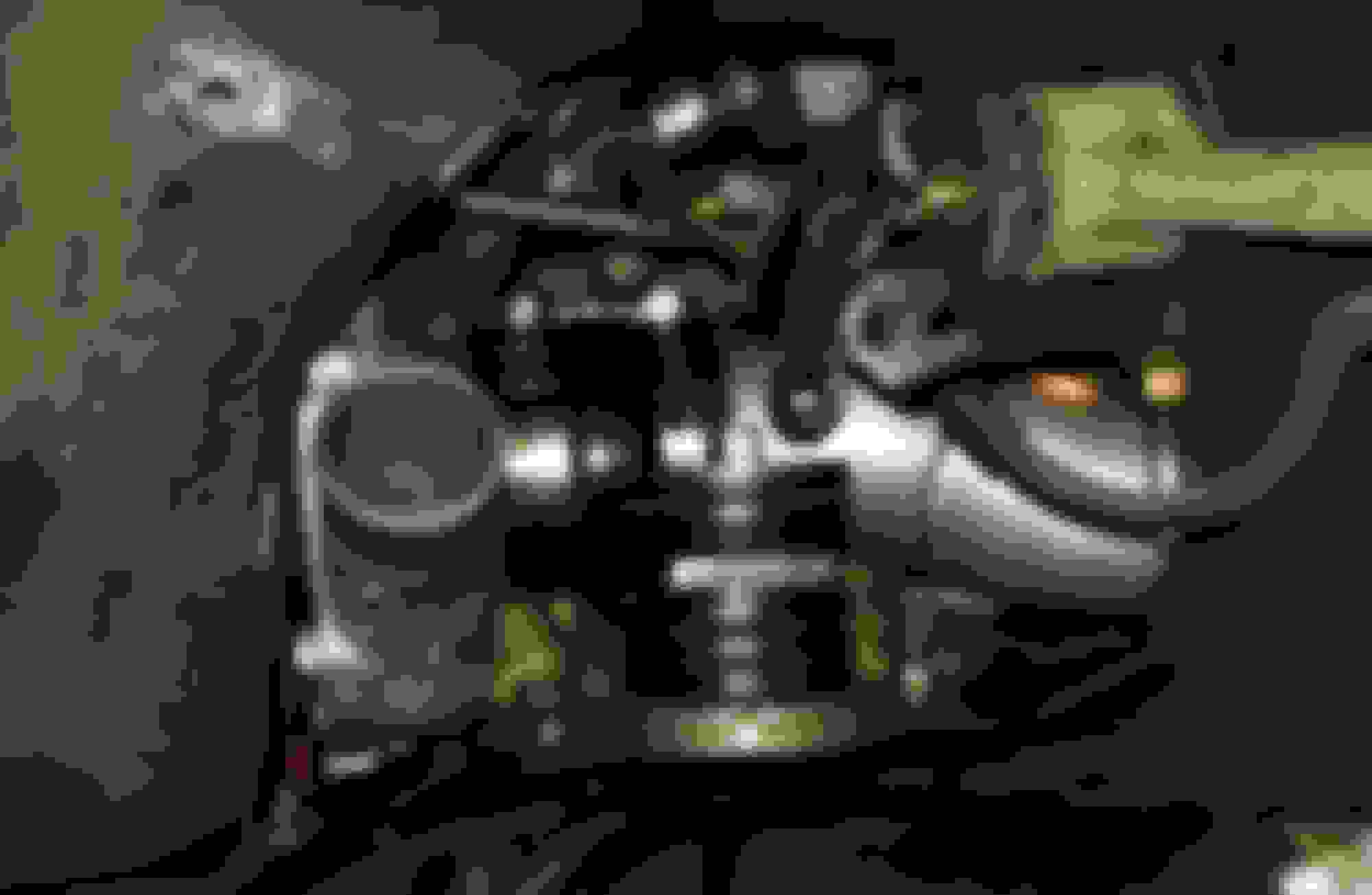
- install mini 8" tall IC.
- install charge & intake sections
- install new LRB aluminum under tray.
Bead crimping tool
. compressor inlet section w/ a knarly end and no welds or bead. (before) . Reworked compressor inlet section (after)
. Problematic throttle body charge section w/ new bead installed to augment the welds.
.
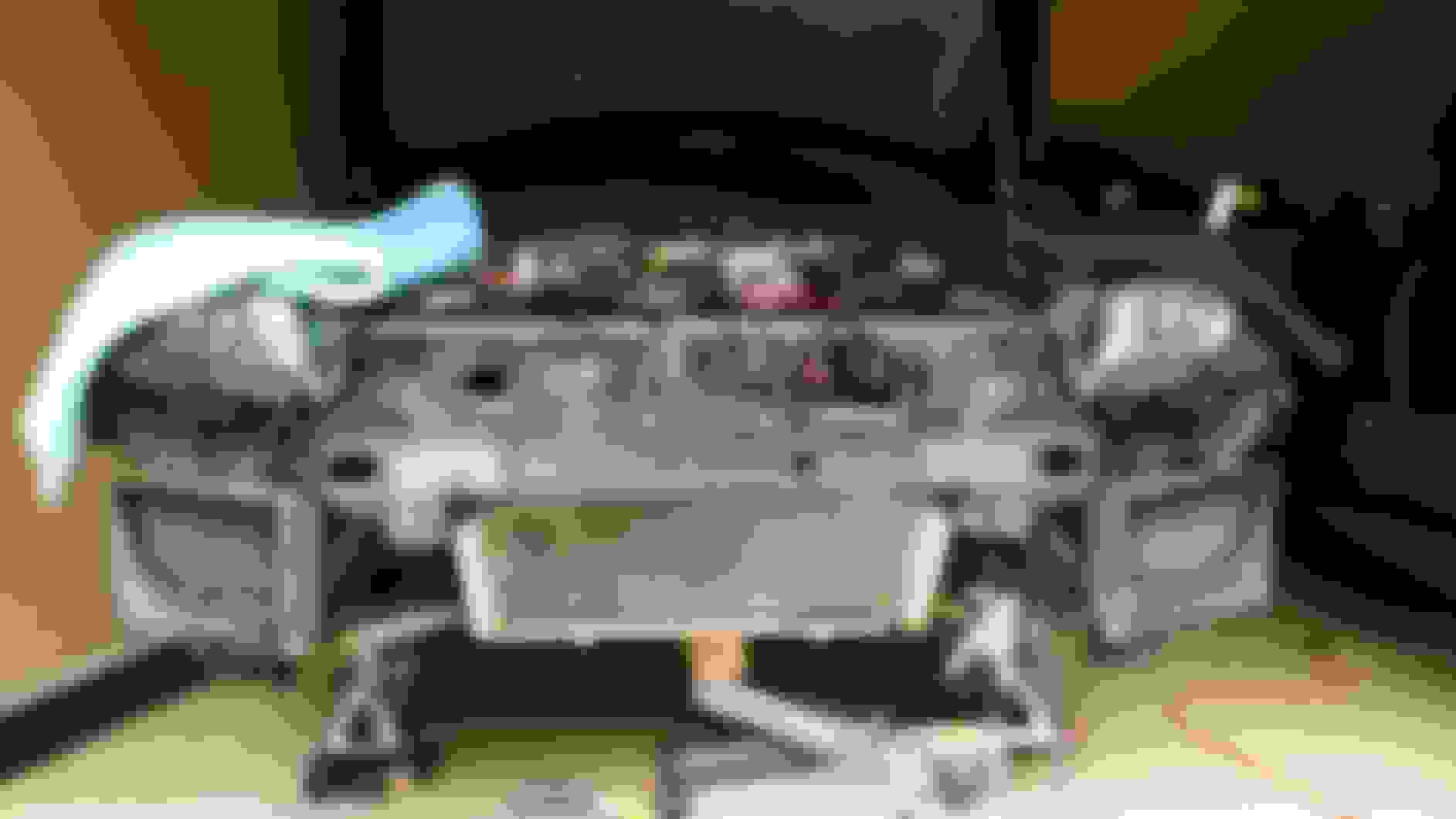
Dual pass radiator leaks repaired and reinstalled
. Mo'-tor mount rubbers swapped: 3 section rubber on the bottom, 2 section rubber on top.
.
looking good and will be much better control, now if you can get it back up to 260 ft/lbs and hold that across ...
Vdyno seems a bit fubar though. In the earlier 260 ft/lb peak graph it was showing 340hp/240ftlbs at 7500, here is still 240ftlbs at 7500 but 30 less HP. The same torque reading at the same rpm should produce the same HP reading.
Team, Thanks.
I'd been experiencing...
- a boost leak delaying spool (oddly intermittently)
- vacuum leak(s) causing leaner than desired afrs...during initial boost rise, then leveling nicely throughout the rest of the rpm range. The higher the boost...the more concerning
So, I'm hoping to optimize the system by ...among other things...better regulating afrs throughout the rpm range, and improving boost threshold and spool. If successful..., achieving previous boost levels won't be an issue.
Agreed...concerning the v-dynos. They are useful *approximations* of power levels, but generating them via M/E is definitely an art, not a science. And some are simply snippets of spirited driving rather than disciplined WOT pulls.
A little progress this evening after work...
- installed charge section from compressor outlet to my new mini IC.
- spent a good deal of time sorting out... and fabricating installation of the new mini IC.
The new IC looks so small compared to my old IC. Hoping it cools as effectively..
Next up:
- Install charge sections into engine bay, and to the throttle body
- Install LRB under tray
Note: Maxi IC m/b for sale once I confirm mini does the job.
. Mock up of mini IC, and comparison of mini vs. maxi IC
.
Glad I didn't toss the RX8Performance IC mount. Works well for the shorter IC.
.
Re-installed...
- CAI and MAF sections
- post IC into eng. bay, and to throttle body charge sections
- vac & charge lines ....(jet air, OMP, oil catch, BOV, charge signal line to WG)
- ECT and IAT sensor wires
Note: The fully rolled / beaded section ends gave confidence to install charge sections w/ only shorter couplers w/ no further reinforcement.
Next up:
- install the LRB aluminum under-tray.
- dbl check everything...
Bay (left)
. bay (front)
. bay (right)
. IC - bay, bay - throttle body charge sections, coupler, and new clamps
.
Quick fyi...for any installing the RX8Performance kit.... Beware...installing the front large under-brace may make contact w/ the ex-mani... ???
Originally Posted by TeamRX8
The issue is likely the RX8P engine mounts. ... The turbo heat likely sagged them some too. An oversize fender washer on top (2” - 2.5” dia) with 1/4” tall spacer or stacked washers added between the new top washer and engine bracket should raise the engine and give some clearance. You might consider building a heat shield for the one on the exhaust side too.
Originally Posted by Brettus
Are you sure the rubbers are the correct way around Curtis ? The thicker rubber is normally on the compression side , you have it on the rebound?
Also: that large diameter washer on top is doing nothing . It would be better between the lower rubber and the plate that goes to engine.
Edit:
Team & Brett were correct...after swapping the passenger motor mount larger rubber to the bottom w/ a large washer on top under the brace arm (see post 566 pic), I was able to reinstall the largest under brace w/ no clearance issues.
Plan to install some heat shielding around the motor mount as well. Edit: Added.
Large under brace installed
. Heat shielded motor mount
Yea sorry for not being clearer. The large washer has to go on top of the rubber under the metal arm to distribute the engine weight across the full rubber bushing diameter. Looks like you did a good job all around.
Yeah, I understood that..., but the large washer's ID is too small, ~0.5", and the mount stud diameter is 1.5". I just bought the largest new washer I could find with ID >~1.5".
Hoping not to have sagging issues down the road with the mount heat shielded.
Problematic throttle body charge section w/ new bead installed to augment the welds.
Just looking at this again ..... I think it will still be hard to seal . You should remove the welds and crimp all the way around. Then smooth the top of the crimped ridge as much as possible so that creates the seal . ATM you have gaps between the crimped parts where air can escape and you rely on the hoseclamp to seal it to the pipe on a section that doesn't line up properly.
If you are having a hard time keeping couplers from bursting, I have found that rubbing the aluminum with a thin layer of hylomar helps. Especially if you twist the coupler back and forth a few times on the pipe until the hylomar tacks up real dry.... Or you could do it the boring professional way
Just looking at this again ..... I think it will still be hard to seal . You should remove the welds and crimp all the way around. Then smooth the top of the crimped ridge as much as possible so that creates the seal . ATM you have gaps between the crimped parts where air can escape and you rely on the hoseclamp to seal it to the pipe on a section that doesn't line up properly.
You know... I thought about doing that very thing before creating the bead around the welds.
I'll rework it. Thanks.
If you are having a hard time keeping couplers from bursting, I have found that rubbing the aluminum with a thin layer of hylomar helps. Especially if you twist the coupler back and forth a few times on the pipe until the hylomar tacks up real dry.... Or you could do it the boring professional way
Hmm, interesting....
I've used a small amount of hair spray to install the couplers this time round. I'll try hylomar when I reassemble the charge section to throttle body coupler above. Thanks.
I've a previous commitment that's going to interrupt progress for a few days...but I'm working on installation of a legit aluminum under tray atm. This puppy w/b tight as a drum.
That will work, but if you just take out the cheap permanent and removable rivets from the OE plastic one, replace them with larger rivet-nuts, and then use large flanged-head screws it pretty much makes the thing bullet proof.
True. I did something similar until now..., but mine was the original under tray and a bit beat up.
Just looking at this again ..... I think it will still be hard to seal . You should remove the welds and crimp all the way around. Then smooth the top of the crimped ridge as much as possible so that creates the seal . ATM you have gaps between the crimped parts where air can escape and you rely on the hoseclamp to seal it to the pipe on a section that doesn't line up properly.
Yes, I believe this will seal much better...
Originally beaded only between welds
. Taped and fully beaded
. JB Weld applied
. ....
Well......me too. Lol. The JB weld specs indicate a tensile strength of ~4000 psi, and withstands ~500 F temps when cured. Additionally, the boost force in the section should force the coupler to wedge the JB weld between the coupler and bead on the aluminum section all around.
Otherwise....
- awaiting delivery of a 90 degree coupler to fit my new IC to exit charge section
- need to customize the aluminum under tray to accommodate my IC inlet and exit charge sections and seal it up
- reinstall the charge to throttle body section and assoc. signal and sensor lines
Ok, you have a 3” OD tube curving into a 3.125”/80mm OD TB connection. The reason you’re having problems is because you’re trying to use a straight silicone connector on a curving tube bend.
the solution is to instead use a silicone reducing elbow by cutting it down to fit where you need it:
Team - Thanks. That's a good idea. I did that very thing...i.e. install a 45* elbow on the other end of the same charge section at the FMIC --> eng bay -[coupler]- eng bay --> TB connection ...shown below.
But having fully beaded the section end...I'm going to try the straight coupler...first, and move to an elbow coupler if the connection still doesn't seal.
I've growing confidence that the fully beaded end will seal. To keep this post clean... I'll explain why below.
Originally Posted by jcbrx8
Installing ...charge sections:
,,,FMIC --> eng bay,
,,,eng bay --> TB
- discovered that the last charge section (pre-TB) is shorter than ideal. - Resolution...ordered 6” long, 45-degree coupler. Worked perfectly.
.
.
.
What Brett said below was a paradigm shift in my thinking regarding "how" to create reliable coupler seals.
Originally Posted by Brettus
Just looking at this again ..... I think it will still be hard to seal . You should remove the welds and crimp all the way around. Then smooth the top of the crimped ridge as much as possible so that creates the seal . ...
My kit came w/ small welds at 3, 6, 9, and 12 o'clock positions, which b/c they did not completely circumference the charge sections caused me to believe these were ONLY for the purpose of creating a mechanical "connection" to keep the section from blowing off under boost, and that the coupler clamping force created the airtight "seal". While this m/b a method of sealing couplers..., I don't believe it's the better method.
Brett's above comment caused me to consider generating the seal in the same way a cork seals, which relies on a gradually increasing O.D. In this case the more pressure applied..., the tighter the seal.
This is the dynamic I'm trying to create, and am optimistic will work. If it works on this difficult curved section...it w/b effective on ANY charge section...
.
 11-24-2019, 03:04 PM


") ... reducing the EBC % LIMIT support my suspicion that it was indeed the LIMIT feature constraint having the unintended effect on torque...
... reducing the EBC % LIMIT support my suspicion that it was indeed the LIMIT feature constraint having the unintended effect on torque...


 ???
???