2010 Turbo Build: a.k.a. "Project JETS3T 8"
 01-03-2011, 07:01 PM
#151

Dang, I've got an idea...completely remove the bulky center insert and weld maybe a 1/4" thick divider to the actual exhaust manifold so that it protrudes outward and into the center port, effectively acting as a divider, but a much leaner one. I think I might just try that, need to talk to Elliot about this.
Thx Brettus for bringing the center exhaust sleeve issue to light!
Thx Brettus for bringing the center exhaust sleeve issue to light!
 01-03-2011, 07:29 PM
#152
I still think four exhaust ports is the way to go, but the idea of welding the divider to the exhaust manifold is a great, but not new I believe, idea. Didn't we see that on an early NA header by somebody?
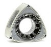
Hope you don't mind me nabbing your "removed sleeve" pic from your album.

edit: uploaded my center insert pic from renny #1 at 86K mileage all NA attached
Hope you don't mind me nabbing your "removed sleeve" pic from your album.
edit: uploaded my center insert pic from renny #1 at 86K mileage all NA attached
Last edited by Nemesis8; 01-03-2011 at 08:52 PM.
 01-03-2011, 07:43 PM
#155
Well - it has to help retain heat for spinning up the turbo and preventing too much heat from being picked up by the surrounding water .
If I was going to try something I think I'd leave the sleeve in and just remove the divider . Then weld material to the housing so as to create a radius that covers about 1/2 the port . I think the deflection of gases would be enough to prevent any damage to the opposite rotor .
If I was going to try something I think I'd leave the sleeve in and just remove the divider . Then weld material to the housing so as to create a radius that covers about 1/2 the port . I think the deflection of gases would be enough to prevent any damage to the opposite rotor .
01-03-2011, 09:34 PM
#156
Registered
Thread Starter

Well - it has to help retain heat for spinning up the turbo and preventing too much heat from being picked up by the surrounding water .
If I was going to try something I think I'd leave the sleeve in and just remove the divider . Then weld material to the housing so as to create a radius that covers about 1/2 the port . I think the deflection of gases would be enough to prevent any damage to the opposite rotor .
If I was going to try something I think I'd leave the sleeve in and just remove the divider . Then weld material to the housing so as to create a radius that covers about 1/2 the port . I think the deflection of gases would be enough to prevent any damage to the opposite rotor .
 (Keep in mind though, I wouldn't do this without adding additional countermeasures such as larger more efficient (or additional) radiator, high flow water pump, etc.)
4.2. Retaining Heat of the Exhaust Gas
In order to retain heat of the exhaust gas from the
combustion chamber to the catalyst, two measures were
taken: The exhaust port has a stainless thin-walled
insert (made of heat resisting stainless alloy) and the
exhaust manifold has two layers of air layer for heat
insulation and small volume thin-wall inner tube. This
allows for the retention of exhaust gas heat from
combustion chamber to the catalyst. Because of the
heat retention, gas temperature at a catalyst upstream
could increase about 140 degree C in the USA LA-4
mode drive, improving catalyst�s conversion capability.
Fig. 24 shows structure of the exhaust port insert and
exhaust manifold.
 01-03-2011, 10:07 PM
#158
Registered
Thread Starter
http://www.youtube.com/watch?v=uO1782B6RZw
01-04-2011, 12:29 AM
#159
Registered

Join Date: Feb 2007
Location: Canada
Posts: 27
Likes: 0
Received 0 Likes
on
0 Posts


 01-04-2011, 01:18 AM
#160
Registered
Thread Starter
01-05-2011, 12:06 PM
#161
Bat Mobile Driver

 01-05-2011, 07:35 PM
#163

No, that's not the point. It won't suddenly blow your engine, but blasting the side seal, corner seal, and rotor side is going to greatly shorten the effective engine life particularly on long duration WOT runs
Last edited by TeamRX8; 01-05-2011 at 07:40 PM.
01-07-2011, 12:26 AM
#170

do you really want more area/volume in the exhaust? enlarging the pipes will drop the velocity.
the side port area is larger than the peripheral exhaust port. it is the duration of the port that has been reduced. makes me think more duration is the key to more exhaust flow.
the side port area is larger than the peripheral exhaust port. it is the duration of the port that has been reduced. makes me think more duration is the key to more exhaust flow.
01-07-2011, 10:28 AM
#171
Registered
Thread Starter
do you really want more area/volume in the exhaust? enlarging the pipes will drop the velocity.
the side port area is larger than the peripheral exhaust port. it is the duration of the port that has been reduced. makes me think more duration is the key to more exhaust flow.
the side port area is larger than the peripheral exhaust port. it is the duration of the port that has been reduced. makes me think more duration is the key to more exhaust flow.
01-07-2011, 01:39 PM
#173
Registered
Thread Starter
This is a great photo too, I do like Fig. 24 because it actually shows the function of the inserts acting as a medium to transfer heat to the exhaust manifold. Fig. 9 does give you a better overall idea of the inserts in general though.
Thx Nemesis.
Thx Nemesis.
Last edited by JETS3T8; 01-07-2011 at 01:49 PM.
01-07-2011, 01:46 PM
#174

There is no way that that insert isn't designed to lessen heat transfer to the iron and hense the coolant. That small air gap allows more heat to be expelled into the exhaust and evens out the instantaneous pulse temps that the iron and the opposite rotor would see if it wasn't there.
I can't see how there will be a viable option with that removed completely...
I wish someone had data for the flow volumes through the 2 exhaust ports...I would thingk more goes to the outside ports,,,and much less through the center ports.
I can't see how there will be a viable option with that removed completely...
I wish someone had data for the flow volumes through the 2 exhaust ports...I would thingk more goes to the outside ports,,,and much less through the center ports.
01-07-2011, 02:17 PM
#175
Registered
Thread Starter
There is no way that that insert isn't designed to lessen heat transfer to the iron and hense the coolant. That small air gap allows more heat to be expelled into the exhaust and evens out the instantaneous pulse temps that the iron and the opposite rotor would see if it wasn't there.
I can't see how there will be a viable option with that removed completely...
I wish someone had data for the flow volumes through the 2 exhaust ports...I would think more goes to the outside ports,,,and much less through the center ports.
I can't see how there will be a viable option with that removed completely...
I wish someone had data for the flow volumes through the 2 exhaust ports...I would think more goes to the outside ports,,,and much less through the center ports.
The roles of the exhaust sleeves have definitely shifted since the days of the peripheral exhaust ports in the aluminum rotor housings. They definitely served as more of a thermal barrier to protect the aluminum and coolant temps but also served as a medium to transfer/retain heat for emissions. But now that the exhaust ports have been moved to the cast iron side housings, they serve more as a medium to retain and transfer the heat rather than to mainly protect the housings and coolant temps. It really does make a lot of sense. Plus they did include this concept in an official SAE paper. (Keep in mind though, I wouldn't do this without adding additional countermeasures such as larger more efficient (or additional) radiator, high flow water pump, etc.)
(Keep in mind though, I wouldn't do this without adding additional countermeasures such as larger more efficient (or additional) radiator, high flow water pump, etc.)Last edited by JETS3T8; 01-07-2011 at 02:22 PM.