Pettit Super Charger Owners
Registered
iTrader: (1)
the rx7 owners did this a lot, even dave from kdr now speedone from pensilvania would cap them off. it made oil flow a little bit more than having the vacuum lines connected, i did it on all my rx7s i owned, never had any issue, but havent found anything on rx8 owners doing this.
Registered
RIP Furai
iTrader: (3)
OtherSyde, that makes sense, I haven't gotten that far in the install, but assumed I'd route it to the MAF pipe.
Regarding the oil injectors, I'm assuming the diaphragm in there is operated with the vacuum (pressure) from the vacuum lines, so removing and capping them would make it more like it was always under high load and therefore inject more oil. I'm guessing here.
With the RX-8, the thing to do is just tune it and increase the OMP oiling rate. This is very common when tuning this car in general. Most people up the rate. I'd go this route as opposed to the vacuum capping for the more precise and measurable change.
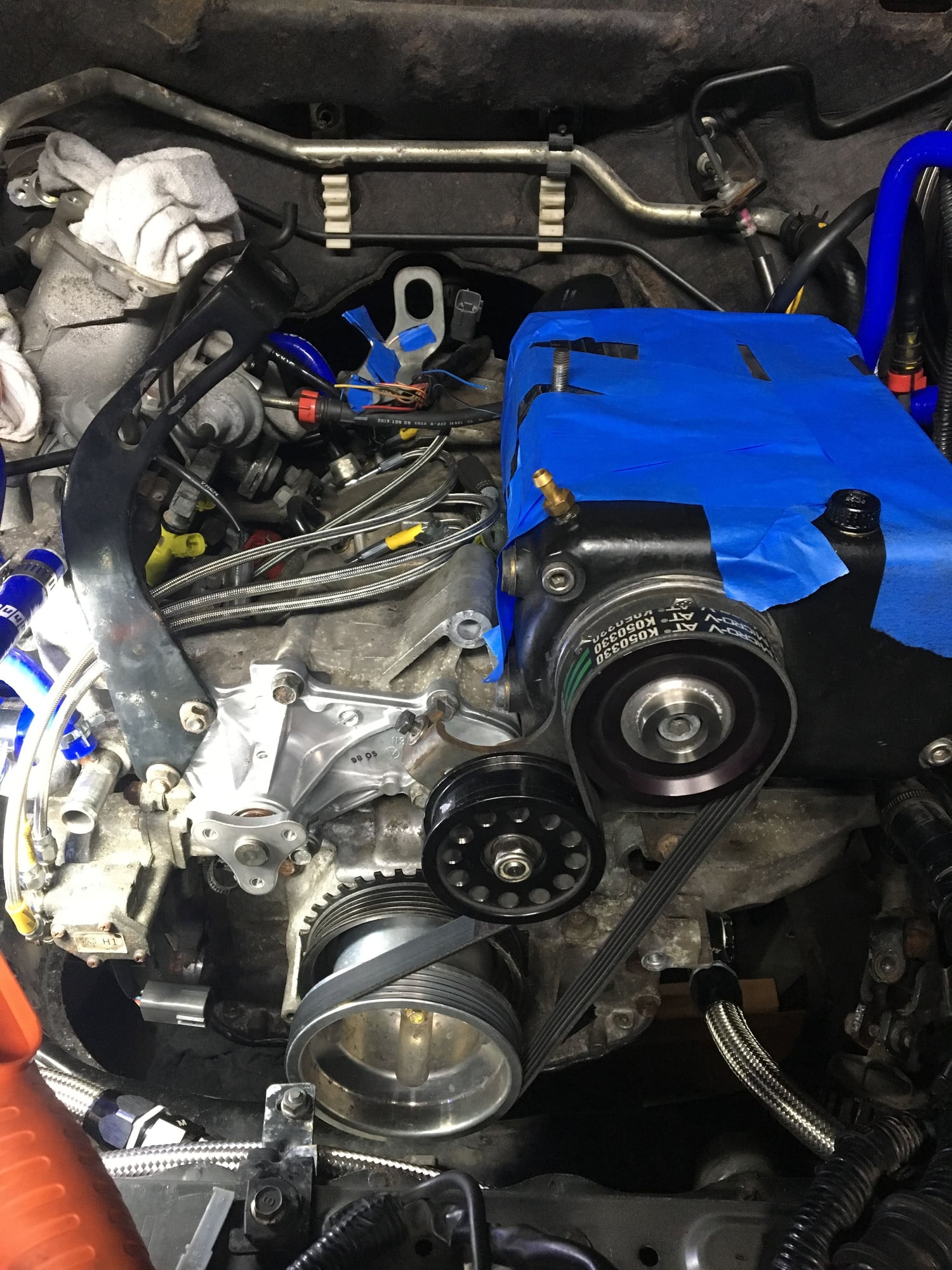
Wait, I was under the impression that you were supposed to run a vacuum hose from that nipple to where the brake booster vacuum hose went on the (big black disc-looking) brake booster chamber right in front of where the driver sits? There's nowhere else to hook this up to once you remove the plastic OEM UIM, and my kit came with a hose that looks exactly like this attached to that very nipple on the Pettit intake (right below where the "P" and "E" are on the side, see my pic above), and the hose is curved/bent/molded in such a way that it perfectly lines up with the brake-booster nipple with the one-way check-valve tube connects to - the tube which would otherwise feed into the stock OEM manifold on top..?
Registered
Yeah sure; where does the other end go? I assume one connects to the drivers side of the Pettit manifold, but where does the T'ed off line go to? Is this standard on Pettit installs, or an extra thing?
Registered
iTrader: (1)
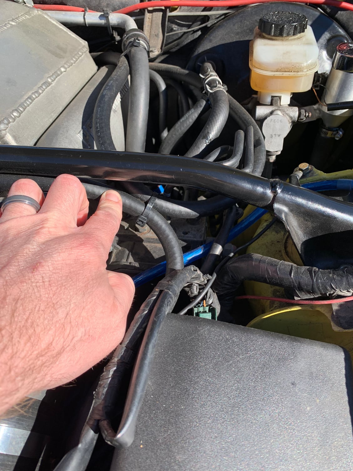
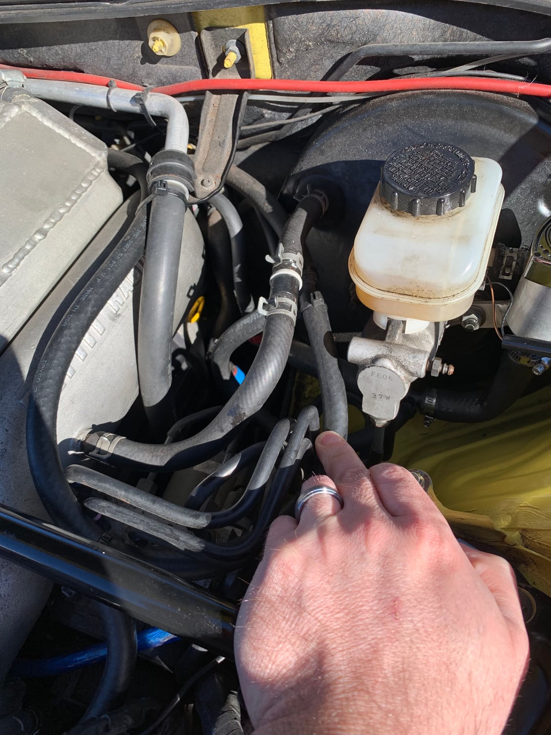
any supercharge owners that have detailed pics of the vacuum lines set up please post pics !!!!! it seems that everyone routs hoses different on there cars. thanks john
Registered
iTrader: (1)
Registered
iTrader: (1)
Registered
Keck - thanks for the pics thus far, and I could really use some "real world" instructions on where all these tubes actually go - the Pettit manual doesn't account for a lot of mods we've all made and it seems a bit unclear at times and very non-descriptive (I think they just sort of assume that we're already all experts who have the location and purpose of every coolant tube and vacuum hose memorized like it's common sense or something), and I'm almost sure they didn't list every single one in their diagrams, I feel like some are missing, like they just assumed we'd sort of figure it out since it's so basic or something.
Like for instance, the tee-off line halfway down the oil-filler extension hose - where does that go to? And the barb-connector at the front of the actual compressor (I think it points backwards), and also the other one at the rear that's directly forward and below the where the blow-off valve attaches (can be seen in my pic above comparing the size of the Pettit BOV to the new TiAL BOV)? And the connector on the underside of the Pettit UIM? It seems like there are multiple possible configurations for some things, and also the fact that the stock MAF housing has three vacuum-line connectors but the Pettit (and also the RX8Performance) MAF housing section only has two - where does the third line connect to now? It all seems a bit vague and dicey; if we could see and understand the running setup of someone's actual real-world, functioning configuration I think we could grasp it better.
Thanks for any pics and details!

Othersyde
In my one pic above, the vacuum line runs from the barb on the side of the compressor to the brake booster. The middle has a check valve.
I only have 2 hoses from my MAF. One runs to my oil catch can. The other is a short hose to the throttle body. There is no coolant running through our TB after setting up our kits. I am fairly certain mine runs the default vacuum route that I had posted earlier in this thread since the shop used that guide when they installed my reman motor. They never asked about running it a different way or reached out to Pettit that I am aware.
Last edited by keck03; 04-17-2019 at 03:20 PM.
Registered

Othersyde
In my one pic above, the vacuum line runs from the barb on the side of the compressor to the brake booster. The middle has a check valve.
I only have 2 hoses from my MAF. One runs to my oil catch can. The other is a short hose to the throttle body. There is no coolant running through our TB after setting up our kits. I am fairly certain mine runs the default vacuum route that I had posted earlier in this thread since the shop used that guide when they installed my reman motor. They never asked about running it a different way or reached out to Pettit that I am aware.
1. Oil catch cans usually have two hoses, right? An incoming and outgoing hose, right? The hose running from your MAF intake tube must be creating a suction, right? So it must be the catch-can's outgoing hose (outgoing from the catch-can to the MAF). Where does the incoming hose to the catch can come from? Where is it sucking the blow-by oil from (which is collected in the catch-can)?
2. I see up there on the left side of the diagram that there is the "Purge Valve" - is this the valve you remove from the stock plastic upper-intake manifold during installation and reuse? Or is this a reference to the BOV? I'd assumed the fatter red tube going to the Purge Valve from the compressor was coming from that smaller mysterious barbed nipple in front of where the BOV connects to, but is this actually the BOV and 1" BOV connection? And if so, what is the smaller barbed connector (next to/in front of to the 1" BOV connector) connected to? There should be two connectors at the rear-left of the compressor, but they only show one and that is really confusing :/
3. What are the "Fuel and Purge Pipe Connections" in the upper-right of the diagram? Is this a separate piece like the Purge Valve or is this something that is attached to the car or engine? Or is that the little thing you remove from the plastic OEM UIM during installation? They're so vague in their terminology...
Sorry for so many questions; the way they did their manual just feels a bit sparse and incomplete, leaves me feeling a bit apprehensive about the installation. Again, thanks for your insight and help here!
Modulated Moderator
iTrader: (3)
1.
Vent hose is basically bidirectional. Usually the system has positive pressure and will vent into the catch can... the catch can can either be re- routed into the intake like the diagram or can be vented to atmosphere. Just dont let it get plugged up by having it blocked off by the residue in the catch tank
2. The purge valve is off the stock OEM manifold. It connects between the vent line coming from the fuel tank area and connects to the manifold when the purge solenoid is open.
3. The purge vent line and the fuel line come up to the firewall area near where the clutch line. They are steel lines One has a red connector and the other blue
Registered
iTrader: (1)


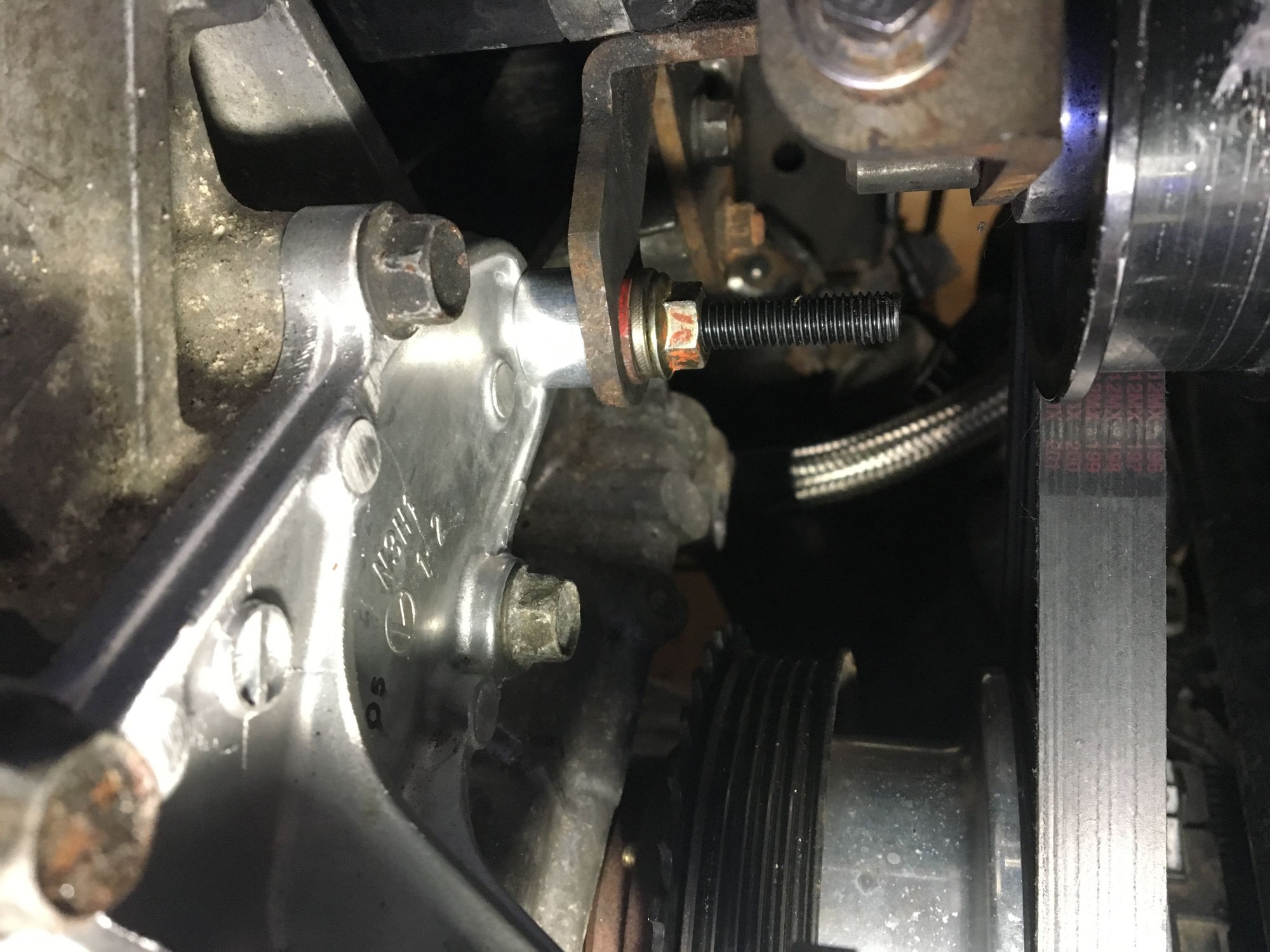
here some pics and videos with my questions. othersyde does you bolt extended as much as mine?? i had to put 1 washer and a lock washer on to fill in the gap!
Boosted Kiwi
iTrader: (2)
These lines seem to get messed up a lot . There is often more than one way to achieve the same result and so people get confused about which is right, which is best etc etc . IMO ...people should try to understand how stuff works , what is important/what isn't rather blindly follow what people tell them .
/Rant
/Rant
Registered
Jorx - Yes, my mounting stud is super-long too, WTF! The manual very specifically states that it is a 150mm M8 stud and IIRC it even mentions that specific stud on the compressor installation page, and there is nowhere else you would possibly use it anyway! I dunno, it looks like it actually maybe needs more of a 125-130mm stud? I will probably cut one of mine down (I got a 2-pack) by about 20mm and see if that works out better.
Also I was wondering, how many miles are on your engine? Or are you installing your SC on a newly-rebuilt/upgraded engine like me? FYI this was not by choice lol, I lost coolant on the SoCal freeway and fried an internal coolant seal at 61K last year. About 1,100 miles on the new Rotary Resurrection engine.
As for the tubes, lord only knows. I've been super busy lately with no chance to start my install, but I want to ASAP and I may get a chance in the next 2-4 weeks to do it. Then we can struggle in confused futility together!
Last edited by OtherSyde; 04-20-2019 at 08:25 PM.
Registered
iTrader: (1)
othersyde my motor has 75K on it. bought it 5 years ago with 64K and premixed it since!!! no issues with the motor.
Jorx - Yes, my mounting stud is super-long too, WTF! The manual very specifically states that it is a 150mm M8 stud and IIRC it even mentions that specific stud on the compressor installation page, and there is nowhere else you would possibly use it anyway! I dunno, it looks like it actually maybe needs more of a 125-130mm stud? I will probably cut one of mine down (I got a 2-pack) by about 20mm and see if that works out better.
Also I was wondering, how many miles are on your engine? Or are you installing your SC on a newly-rebuilt/upgraded engine like me? FYI this was not by choice lol, I lost coolant on the SoCal freeway and fried an internal coolant seal at 61K last year. About 1,100 miles on the new Rotary Resurrection engine.
As for the tubes, lord only knows. I've been super busy lately with no chance to start my install, but I want to ASAP and I may get a chance in the next 2-4 weeks to do it. Then we can struggle in confused futility together!
Also I was wondering, how many miles are on your engine? Or are you installing your SC on a newly-rebuilt/upgraded engine like me? FYI this was not by choice lol, I lost coolant on the SoCal freeway and fried an internal coolant seal at 61K last year. About 1,100 miles on the new Rotary Resurrection engine.
As for the tubes, lord only knows. I've been super busy lately with no chance to start my install, but I want to ASAP and I may get a chance in the next 2-4 weeks to do it. Then we can struggle in confused futility together!
Registered
Wow, putting boost on a 75,000+ Renny! Ballsy, man. 5-8psi of SC boost is known to be pretty gentle on our engines though, so hopefully your engine lives 100K and beyond!
Registered
Also, I remember that the extended spark-plug wire lengths need to be 22" and 27", but did you ever happen to figure out the coil extension length needed? I want to order from BHR soon so I can be ready to install when the time presents itself!
Last edited by OtherSyde; 04-23-2019 at 04:38 PM.
Registered
iTrader: (1)
my boy is doing it for mebut i will take pics and videoof it!!
Hey I saw some pics of your car on another image web site called imgrumweb.com (at least it looks exactly like yours) showing you're doing some harness rewiring? If you have the time, would you willing to document/take pics of what wires you moved to where? The Pettit manual is a bit vague but I think I basically get it, but their pictures are absolute pixellated blurry garbage lol, I think they used a mid-2000's flip-phone or maybe a potato to take their pictures. Your install looks so clean and fresh and your pics are so crisp, it would be really easy to see clearly where everything goes!
Also, I remember that the extended spark-plug wire lengths need to be 22" and 27", but did you ever happen to figure out the coil extension length needed? I want to order from BHR soon so I can be ready to install when the time presents itself!
Also, I remember that the extended spark-plug wire lengths need to be 22" and 27", but did you ever happen to figure out the coil extension length needed? I want to order from BHR soon so I can be ready to install when the time presents itself!


