When you click on links to various merchants on this site and make a purchase, this can result in this site earning a commission. Affiliate programs and affiliations include, but are not limited to, the eBay Partner Network.
Hey I saw some pics of your car on another image web site called imgrumweb.com (at least it looks exactly like yours) showing you're doing some harness rewiring? If you have the time, would you willing to document/take pics of what wires you moved to where? The Pettit manual is a bit vague but I think I basically get it, but their pictures are absolute pixellated blurry garbage lol, I think they used a mid-2000's flip-phone or maybe a potato to take their pictures. Your install looks so clean and fresh and your pics are so crisp, it would be really easy to see clearly where everything goes!
Also, I remember that the extended spark-plug wire lengths need to be 22" and 27", but did you ever happen to figure out the coil extension length needed? I want to order from BHR soon so I can be ready to install when the time presents itself!
OtherSyde,
I'll try to get you some pictures, but I already have the harness rerouted and all taped up. I just need to add the split loom over it. Bit I rerouted the MAF wires and coil pack wires per the Pettit instructions (I'll add some "best practices" when I get some pics). I only had to cut 1 wire, and it was a ground wire off of a ring terminal that will get a new crimp on terminal and be grounded elsewhere. No wires were cut say right in the middle where they would need to be spliced back together. I did this to save about $100 (this project is getting expensive) and not have BHR make the extended harness (though that would have looked nice I'm sure). I figured I was already at it, so I might as well do the coil wires too. Also, I bought 30" spark plug wires and I'll cut and terminate myself. The longest I measured that I would need was 28", and that had some slack in it, but I got 30" to be safe. I haven't installed this stuff yet so can't confirm I'm 100% good just yet. Also, FWIW, I'm installing the coils on the LRB Speed air box tray, so I'm not sure the position is exactly as Pettit intended, but it's in the same area.
I see I missed a bit about the hose routing too... I agree it's a bit lacking in explanation, but I've tried to become an expert in the vacuum system, etc. so I can make sense of it myself, as Brettus mentioned. Honestly, with mods this significant, I think that I should really understand what's going on with the setup - there really aren't many (or any) others with this/my exact setup that could help anyway.
I believe I know how I want to route everything, but until I do and give it a try, I don't want to share it here in case I'm wrong, so that way I won't confuse everyone.
Alright OtherSyde (and others) who asked, here's my attempt to help with the rewiring required. Let me first say that not all harnesses are the same, so yours may or may not require the exact same steps. And if you mess something up, don't blame me!
Also, I did this at 2 different times. I was originally only doing the MAF plug and going to buy an extended coil harness, but then later changed my mind for financial reasons. So if you see the MAF wire done in some pictures of the process, that's why.
Okay, on to the directions!
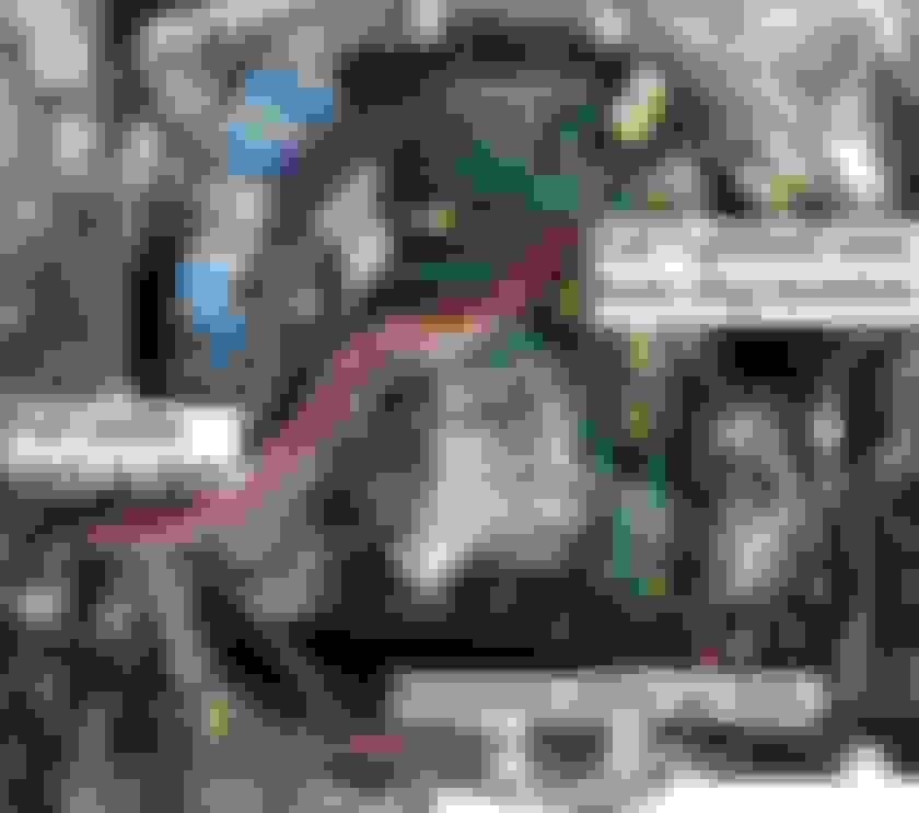
I've labeled the images 1-4. In all of them, if you see a red line, that was tape/split loom/wire wrap that I removed for this process. Green lines indicate tape/loom I didn't need to remove. Purple is the new rerouted wires. You basically need to fully unwrap the MAF and coil wires back to the main "trunk" in the harness, then unwrap that main trunk back to the ECU (or to where the wires will now split from the main trunk, but that's close enough to the ECU that I'm just going to re-tape it all).
So, start by unwrapping all the wires marked in red. It's at this point you'll be mesmerized by all the pretty colors of the 100 wires you'll see, and regret will set in instantly. But you're in it this far, so keep going!
You will then need to de-pin the MAF harness as the Pettit manual says. I used a tiny flathead screwdriver (like used for glasses or jewelry) and with some patience, got all 6 pins out without damage. Make sure you note the order of the wires. If it's the same as mine, this image can be your reference.
You DO NOT need to do this for the 4 coil plugs (even though the manual says you do), but make sure you have them marked as to which plug goes where. Here is where you will need to cut the one ground wire I mentioned in my last post. There is a rubber connector that takes the 4 coil plug ground wires (black) and reduces them to one ground wire. Once this is untaped, you can trace the one ground wire from here to a ring terminal (flat round metal washer) that is bolted to the top of the engine. This ring terminal has 3 ground wires going to it on my car. Cut the coil ground wire off of it. You'll need to put a crimp on ring terminal on the end of the wire you just cut and ground it elsewhere after the rewiring is complete. Sorry, I didn't have pictures of this, but it's self-explanatory once you get in there and I think the Pettit manual covers this process.
Now you'll need to pull the 6 MAF wires back through the main trunk of the harness to the spot indicated in the manual (where a big black plastic clip holds the harness in). You can then reinstall them into the plastic plug you took them out of, making sure you have the 6 positions correct. You'll then need to do the same for the 4 coil plugs and resonance eliminator (or whatever the hell that's called). See image 4. I was able to do this without de-pinning the coil connectors without knotting up the wires, but if you can't do that, you might want to de-pin the 4 coil plugs too. It's not hard, just tedious.
You can then tape/loom/cover the wires back up however you see fit. As you can see, the purple rerouted lines will reach the new coil and MAF locations, no problem.
That's it! Hopefully that helped. If you have questions, let me know.
If I ever get this project finished, I can try to do something similar with the vacuum lines if you all haven't sorted that out by then.
In my one pic above, the vacuum line runs from the barb on the side of the compressor to the brake booster. The middle has a check valve.
I only have 2 hoses from my MAF. One runs to my oil catch can. The other is a short hose to the throttle body. There is no coolant running through our TB after setting up our kits. I am fairly certain mine runs the default vacuum route that I had posted earlier in this thread since the shop used that guide when they installed my reman motor. They never asked about running it a different way or reached out to Pettit that I am aware.
Sorry for the long delay. In my current running setup the hose which originally ran from the T to the MAF is essentially cut in half with it going to a oil catch can. Line in runs from the T and line out runs to the right side of the MAF. I have run the catch can for around 4-5k miles and really have not "caught" any significant amount of oil.
Thanks for the wiring update Oblit, that helps to explain it and lets me sort of visualize the final product a lot better!
And Keck, for now I think I won't run an oil catch-can just yet, but maybe in the future if you're not catching a lot, but thanks for the explanation as well!
No problem. I have the clear tube on the side of the catch can and do not see any. I was going to open up the catch can and just verify it in the next couple of weeks.
did any of you guys upgrade your fuel pump ??? or leave the oem for the 8psi of boost? my car is 2007 so all the bugs were fixed by the time my year came out.
did any of you guys upgrade your fuel pump ??? or leave the oem for the 8psi of boost? my car is 2007 so all the bugs were fixed by the time my year came out.
I bought a DW200 pump. I haven't installed it yet though.
did any of you guys upgrade your fuel pump ??? or leave the oem for the 8psi of boost? my car is 2007 so all the bugs were fixed by the time my year came out.
Mine is 2007 as well; I'm leaving the stock fuel pump for 8psi, since everything I've read suggests that it is plenty sufficient for such low boost. You really only need the upgraded fuel pump and injectors if you're bumping up to 11psi, or that ridiculous 13psi pulley (which I think gives your like 350+ whp or something but also ruins your engine after 15-20k miles lol)
You should do an S2 fuel pump conversion for no other reason that it’s an inherently better design with replaceable components like fuel filter, pressure regulator, etc. It also has a higher flow capacity; I have the test results posted in the S2 forum area, and resolves most of the low fuel level starvation issues the S1 is well known for.
In addition to just being a poor overall design, the biggest issue with the S1 housing is that the main fuel filter isn’t replaceable. The only way to fix that is to replace the entire fuel pump module assembly which most owners are a bit derelict on maintaining; as long as it’s still running then it must be ok = fail. Putting an increased capacity pump in it is only going to limp you along so far before all the other limitations will eventually cripple it.
Personally I wouldn’t put a bigger pump in one either. For FI my recommendation would be to instead use an electronic fuel pump modulator tied into the boost signal.
I've looked into the S2 pump and agree it's a better solution. The only reason I didn't move forward here is the fuel level sensors. The way I understand it, there is one in both sides of the tank and replacing just the driver side one with an S2 unit causes the fuel gauge to read incorrectly. You can then replace both sensors but you're doing some wire cutting and splicing which I wasn't a fan of, and I'm not sure that even fixed the issue. Plus, I think you have to do some hose cutting to get the S2 pump housing in as the fuel line is a different size.
Is all of that correct? It's there a more plug and play solution? If so I'd buy an S2 housing and use that. Thoughts?
No, the pump has nothing to do with the sensors other than having the correct wiring connector for the S1 float where it plugs into the electrical pass-thru connection in the S2 pump module top. You just buy the S2 float and swap the connector; no cutting, soldering, wiring req’d.
You do have to change the quik-disconnect connector for the siphon hose coming from the RH saddle side where it attaches to the pump module. But come on man, look at all the mods you guys are making for this SC setup. I had to chuckle a bit ...
I hear you on the mods required here, but I've actually bought all duplicate parts for anything that gets cut so really I can 100% revert to stock if I ever felt the need. It's probably all a waste of money, but I just felt that's how I needed to go about it.
does it matter how the injector clips are plugged back in??? i think there pluged onto the right injectors. wire harness was away at my boys for redoing the harness. i forgot what clips go to what injector. well ill find out soon i guess
does it matter how the injector clips are plugged back in??? i think there pluged onto the right injectors. wire harness was away at my boys for redoing the harness. i forgot what clips go to what injector. well ill find out soon i guess
Yes this is very important. The rotors are 180 degrees offset and the primary/secondary/tertiary injectors don't fire the same. You'll need to be sure which goes where.
Alright! So I was on the freeway on my way home yesterday and some little black Focus ST started revving and fluttering his turbo next to me. I'm too old to be street racing so I didn't waste time taking the bait, but it did make me go Alright, this getting goddamn ridiculous; I've gotta get this SC installation underway. I'm plenty aware that RX8's aren't meant to be off-the-line fast cars, but being left in the dust by what appeared to be a stock Focus ST (with 252HP at the crank and supposedly only 202-214HP at the wheels) is just straight-up demeaning. Time to stop procrastinating.
This motivated me to continue home and, since I didn't have anything else going on after about 5pm, I started tearing my engine bay apart, determined to get the undertray and rewiring done at least.
.
.
First, the easier project - swap out my shitty mangled stock undertray for the upgraded Pettit undertray with the SC coolers and induction hoods built in.
.
. A peek into the induction hoods at the coolers. The areas of the undertray beneath the coolers are cut out, so the air travels into the hoods and then and down/out. Smart design by Pettit - although I think this was a one-off by them, I believe you can get a very sweet aluminum setup by RX8Performance here: ACS Twin-Fan Cooling Setup
.
.
. Good lord, look how mangled my old undertray was! And all the blue overspray! I got the new one all installed though with no hiccups, it was pretty straightforward.
.
.
. And now, moving onto the bigger challenge - de-looming and rerouting this spaghetti-pile of wires :/
. Throttle-body wiring de-loomed all the way back to the big plastic clip right outside of the ECU box. I only had to de-pin the middle wire (green with yellow stripe) to do this; the rest freely de-loomed together as one, and weren't tangled separately into the main cluster of wires.
.
. And now you can see the coil wire and the throttle-body wires in their new light-blue wire loom, shucked all the way back to the black clip. I did not move the grounding points (the black 4-into-1 wires) for the coils yet because I haven't moved the coils themselves yet; they will be very easy to move and re-ground once I start the main install, but essentially all the hard work as far as wiring is done at this point.
.
Several small notes here: I only de-pinned the black and black/white-stripe wires (grounds I believe?) from the coil plugs - I left the colored signal wires attached and individually threaded the plugs/colored wires back through the main harness, to prevent any possible change or damage to the signal wires which are known to be a bit more sensitive to any changes. This was also done because as I pressed the pin-release tabs in each coil plug (using a tiny jeweler's screwdriver) and pulled the pins out, little bits of plastic would fly out too, and upon closer examination I quickly realized that these bits of plastic were in fact the 14-year-old, decrepit, heat-fried plastic pin-release tabs themselves - and as I suspected, when I put the pins back in, there was nothing left to hold them in their pin slots aside from a snug fit. My solution was to leave the colored wires unmolested and snug in their respective coil-plugs, and then once I'd re-installed the black and black/white pins after de-looming everything, I tightly anchored the ground wires in place by securing them via electrical tape to the snug colored wires which would not come out, and served to hold them in place. So a bit of improvisation there, but everything started up and seems to be working well.
It took me a good 5 hours but my harness is all de-loomed, re-routed, taped up, re-loomed, and ready for coil relocation! Now I just need 2 things: extended spark plug wires from Charles at BHR, and a supercharger base-tune! And also a window of time where I can take a few days of leave from work of course.
Sorry for the filthy engine bay - I didn't realize how dirty it had gotten! I'll polish it all up once I've got everything all pulled apart for the compressor installation
One question - IIRC, the lengths for the longer spark plus wires are 22" and 27", right?
Last edited by OtherSyde; May 19, 2019 at 06:21 PM.
That's good progress! Looks like you're getting things tidied up.
I think those measurements are right, but I just bought 30" wires from BHR with one end unterminated so I can cut to the exact length I want. I think a little extra slack might be good to make sure I can route them without worrying about them rubbing on a pulley or belt or sharp metal edge anywhere.
No, the pump has nothing to do with the sensors other than having the correct wiring connector for the S1 float where it plugs into the electrical pass-thru connection in the S2 pump module top. You just buy the S2 float and swap the connector; no cutting, soldering, wiring req�d.
You do have to change the quik-disconnect connector for the siphon hose coming from the RH saddle side where it attaches to the pump module. But come on man, look at all the mods you guys are making for this SC setup. I had to chuckle a bit ...
.
I agree with TeamRX8, go for the S2 fuel pump. the slight mods needed are no big deal, but the S2 pump is a world better than the S1. The S2 fuel pump swap thread here gives step by step directions for the swap. I did mine almost 2 years ago , it was no problem and what a difference. Cheers
You can buy and swap put those old ignition wiring harness connectors easily. They’re common and sold all over the internet.
Ah, good, I'll look for some. Probably not too expensive.
Also, my extended spark-plug wires are on the way from Charles at BHR, and I just ordered another 5' length of 5/8 blue silicone tubing for the SC coolant lines that will be visible in the engine bay because I just realized today that I measured wrong - I measured the tubing lengths back when I was still planning to use the plastic stock Pettit coolant reservoir which mounts further back by the battery, but now I have the BennettBuilt aluminum coolant reservoirs that mount way up in the front next to the engine coolant reservoir - thus requiring like 6-10" more tube length to reach. Oh well, it's fairly cheap and with Amazon Prime it'll be here in 2 days. Finally, I was able to log into MazdaManiac's web site and download his Supercharger Base Tune, so at least I will be able to start my engine after the install, even if it will need further tailoring for the tune to reach its potential. All in all it's starting to come together, and soon I will have little excuse left not to get this installation underway
[EDIT] - Just thought of two more questions that have been bugging me while staring at various installs and the Pettit manual:
1. The tube that normally connects to the top of the stock black plastic oil-filler neck nipple right below the oil cap (points forward) - where does this tube end up getting reconnected once the stock oil-filler is gone?
2. In the PDF manual on page 21, in the upper right of the "Hose Routing" diagram which has been posted several times recently in this thread, it mentions the "FUEL AND PURGE PIPE CONNECTIONS" denoted as a little dark-grey oval with two connectors, and there is one red "PURGE HOSE" going to one of the two connectors; where is this located in the actual engine bay? What am I looking for? And what connects to the other connector on this unit (nothing is connected in the Pettit diagram)? See pic below, in red text and purple text...
Last edited by OtherSyde; May 22, 2019 at 12:45 AM.
[EDIT] - Just thought of two more questions that have been bugging me while staring at various installs and the Pettit manual:
1. The tube that normally connects to the top of the stock black plastic oil-filler neck nipple right below the oil cap (points forward) - where does this tube end up getting reconnected once the stock oil-filler is gone?
2. In the PDF manual on page 21, in the upper right of the "Hose Routing" diagram which has been posted several times recently in this thread, it mentions the "FUEL AND PURGE PIPE CONNECTIONS" denoted as a little dark-grey oval with two connectors, and there is one red "PURGE HOSE" going to one of the two connectors; where is this located in the actual engine bay? What am I looking for? And what connects to the other connector on this unit (nothing is connected in the Pettit diagram)? See pic below, in red text and purple text...
Ah, so it's just represented as being unplugged/absent in the diagram because it doesn't apply directly to the supercharger or get messed with during the install, but it's actually already present and plugged in where it should be, and doesn't have to be modified?
Could someone snap a quick pic of where these two plugs (the ones marked as "FUEL AND PURGE PIPE") are in the engine bay? Or maybe just use MS Paint to mark them in one of the numerous pictures we've all posted of our engine bays so far? I don't know what they look like IRL and I just wanna be as prepared as possible when I finally start my actual install so I'm not fumbling around wasting time like a clueless idiot when the time comes... Thanks!