When you click on links to various merchants on this site and make a purchase, this can result in this site earning a commission. Affiliate programs and affiliations include, but are not limited to, the eBay Partner Network.
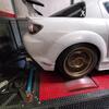
The two lines are the fuel supply and "return" (purge/vent) lines. They are on the driver side of the engine bay where the transmission tunnel meets the firewall. They originally had black lines that clipped on, one with a red band and one with a blue band I believe. I'm going on memory right now but I think there's a little 3 barb solenoid thing that was on the plastic upper intake section that you remove and one line goes to the purge line I mentioned above.
The line on the oil intake tube that you cut off was a vent tube. That's now achieved with the T connector in the 5/8" line that goes down to 3/8". That then runs to the intake to achieve the same vent.
The two lines are the fuel supply and "return" (purge/vent) lines. They are on the driver side of the engine bay where the transmission tunnel meets the firewall. They originally had black lines that clipped on, one with a red band and one with a blue band I believe. I'm going on memory right now but I think there's a little 3 barb solenoid thing that was on the plastic upper intake section that you remove and one line goes to the purge line I mentioned above.
OK I think I've got it - leave the blue one alone since it actually supplies fuel to the engine, while the red-clip one ends up going directly to the little 3-bard solenoid thing because it no longer has the black plastic stock upper intake to connect to, correct? Or do I have this backwards? [EDIT] - damn, looks like I might have this backwards since it looks like the intake-manifold vent/purge hose is blue-to-blue, like this here? And in this other pic from somewhere on this forum shows the underside of the stock UIM having the blue plastic clip attached? I mean it makes more sense that "red" would mean "flammable fuel". But then again, on a Mazda CX-7 at least, this guy in this video at 0:27 below says that the fuel line on Mazdas use a blue clip like I originally thought? ****, I keep finding conflicting information... Which is it?
Also Oblit on a side-note, did you find a solution to the varying tube sizes when trying to connect them directly to the little 3-barb solenoid? I remember you posted about this a few pages back...
.
.
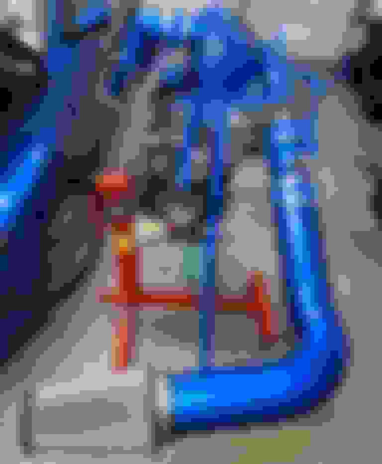
. EDIT - Adding this second CORRECT image below so any future searchers won't accidentally think the above image is correct and route their vent hose into their fuel line or something. To reiterate, the RED is the FUEL SUPPLY line, and the BLUE is the VENT/PURGE line to which you route your supercharger vent/purge-hose from the purge solenoid valve that you pull out of the underside of the plastic OEM intake manifold.
.
.
Last edited by OtherSyde; Jun 10, 2019 at 10:03 PM.
Decided to start putting together my tubing situation and figuring out where all the random bits that came with this go. . . . Not too difficult, judging by the tube sizes and configurations. I'm swapping out the pieces that will be visible with newer silicone counterparts. . . . And here we go! Tubing to BOV/UIM/Vacuum Chamber installed! . . . This piece was pretty self-explanatory too, based on the shape of it. . . . With this one I only bothered to replace the sections that will be visible. . . . Masked off, primered, painted, and clear-coated my MAF housing tube! . . . While I was busy painting, the mail came! My MAF-housing L-bungs (FYI I'm using
and they fit/screw into the MAF holes perfectly!) and permatex to seal them, as well as the double-ended 3/8" hose connector for bypassing the throttle body in the coolant loop! . . .
And here's the completed MAF-housing with the two bungs sealed in, ready for installation! . . .
And as a final bonus, I got my custom 23" and 28" (I had an extra inch added to each just to be sure) MSD extended Kevlar-jacketed spark-plug wires as well. Look how long they are next to the standard NGK wires! Reaching the relocated coils should not be a problem. . . Well, sadly that will probably be the end of my progress for a week or two at least due to work schedule, but I'll post another update once I make any more progress or source any more parts! Peace guys!
Last edited by OtherSyde; May 27, 2019 at 10:35 PM.
where are these hoses connected??? in black circle
The bottom/smaller one is a vent-hose that snakes back around the rear of the supercharger and plugs into the T-connection on the oil-filler tube on the drivers side along with the other vent-hose routed from the drivers-side of the MAF-tube. You can see it on the plumbing diagram in the Pettit manual, it's a light-blue 3/8" tube.
The top/bigger one is part of the coolant circulation loop and connects to the back top corner of the supercharger's inline intercooler and runs to the return inlet on your plastic coolant reservoir (connects to the higher-up inlet/nipple on the coolant tank which faces the rear of the engine; the lower nipple that faces forward is where your coolant pump connects to in order to draw coolant out and pump it down into the front-mounted Hayden mini-intercoolers that get installed in front of the radiator).
Last edited by OtherSyde; May 28, 2019 at 11:35 AM.
I haven't gotten around to getting hoses on yet, but I was hoping I could take a hose of the smaller diameter, hook it to the metal return line, and stretch the other end over the purge valve. If that won't work, I'll have to get a reducer adapter. I'm not sure that's much help, but didn't want to leave you hanging.
Also, looking good! I wish I had a spare engine to mock everything up on. That would be much easier than bending over the bumper or fender the whole time!
The bottom/smaller one is a vent-hose that snakes back around the rear of the supercharger and plugs into the T-connection on the oil-filler tube on the drivers side along with the other vent-hose routed from the drivers-side of the MAF-tube. You can see it on the plumbing diagram in the Pettit manual, it's a light-blue 3/8" tube.
The top/bigger one is part of the coolant circulation loop and connects to the back top corner of the supercharger's inline intercooler and runs to the return inlet on your plastic coolant reservoir (connects to the higher-up inlet/nipple on the coolant tank which faces the rear of the engine; the lower nipple that faces forward is where your coolant pump connects to in order to draw coolant out and pump it down into the front-mounted Hayden mini-intercoolers that get installed in front of the radiator).
The dual 5/8" to single 3/8" T fitting (which branches off from the green oil filler hose to the blue vent hose in the diagram above) came with my system so I didn't have to find it, but the closest thing I could find would be to buy this 3-way 5/8" T fittingand then slightly reduce the size to 3/8 using this 5/8" to 3/8" reducer for the vent hose.
As for pictures, I don't have my SC installed yet but obviously I will fully document it once I get it started
Last edited by OtherSyde; May 29, 2019 at 12:43 PM.
I haven't gotten around to getting hoses on yet, but I was hoping I could take a hose of the smaller diameter, hook it to the metal return line, and stretch the other end over the purge valve. If that won't work, I'll have to get a reducer adapter. I'm not sure that's much help, but didn't want to leave you hanging.
Also, looking good! I wish I had a spare engine to mock everything up on. That would be much easier than bending over the bumper or fender the whole time!
Thanks! And yeah, that sounds good about the hose thing with the purge valve/purge line; maybe use a heat gun to warm up the hose end nice and hot so you can stretch it over the purge valve outlet, maybe use some soapy water to make it slide easier - or otherwise those little brass reducer adapters are super-cheap, like $5-8 on Amazon. I've been buying up so many of those little fittings over the last couple of weeks as I work out the final kinks and parts needed.
Last edited by OtherSyde; May 30, 2019 at 04:25 PM.
i got my t fittings 5/8-3/8-5/8 its doorman brand. plus got a couple other size t's extra. im a store manager for auto zone so i forget i have access to a ton of parts lol. going to make my gaskets this weekend and bolt everything up in the next week, i put the car back to n/a to check for leaks since i re did everything, also i caped off my oil lines, there still pumping oil through the ss lines, so my theory was right they work the same as the rx7 omp lines,
Every time I come on here, Othersyde's kit looks prettier and prettier. I should finally be getting my kit dyno'd at the end of this month. I am very curious to see what it puts down at 8psi. I just wish the tuning as a little leaner. I am still seeing it drop to mid 10s under full load and then creep up to high 10s at higher rpm.
I know this is the SC thread and not the TC thread, but I may drop in from time to time to get some help or direction from you all for my Greddy TC build. Making a somewhat custom build and want to make something that looks really clean.
well im going to possibly put everything together tomorrow and sunday, so might have everything running by next week. going to take some pics, and some video of it for you guys.
OK so a little more progress... I re-routed the coolant tube that normally ran through the throttle-body, bypassing the throttle-body completely and simply connecting the two hose-ends with a double-ended 3/8" barb connector. I had already replaced the upper coolant hose with a blue silicone one because that was the original hose that had popped off the TB and sprayed coolant all over on the freeway and fried my previous engine. Rather than cutting the hoses shorter, for right now I just left them long and looped it over the junction where the throttle-body attaches to the accordion-hose part of the intake.
I used a pair of super-long needlenose pliers with a L-shaped bent tip to get at that stupid hose-clamp holding the hose on the lower throttle-body nipple, these were a life-saver; otherwise I was looking at taking the whole TB off, maybe the alternator too
.
.
. Lower throttle-body coolant hose removed! I plugged the upper (blue) hose with an orange twist-on wire connector cap that I found in my toolbox, so that the coolant wouldn't gravity-siphon back down into the engine and make a big bubble in the coolant system.
.
.
. Here you can see the brass 3/8" double-ended barb connector connected to the end of the lower TB coolant hose, and the routing of the upper coolant hose around the TB/accordion hose connection area.
.
.
. And the routing/re-connection is complete! Man - those squeezy-type stock Mazda hose clamps were a real bitch to squeeze and wiggle over the hoses once they were on the 3/8" barb connectors, but I managed it, and got a nice tight fit.
.
.
. And the finished product! I later put a little piece of black tape over the TB upper hose nipple just to keep debris out - just a temporary band-aid since I'm going to be routing metering/jet-air hoses through it once the SC install begins anyway.
.
.
So yeah, just one less thing I will need to do once the SC is installed. Basically all the engine-related electrical work and plumbing mods are done at this point; all that will be needed for the install is mounting the SC and intake, running the SC-specific plumbing, and dropping in the tune!
I know this is the SC thread and not the TC thread, but I may drop in from time to time to get some help or direction from you all for my Greddy TC build. Making a somewhat custom build and want to make something that looks really clean.
HMU if you have any questions during the install
Originally Posted by OtherSyde
OK so a little more progress... I re-routed the coolant tube that normally ran through the throttle-body, bypassing the throttle-body completely and simply connecting the two hose-ends with a double-ended 3/8" barb connector. I had already replaced the upper coolant hose with a blue silicone one because that was the original hose that had popped off the TB and sprayed coolant all over on the freeway and fried my previous engine. Rather than cutting the hoses shorter, for right now I just left them long and looped it over the junction where the throttle-body attaches to the accordion-hose part of the intake.
LOL, yeah dude, there is an entire DIY thread dedicated to this "Mod"
As I mentioned in the previous post, my hose-routing is basically done as well, so I thought I'd post a few pics of my nearly-completed setup for illustrative purposes as far as plumbing. I bought a used throttle-body on Ebay for like $17 to mock everything up with the CAI system included; supposedly it actually works too, so I may just keep it with the SC setup since I polished it all up, and keep the stock one with the stock intake.
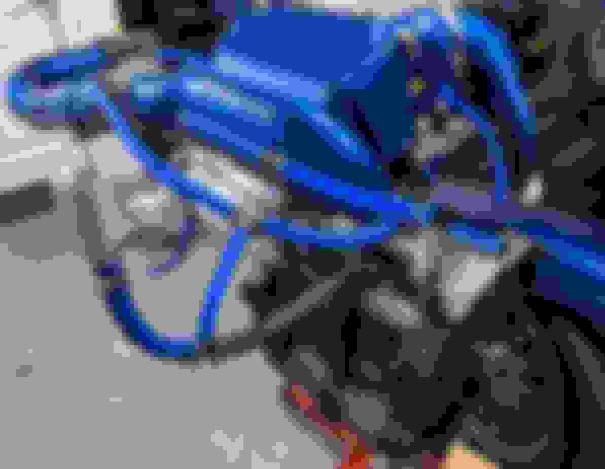
In the above two pictures, the two biggest hoses that come way out the front are the coolant loop - the shorter one connects to the higher-up located return-nipple on the rear side of the plastic coolant tank, the longer one which is attached to the front of the Pettit intercooler unit proceeds directly down to draw the cooled coolant from the Hayden coolers mounted below (in front of the radiator for most setups, but lying flat on the undertray for my specific setup). You can also see some black rubber Good Year heat-shielding on the large coolant-return hose right under the TiAL BOV - this was how it was set up on the system when I got it, so I just transferred the shielding over assuming it gets very hot in that area. (you can see it better in one of the closer-up pics below as well.
.
.
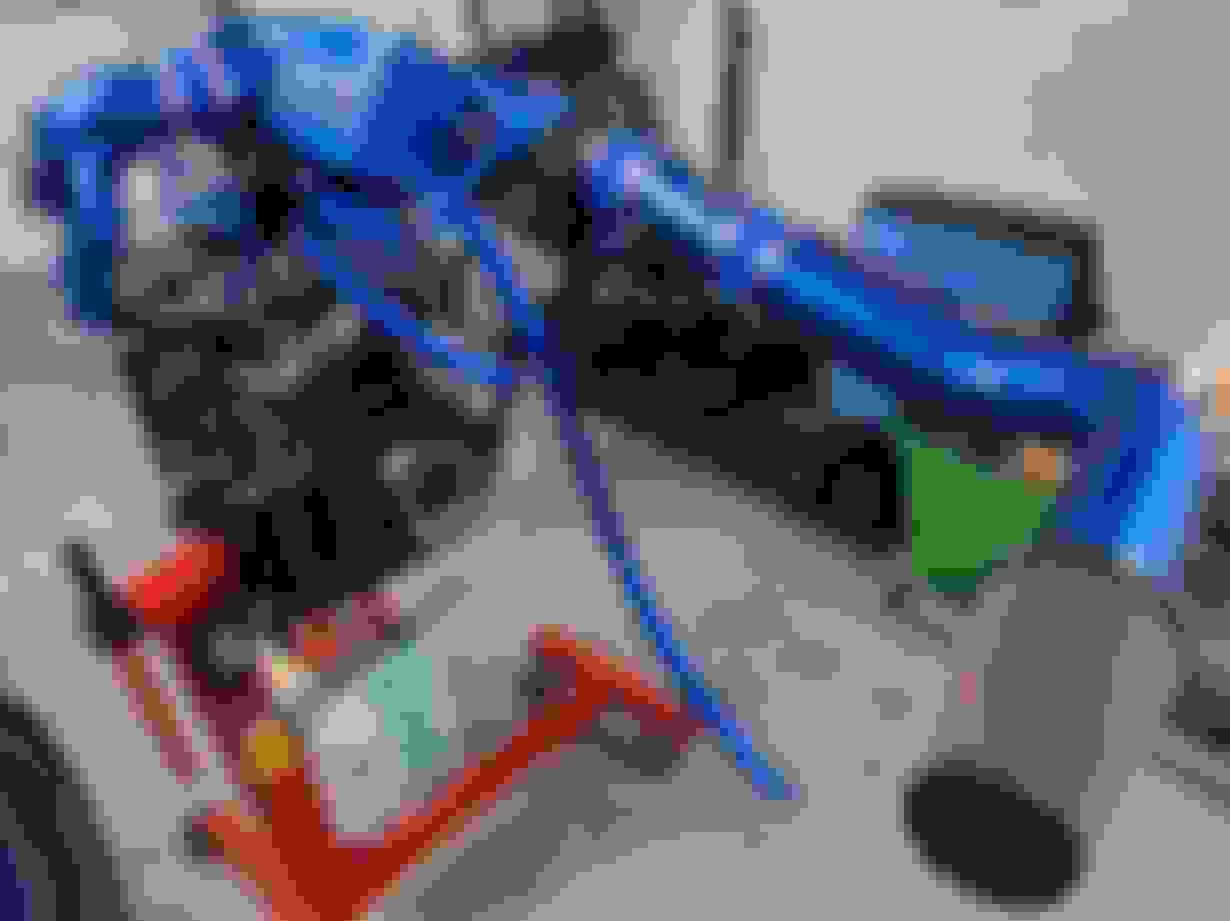
. The oil filler tip is held up for visualization purposes by a random piece of wire I found, to show how it will be mounted near the brake-booster drum in the engine bay. Here you can see the way the short little segment of vent hose connects to the oil fill-line via a T-connector on one end and then tees off again on the upper end to connect in one direction (forward) to the MAF tube while wrapping around the other direction (to the rear) all the way around the rear of the compressor and attaching to the nipple on the top/front/passenger-side of the compressor unit (where the drive-gears are that turn the twin-screws and where you fill the SC oil). It might be advisable to add heat-shielding to the oil vent line that wraps around the rear like in the pic, so it doesn't melt to the intake; my Pettit system came with that shielding so I just transferred it to the same place on my new hose as it was on the old black one, securing it in place with some electrical tape. You can also see the brake-booster line with the check-valve coming off of the intake right under the word PETTIT.
.
.
.
In this pic and the one directly above it, you can see where the jet-air hose (black hose pointing straight down lying on the top-left side of the engine block) and oil-metering hose (curved, sort of question-mark shaped black hose pointing towards the rear) combine via T-fitment into a singular (blue) hose which leads to the top nipple of the throttle body.
.
.
. Here's an underside shot to illustrate how the little short vent hose leaves the downward-facing throttle-body nipple and leads to the passenger/inboard side of the MAF housing, essentially sucking air from the jet-air and oil-metering hoses through the throttle-body (where coolant used to go) and into the MAF housing to be recirculated. Later on I also realized there was some heat-shielding on the original black hose that went here to shield the hose from the throttle-body's heat, so I transferred that over.
.
.
.
At this point, the only thing I am missing is a tune and a way to install it; MazdaEdit for ~$250, Tactrix dongle for ~$170, and ~$450 (350 pounds sterling) for Carl Ryan to tune it. Unfortunately I don't have upwards of a thousand dollars sitting around so I'll have to buy it in pieces over the coming weeks but I also won't really have any big lump of free time in the coming month or two anyway, so I will just work on getting the final pieces together and then hopefully install in the early fall! Really looking forward to you guys' completed setups too, as we stride ever closer to the home stretch and the promised land of having actual, notable horsepower in our RX8's!
Last edited by OtherSyde; Jun 7, 2019 at 05:13 PM.
LOL, yeah dude, there is an entire DIY thread dedicated to this "Mod"
Oh yeah I know, I read it; that's why I didn't really post many pics or go into any real deep explanation - I really only noted it because it's not a random "mod" for the SC guys but actually a required part of the Pettit SC installation, and doing it preemptively will make the actual install go smoother once I get to it. You've got a turbo right? Out of curiosity, did you have to do this for your turbo build?
Also, hopefully you don't mind, but every time I mention my pending SC setup anywhere (Facebook, Reddit, etc.) people immediately start arguing with me about how it's a doomed prospect and any boost, especially a turbo, is just absolutely guaranteed to blow your Renesis within a year or two, and I keep holding you up as an example of someone who has run a turbo (at 7psi, right..?) for literally years and dozens of thousands of miles without any real problems due to good supporting mods, maintenance, and a stable tune. I might be accidentally making you into an RX8 turbo celebrity, so in case a bunch or newbies start showing up to ask you questions about your setup, I apologize in advance. Honestly I doubt it will happen though; most of these are these are the kind of idiots who can't even be bothered to read the updated information that's already out there for them to read, let alone go locate some specific person on a forum to ask for actual experienced, sensible advice instead of blindly following their bias-confirming groupthink. Maybe you can dispense wisdom and save a few Rennies though, who knows?
Last edited by OtherSyde; Jun 7, 2019 at 05:17 PM.
The biggest reason why I would be coming over here is the group of all of you currently in here aren't just doing your own builds, but you are making them VERY clean setups. I plan to do the same with my turbo build. I've been getting lots of ideas thanks to you all.
I'm going to be doing some major retouting of the smaller coolant lines/system for our motors, simplifying the systems (somewhat), and relocating a custom coolant tank to the firewall where the wiper fluid tank normally resides.
I already have a custom wiper fluid tank that will be in the far corner against the firewall and body of the car, next to the coolant tank. I will have a oil catch can mounted near the secondary air injection pump close to where the factory battery sits. Battery is relocated to between the rear seats.
Xero, I know this is the Pettit thread, but it always helps to bounce ideas back and fourth. If you want opinions on anything related to your turbo build that we can help with, I'm sure everyone here would be happy to help. Maybe you can be an "honorary member" here!
Well, I've been bouncing some ideas off Brettus for my next mod/project.
Right now I am making a custom coolant tank that will be relocated over to the firewall where the wiper fluid tank normally goes. I already have a custom wiper fluid tank that will be back in the corner with the coolant tank. Setup may look similar to the "sohn" system, except my tanks will both be aluminum.
This will simplify the hose routing, as well as remove extra hoses. This will also be convenient for me since I'm going to turbo my car and will use the TB hose to feed the turbo and just have it return straight up to the coolant tank. I will be removing at least 3 hoses from the factory coolant system, if not more.
I have my battery relocated to the trunk, EPS fuse relocated to the fuse box, Mazdaspeed intake (will be getting replaced since I will have turbo piping instead), and I cut out the beam that the factory intake tray and battery normally sit on. I have TONS of room now behind the radiator so lets see how my build develops. I will be using a Greddy Manifold and Greddy turbo (likely upgraded), but I am going to be rebuilding the motor and doing a lot of little upgrades and mods along the way.
I don't want an engine bay that looks like a mess, so having things look aesthetically pleasing is very important to me. I'm looking forward to what the end result will be. I wont be creating a build thread until I have all the supplies to rebuild my engine, which I should hopefully have by the end of July. Fingers crossed
You've got a turbo right? Out of curiosity, did you have to do this for your turbo build?
Also, hopefully you don't mind, but every time I mention my pending SC setup anywhere (Facebook, Reddit, etc.) people immediately start arguing with me about how it's a doomed prospect and any boost, especially a turbo, is just absolutely guaranteed to blow your Renesis within a year or two, and I keep holding you up as an example of someone who has run a turbo (at 7psi, right..?) for literally years and dozens of thousands of miles without any real problems due to good supporting mods, maintenance, and a stable tune. I might be accidentally making you into an RX8 turbo celebrity, so in case a bunch or newbies start showing up to ask you questions about your setup, I apologize in advance. Honestly I doubt it will happen though; most of these are these are the kind of idiots who can't even be bothered to read the updated information that's already out there for them to read, let alone go locate some specific person on a forum to ask for actual experienced, sensible advice instead of blindly following their bias-confirming groupthink. Maybe you can dispense wisdom and save a few Rennies though, who knows?
I just have my hoses looped together (the stock GReddy turbo is not water cooled) but I will be using them when I upgrade to the BNR turbo (water cooled).
And not a problem man, I get all sorts of questions on Instagram when people find out it is turbo'd so I'll be ready for it haha. Yes you're right, I've been running between 7 and 9 PSI since 2010 on stock engine putting about 65,000kms (42,000 miles) of boost on it. I blame 90% of my "success" on Brettspeed tuning and the other 10% to keeping a close eye on oil/coolant temperatures, AFR's, and Fuel pressure. I'm also lucky to live in a colder climate so keeping it cool isn't as big of an issue for me.
All of you guys doing the SC thing right now is pretty cool, great that you guys have each other to bounce ideas back and forth off of. They all look like super clean well done builds so far, so I hope you guys have some real success with the final product!