
my grounding kit results


Administrator
Joined: Jul 2002
Posts: 21,958
Likes: 115
From: portland oregon
in retrospect im not suggesting that thing in the last link i provided- i was just copying it from team rx8s post to discuss it. i dotn see how its worth a hundred bucks or why that plate is needed either.


Momentum Keeps Me Going
Joined: Sep 2002
Posts: 5,036
Likes: 5
From: Colorado
I know there is a ground wire for each coil. But what are you saying? Do you think the existing coil wiring grounds be ALSO grounded to the plate that's there - to do what zoom is talking about ?

Charlie....can you find out what they are doing to " ground" the coils better from the "source" 
From re-reading the quote above it says coil harness....???
From re-reading the quote above it says coil harness....???
Last edited by dannobre; Aug 13, 2006 at 06:55 PM.
Momentum Keeps Me Going
Joined: Sep 2002
Posts: 5,036
Likes: 5
From: Colorado
olddragger I don't think there is much to it, but it's going to be a bit messy. The grnd wire is one of the 3 wires in the plug that goes in the socket on each coil. To get the advantage of improved grnding, you'd need to splice into each grnd at the coil, then join them and just go back to the battery. Prob use like 6/8/10? guage wire. I'd be concerned about breaking the insulation seal, but it'd prop be ok.
I used a 4wire weatherproof connector.....and spliced into the ground on all 4 coils.....then connected the other end to an 8 gauge back to the battery. I used a connector that I had lying around, and waterproof heat shrink to seal the splices. Took about 1.5 hours.
I used the connector so that it could be disconnected like the OEM plugs if it needed to be removed.
There really isn't any difficulty if you are competant with a soldering iron. It is a bit of a PIA to get to the wiring harness though
I used the connector so that it could be disconnected like the OEM plugs if it needed to be removed.
There really isn't any difficulty if you are competant with a soldering iron. It is a bit of a PIA to get to the wiring harness though

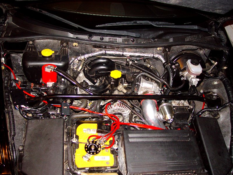
My $5 e-bay grounding kit arrived today. I unpackaged and installed it in about 45 minutes, which includes time to take resistance measurements and pictures.
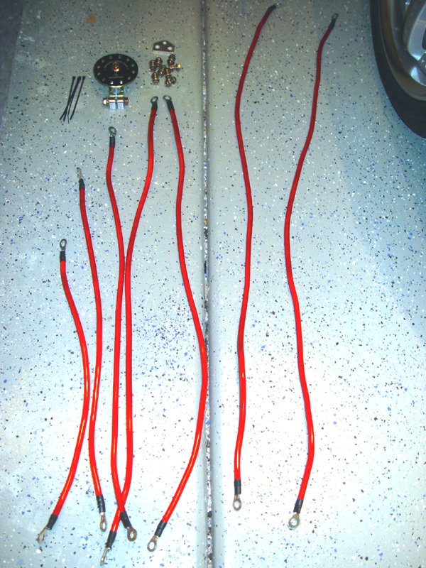
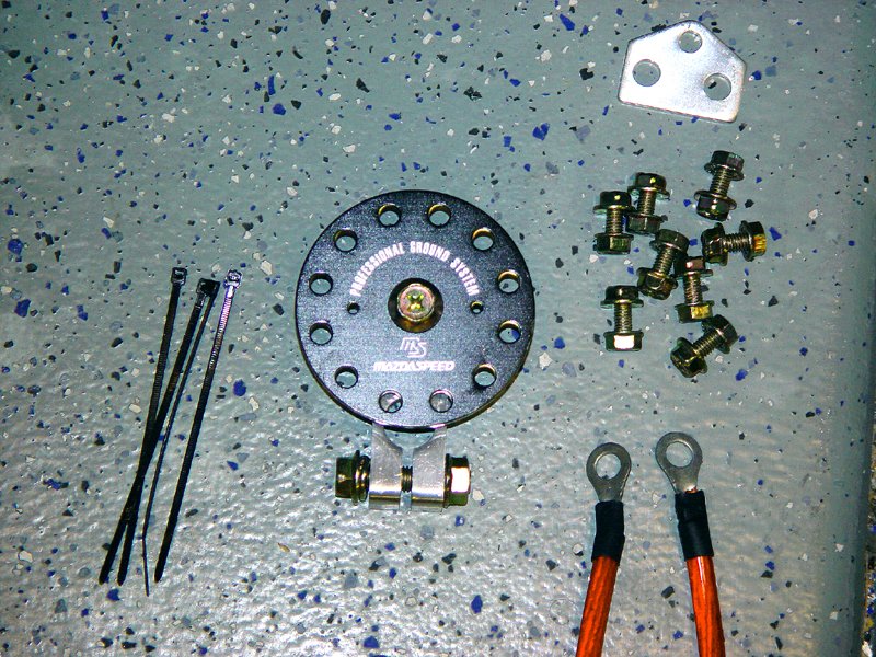
The kit includes 7 wires pre-crimped and heat shrink wrapped to lugs. Also included is a new battery ground terminal, a distribution block (with a fake MazdaSpeed logo on it!), a set of 10mm nut/bolt combinations, a 2-1 lug and some wire ties.
First I attached the new terminal (after cleaning the post).
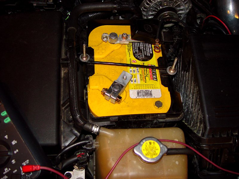
Then I attached the distribution block and the two existing ground wires via the 2-1.
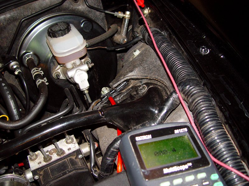
I then measured the resistance to the chassis ground buy the washer bottle to the negative terminal as a baseline. The amount of resistance to ground from this point in the chassis is considerable at 4.7 ohms.
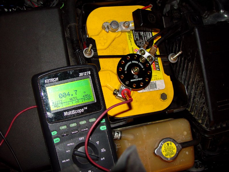
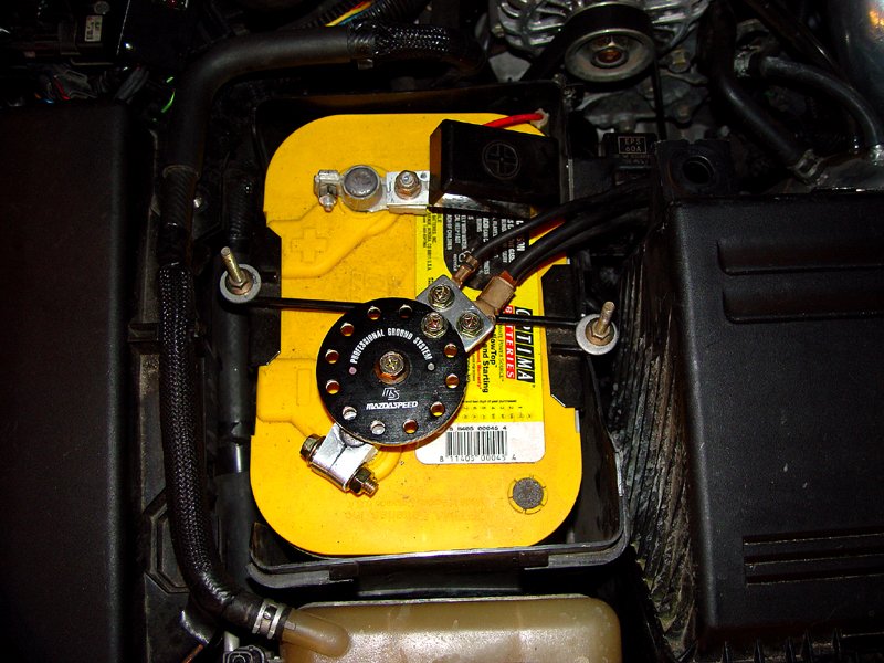
I then attached the first wire to this point on the chassis to the distribution block.
Then I re-measured the resistance from the ground point right next to the one just connected (to get the actual change in grounding at this point rather than what is being carried directly by the wire). The resistance had dropped to .4 ohm! 1/10 the original resistance.
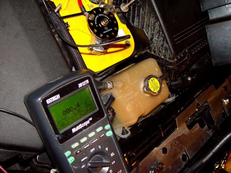
Then I measured he resistance on the other since of the chassis. It was down to .5 ohm. So, I connected the second wire to the area near the strut tower on that side.
The resistance dropped to .4 ohm.
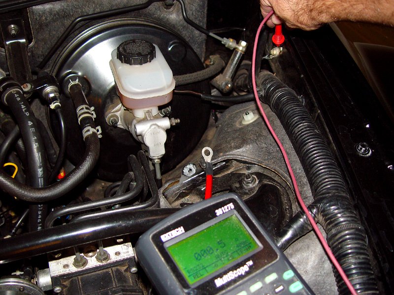
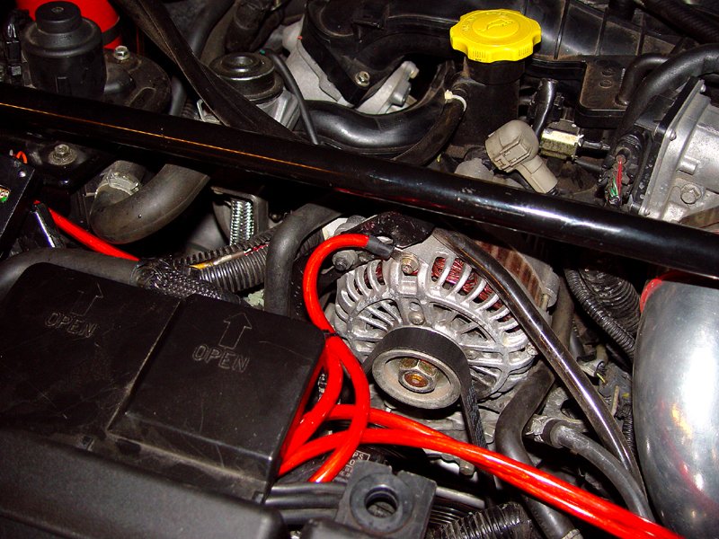
Next was the alternator. This dropped the resistance across the accesible parts of the front of the engine block from .4 ohm to .2 ohm.
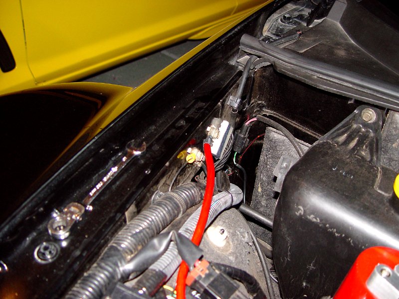
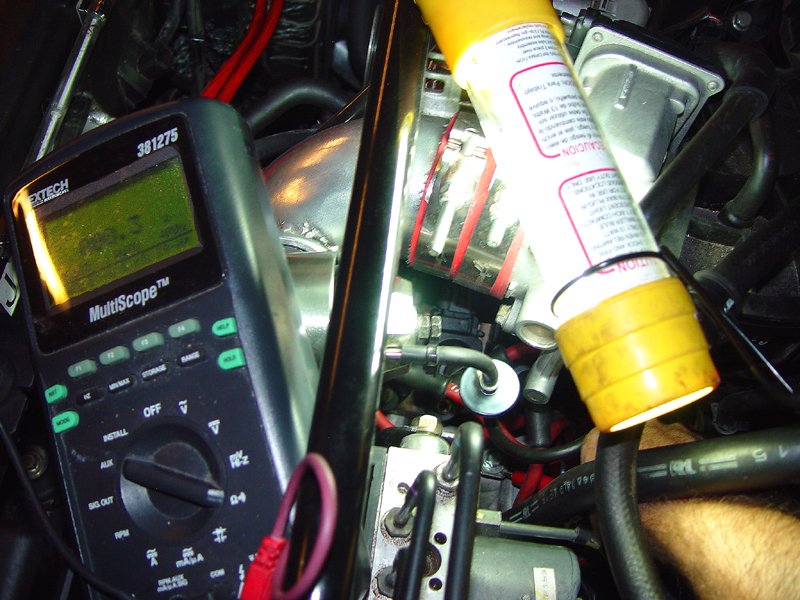
Last, I hooked up a wire to the plate to which the coils are mounted. I used the open mounting point where the part of OEM wiring harness used to be. I think this carried the wire for the VFAD with a plastic clip.
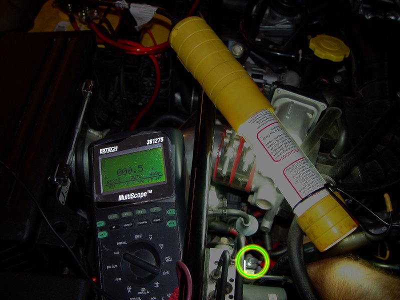
The resistance dropped from .5 ohm to .3 ohm.
The final result was this red cobweb of wires. With the battery cover back in place, it is pretty neat looking.
Results?
As far as I can tell, the idle is more stable - it now sits squarely at 820 RPM without the usual 50 RPM wander. Hitting my fan on switch (I had wired a switch that allows me to turn the fans on full at any time - you would be surprised how stingy the PCM is with the fans in the OEM configuration. Here in the desert, they really need to be on all of the time), I noted NO drop in RPM. The load used to take the RPM down a notch as the alternator (generator) fought to keep up.
Whether any of this produces any more power I can't say. However, I would imagine that is things are easier for the generator, there should be less loss. Also, making it easier for the coils to fire can't hurt.
I'd post a DIY, but since you can't put pictures in the DIY section, why bother.
The kit includes 7 wires pre-crimped and heat shrink wrapped to lugs. Also included is a new battery ground terminal, a distribution block (with a fake MazdaSpeed logo on it!), a set of 10mm nut/bolt combinations, a 2-1 lug and some wire ties.
First I attached the new terminal (after cleaning the post).
Then I attached the distribution block and the two existing ground wires via the 2-1.
I then measured the resistance to the chassis ground buy the washer bottle to the negative terminal as a baseline. The amount of resistance to ground from this point in the chassis is considerable at 4.7 ohms.
I then attached the first wire to this point on the chassis to the distribution block.
Then I re-measured the resistance from the ground point right next to the one just connected (to get the actual change in grounding at this point rather than what is being carried directly by the wire). The resistance had dropped to .4 ohm! 1/10 the original resistance.
Then I measured he resistance on the other since of the chassis. It was down to .5 ohm. So, I connected the second wire to the area near the strut tower on that side.
The resistance dropped to .4 ohm.
Next was the alternator. This dropped the resistance across the accesible parts of the front of the engine block from .4 ohm to .2 ohm.
Last, I hooked up a wire to the plate to which the coils are mounted. I used the open mounting point where the part of OEM wiring harness used to be. I think this carried the wire for the VFAD with a plastic clip.
The resistance dropped from .5 ohm to .3 ohm.
The final result was this red cobweb of wires. With the battery cover back in place, it is pretty neat looking.
Results?
As far as I can tell, the idle is more stable - it now sits squarely at 820 RPM without the usual 50 RPM wander. Hitting my fan on switch (I had wired a switch that allows me to turn the fans on full at any time - you would be surprised how stingy the PCM is with the fans in the OEM configuration. Here in the desert, they really need to be on all of the time), I noted NO drop in RPM. The load used to take the RPM down a notch as the alternator (generator) fought to keep up.
Whether any of this produces any more power I can't say. However, I would imagine that is things are easier for the generator, there should be less loss. Also, making it easier for the coils to fire can't hurt.
I'd post a DIY, but since you can't put pictures in the DIY section, why bother.
Last edited by MazdaManiac; Aug 17, 2006 at 04:10 PM.

Goat rider
Joined: Feb 2006
Posts: 587
Likes: 0
Did you not ground the throttle body? Some people are pretty sure it will help throttle responce, while others say it wont. After all it is electronic and bolted to plastic. If you got an extra wire go for it!
BTW 2 RX-8's? nice.
BTW 2 RX-8's? nice.

Registered Lunatic
iTrader: (1)
Joined: Aug 2003
Posts: 3,591
Likes: 49
From: SF Bay Area, California
Jeff, this is great stuff - shows that the grounding kit indeed has some positive effect.
Huh? Five bucks? Isn't that a typo?
Strange... the DIY section is full with posts including pictures - or do you mean that you can't use the [IMG] tag, only attachments are allowed?
Originally Posted by MazdaManiac
My $5 e-bay grounding kit arrived today.
I'd post a DIY, but since you can't put pictures in the DIY section, why bother.

One ball, corner pocket
Joined: Apr 2004
Posts: 2,053
Likes: 1
From: Fontucky, right next to Patriotville
great job.....forget the DIY...anyone who really wants this mod is already in this thread anyway. Thanks for the pics and the pre/post measurements. You have a link to the vendor you used on Ebay. I have some Paypal money from selling my rear aero flares I would like to spend

Thread Starter
Registered
iTrader: (3)
Joined: Apr 2004
Posts: 10,828
Likes: 40
From: macon, georgia
Great work MM. I am glad you have now satisfied all the folks that require scientific proof to believe us deductive reasoning folks. I have the same kit except my grounding plate is gold.
OD
OD
Originally Posted by olddragger
Great work MM. I am glad you have now satisfied all the folks that require scientific proof to believe us deductive reasoning folks. I have the same kit except my grounding plate is gold.
OD
OD
Originally Posted by Tamas
Huh? Five bucks? Isn't that a typo?
http://cgi.ebay.com/ebaymotors/ws/eB...BSAA%3AUS%3A11
Originally Posted by Tamas
Strange... the DIY section is full with posts including pictures - or do you mean that you can't use the [IMG] tag, only attachments are allowed?
Originally Posted by zoom44
nice job jeff. thanks.
the point of no image tags is so that the pics stay with the thread. with linked photos they could easily get "lost"
the point of no image tags is so that the pics stay with the thread. with linked photos they could easily get "lost"
The problem with the thumbs at the bottom of the post is that they don't follow the narrative. Its hard to go step-by-step and then say "go look at all of the pretty pictures and figure out whey I snapped one of that hidden bolt in the corner and why its the third pic in the group".


I was thinking the same thing when I saw the bright red wires used for ground.
Silver should be okay right?
I have about the same kit that Mazdamaniac has but since I will be adding a sub setup I am adding a different negative post and will pull off of that. When I bought the post I also got a distribution block for the ground I may use that in the engine bay. And bump up to 4 gauge wire as I have 200 feet of it in bulk.
I went with red because it is a theme on my car.
Besides, even the positive battery connection is black, so red wiring in this context is meaningless. If I am carless enough to try to use a grounding wire as a power source, I deserve the fireworks display I get...
Besides, even the positive battery connection is black, so red wiring in this context is meaningless. If I am carless enough to try to use a grounding wire as a power source, I deserve the fireworks display I get...
Originally Posted by MazdaManiac
I went with red because it is a theme on my car.
Besides, even the positive battery connection is black, so red wiring in this context is meaningless. If I am carless enough to try to use a grounding wire as a power source, I deserve the fireworks display I get...
Besides, even the positive battery connection is black, so red wiring in this context is meaningless. If I am carless enough to try to use a grounding wire as a power source, I deserve the fireworks display I get...
 You should be okay as the grounding system says grounding system on top and the big positive and negative signs on the Optima battery. For those that have their vehicle serviced by someone else it may be a good precaution to not go with red though.
Fireworks are cool just hate the feeling after when I feel like I got shocked but it is just guilt as to being so stupid for doing that.


Funny but some of the electrical systems on the equipment I work on have ground wires in red and brown and positive wires in black.
I hate looking at those schematics.
The equipment is manufactured in Germany and I have never seen such a wiring nightmare.
So the moral of the story is ,,,Never assume a wire is Pos. or Neg. by color.
I hate looking at those schematics.
The equipment is manufactured in Germany and I have never seen such a wiring nightmare.
So the moral of the story is ,,,Never assume a wire is Pos. or Neg. by color.


Go Texas Longhorns!
Joined: Apr 2003
Posts: 1,818
Likes: 1
From: Houston, Texas
Nice job jeff, do you think it would matter if you daisy chained the setup rather connecting each point to the battery? I don't have that plate and I have one connection to the battery that then connects to the other points.
I may look into this setup though.
I may look into this setup though.