When you click on links to various merchants on this site and make a purchase, this can result in this site earning a commission. Affiliate programs and affiliations include, but are not limited to, the eBay Partner Network.
HOWTO: Cure LED Turn Signal Hyperflash - Flasher Unit Capacitor Replacement
Installing LEDs in your turn signals will almost always cause a high-speed flash. I don't like cutting/splicing wires to install load resistors, and it's much easier to change out a capacitor anyway. I don't have enough posts to put this where it should probably go, so maybe one of the mods can move it for me. Credit to felgood90210 for the idea, but the photos wouldn't show up for me, and I have a few notes that'll make it easier on the next guy. By far, the hardest part is just reinstalling that blasted screw.
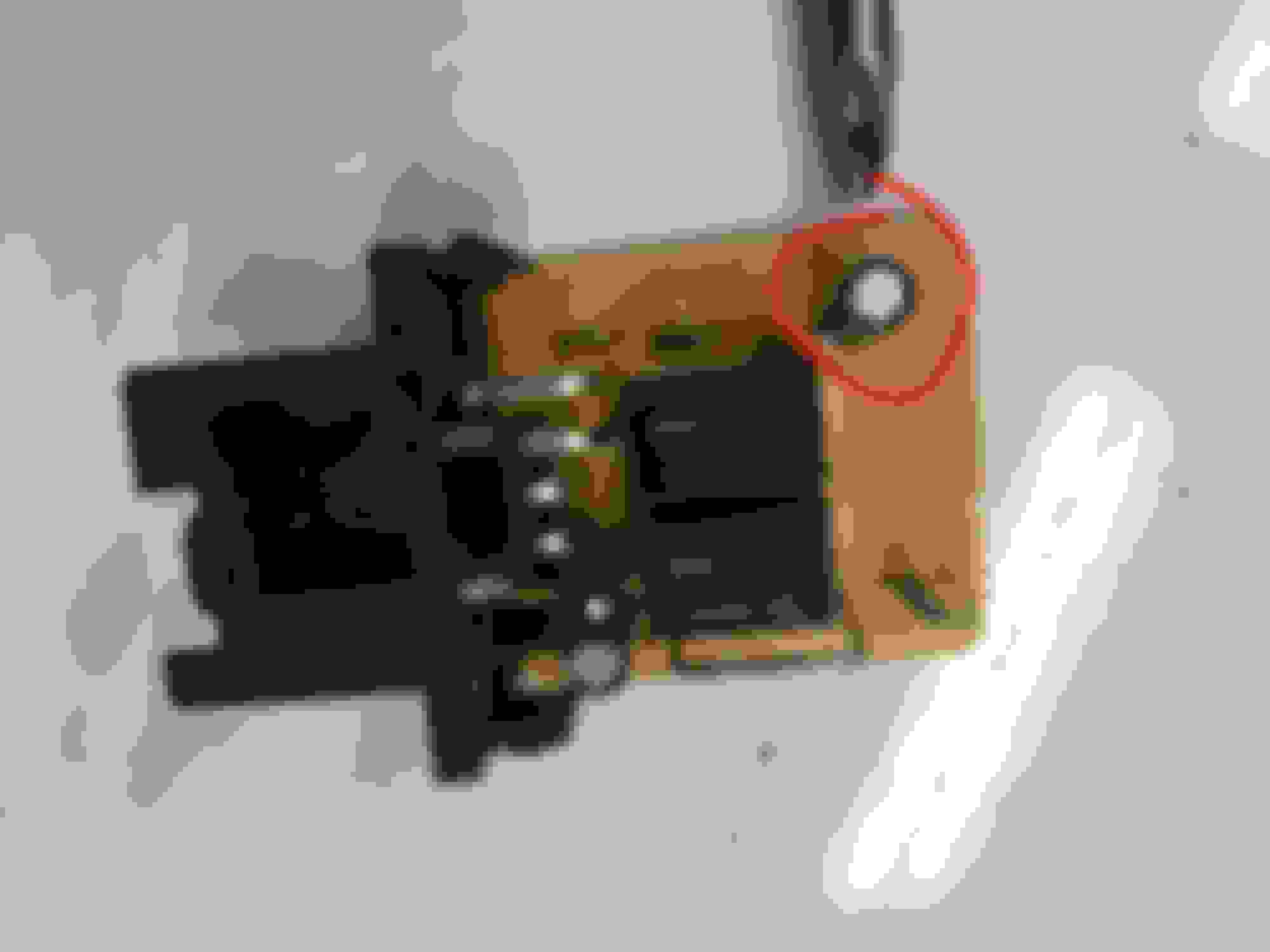
Flasher unit is found under the driver's side dash (US Spec) just above the hood/trunk release. There's a single philips head screw on the door side of it. Remove this screw. Photo is taken from the pedals shooting toward the back of the car. The bracket has two holes in it; note that the 2nd hole is for the alignment peg.
After you remove the screw, you'll be able to get a better view of the connector. Unplug the connector, and the relay will be free.
Now that the relay is out, you have to pull the board out. Pry from the connector side between it and the wall with a small pick or screwdriver from both sides and wiggle the board out.
Additional view of the tabs released.
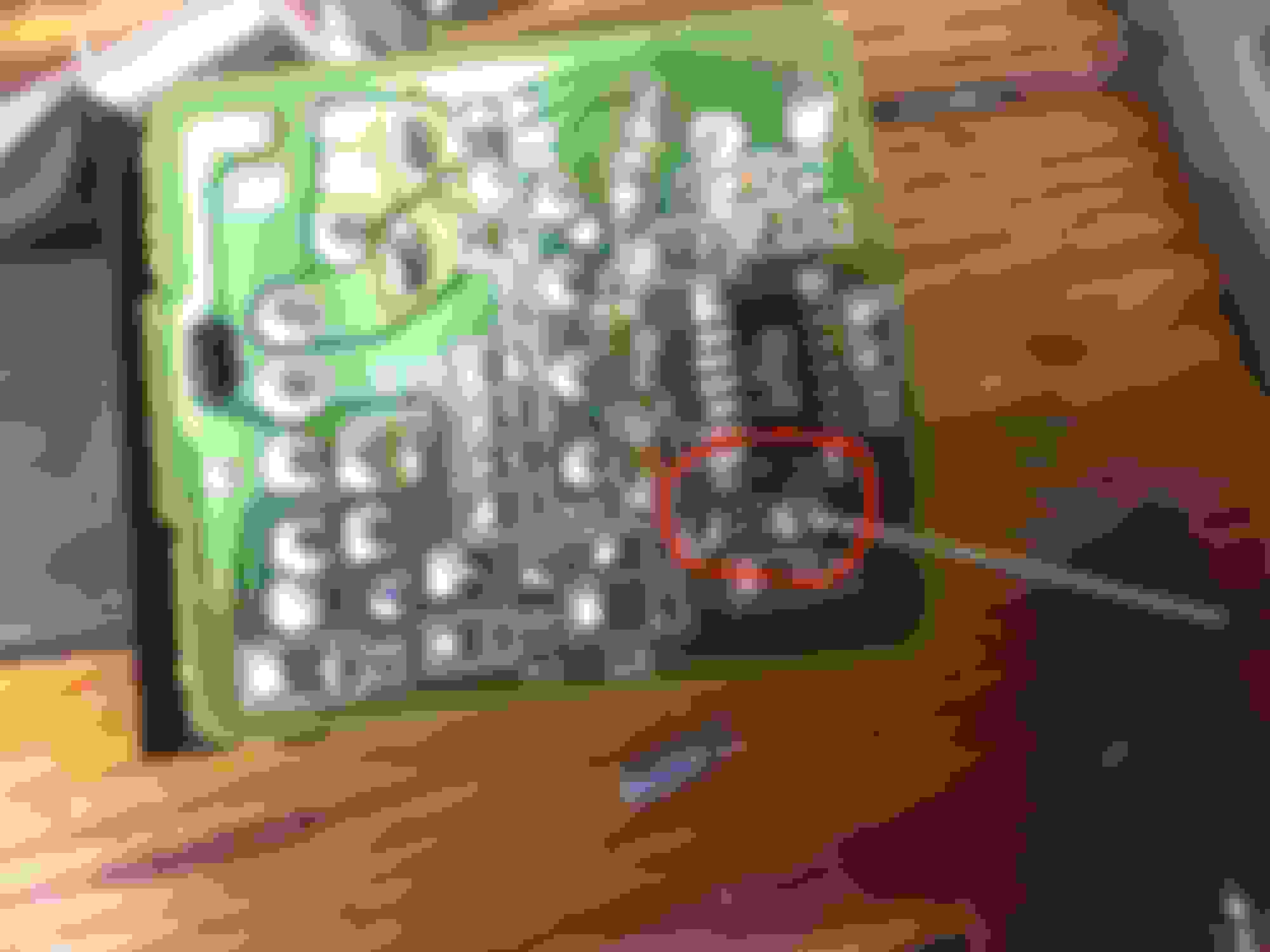
C1 is what we're going to replace. Note that the striped side of the cap matches up with the white mark on the left hole.
This photo is taken after removing the cap and inserting the leads for the new one. From the back side of the board, alternate heating up each of the two solder pads and wiggling the capacitor away from the board. The solder was very soft on mine, so it didn't take much heat at all to free it.
I replaced it with a 10uF 100V Rubycon cap. 10uF is the important part. The labeled voltage is just the max the cap rated for; I happened to have some 100V ones laying around. But don't go below what was removed (50V).
After soldering in the new cap, trim the leads, slide the board back in the case, connect it back in the car, but DO NOT install the screw yet. Test it first. If all is good, then move on to the frustrating part--putting that screw back in. The alignment pin allows the bracket to rotate, so even with my small hands it was a pain to get it tightened back down.
I talked too fast. It still flashes faster with LEDs than with incandescent, though I think it doesn't flash as fast as it did before. I've patched everything up so I can't easily test if removing a bulb causes it to flash even faster.
Maybe it needs an even bigger capacitor. Anyway I'll leave it as is now it's not unusably fast
Do you think this rate is okay, or should I try grounding pin 8 as in the other thread. I don't like the idea of not having a malfunction indicator and I'm seeing on the other thread that flashing is faster even with shorting pin 8.