
The GOODbox


Don't really know! The gauge was a Glowshift (excellent for the money, btw), but I'd still had the sensor from a no-name ebay gauge kit that I tossed. I checked the Glowsport calibration with that sensor and it was okay, so just reused it (lazy?).
These, and most other cheap temp sensors are simple resistors where the resistance decreases as the temperature increases. They are used as part of a gauge circuit where the power to run it comes from the gauge. The calibration will depend on how the manufacturer chose to set up the gauge. What I did was use my existing aftermarket gauge (that I was going to keep in the car) to sample the voltage of that circuit with the Goodbox. The Goodbox will not work with this type of sender and without an already-installed gauge, unless you build up a powered circuit for it to sample.
Some of the more expensive sensors include a wire for +5v input, but output a 0-5v directly from the sensor, which the Goodbox can use directly. You have to build a little 12v-->5v power supply to power them, but that's simple (as I've described in an earlier post), plus if you want to add sensors, without adding gauges, you can easily do so and power them from the same +5v supply, assuming you use these +5v powered sensors.
I believe from HiFlite999's posts he has only hooked up the pressure sensor and is using this one http://www.aemelectronics.com/150-ps...sensor-kit-659 .
To further this discussion I used my google skills and found the following, looks like they should work:
1/8" 150 psi pressure sensor - needs 5v input voltage - HiFlite999's R-Shack solution?
http://www.aeroforcetech.com/products_sensors_oil.html
manual http://www.aeroforcetech.com/files/A...g_Oil_Fuel.pdf
3/8" kit with 5v regulator for output, uses 12v input.
http://www.aeroforcetech.com/products_sensors_temp.html
manual http://www.aeroforcetech.com/files/A...structions.pdf
Manuals have the factors needed for the conversion of volts to psi and degrees.
$109.95 plus a sandwich plate and we should be in business, thoughts? I'll probably be the guinea pig but not for another month or two, have something else I should be focusing on.
 ) The second is nice in that it includes the 5v power supply.

Anyone think this is a viable option for oil temp measurement?
http://www.aemelectronics.com/water-...sensor-kit-639
http://www.aemelectronics.com/water-...sensor-kit-639
Rule of thumb: sensor with 1 or 2 wires = nope! (without further engineering)
I'm interested to see the temp sending unit the HiFlite used because the AEM is $40 and the prosport is $10 http://prosportgauges.com/temperature-sender.aspx
Rule of thumb: sensor with 1 or 2 wires = nope! (without further engineering)

Alright well the pull up resistor value is 'fairly' trivial and doesn't need to be too exact. What we do need to know is the current handling capability of the GoodBox's aux input. In the datasheet schematic the purpose of the pull up is to provide a voltage divider and a short circuit barrier. If the sensor happens to go into a state whereby the resistance is effectively 0 ohms then the resistor between Vcc and Gnd will dissipate that excess current.
The way we should choose that resistor value is by our knowledge of what the Goodbox's ADC's current handling capability is. For a 5V circuit with a....10k resistor, let's say, if that sensor goes into a state of 'shorted' then the ADC will only have to handle a short circuit current of .5mA. But if the pull up was 10 ohms then the ADC would have to dissipate 500mA, not such an easy task.
For more of an explanation here is a temp sensor I used on a project not long ago. TMP36
http://www.analog.com/static/importe...MP35_36_37.pdf
This sensor is powered by a 2.7-5.5V source and has a range of -40C -> +125C. Every degree increase will correspond to a 10mV increase in output. At -40C the output is 100mV. At 0C the output was 500mV etc...
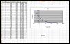
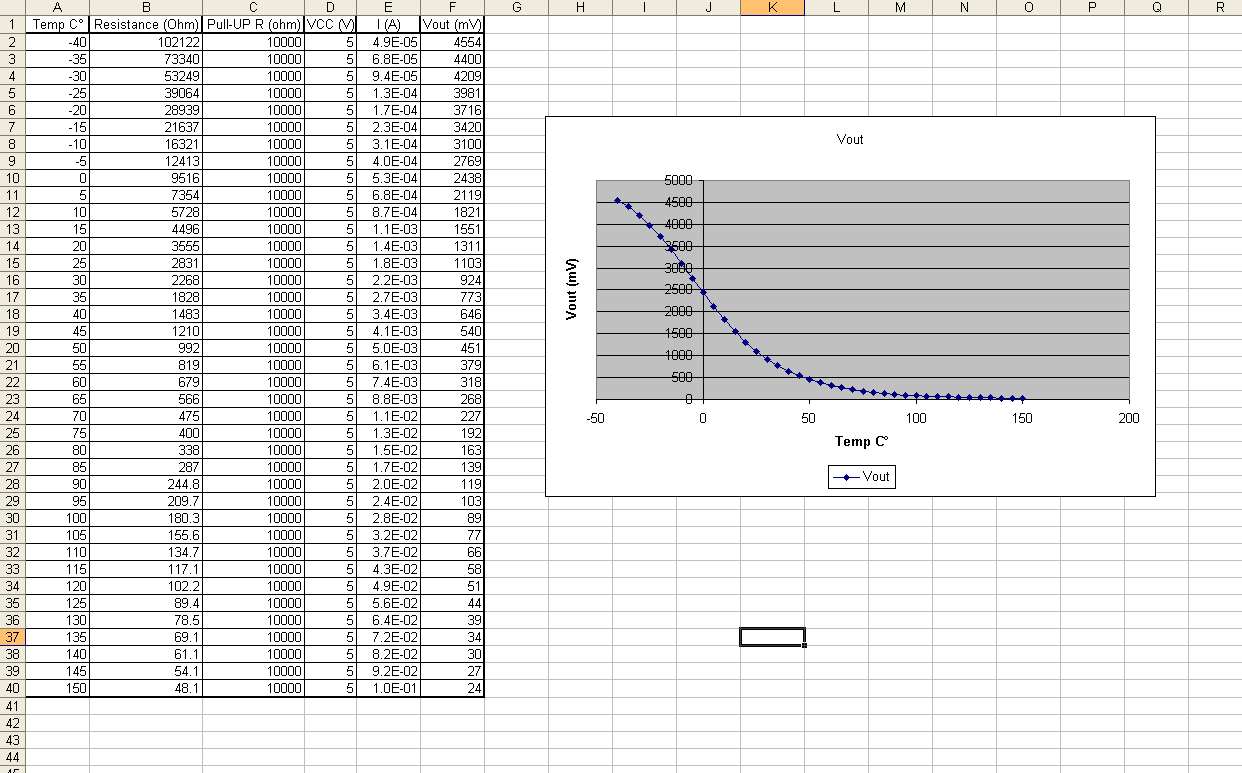
I went ahead and mapped out the voltage outputs if the AEM sensor were to be used and saved it in excel. According to my calculations if a 10Kohm resistor was used as a pull-up the max current the ADC on the Goodbox would see is 100mA. The resolution this combo would have (5V reference and 10bit ADC would give a resolution of .5�C.
The way we should choose that resistor value is by our knowledge of what the Goodbox's ADC's current handling capability is. For a 5V circuit with a....10k resistor, let's say, if that sensor goes into a state of 'shorted' then the ADC will only have to handle a short circuit current of .5mA. But if the pull up was 10 ohms then the ADC would have to dissipate 500mA, not such an easy task.
For more of an explanation here is a temp sensor I used on a project not long ago. TMP36
http://www.analog.com/static/importe...MP35_36_37.pdf
This sensor is powered by a 2.7-5.5V source and has a range of -40C -> +125C. Every degree increase will correspond to a 10mV increase in output. At -40C the output is 100mV. At 0C the output was 500mV etc...
I went ahead and mapped out the voltage outputs if the AEM sensor were to be used and saved it in excel. According to my calculations if a 10Kohm resistor was used as a pull-up the max current the ADC on the Goodbox would see is 100mA. The resolution this combo would have (5V reference and 10bit ADC would give a resolution of .5�C.
Last edited by Lord ET; Aug 18, 2010 at 02:02 PM.
If I hadn't JUST done a temp sensing project I may have been a little more confused about this. However, I see no reason that the AEM sensor wouldn't work. After the Goodbox current limit is established we can choose an appropriate pull up and then remap the voltage vs temperature curve. When we know that then we can establish an approximate slope that the Goodbox is looking for.
I got the cycling display this morning. A/C was on when the car was shut off for gas. When I turned the car back on there was no 'greeting' it just began cycling through all possible lights on the lcd. My battery is less than a month old and still has plenty of juice.
I took a video of it.
I turned the car on and saw the cycling display
I turned off the A/C with no change
I tried pressing the buttons on the GoodBox with no change
Then I shut the car off
Turned it back on and I was 'greeted'
Then the unit functioned normally.
I think the mode the GoodBox was in was deal speed/rpms and I think on gauge B
http://www.youtube.com/watch?v=rU4MPrqATKo
Last edited by Lord ET; Aug 19, 2010 at 08:56 AM.

Registered
Joined: May 2005
Posts: 300
Likes: 3
From: Eastern Ontario
If I hadn't JUST done a temp sensing project I may have been a little more confused about this. However, I see no reason that the AEM sensor wouldn't work. After the Goodbox current limit is established we can choose an appropriate pull up and then remap the voltage vs temperature curve. When we know that then we can establish an approximate slope that the Goodbox is looking for.
@pieter3d
1- What are the input impedances of the auxiliary ports (aside from the 1k filter)?
2- What are the sampling rates of the auxiliary ports?
3- You suspected a 1 volt drop from the 5 Ohm resistor (~200 mA), but SC-ed measured about a quarter of this. Say you are right in that the slot machine effect is noise related. Then the higher the resistance the better. Say SC-ed is right in that the current draw is only about 50 mA. Let's say we want to limit the voltage across this resistor to 1 volt. Then one could use a standard half-Watt 22 Ohm resistor for improved noise immunity. Comment?
4- 9krpmrx8 mentioned that he wishes the Goodbox could display system voltage. Although it is pretty simple to do this using an auxiliary port, it would also be a waste of a port since this information should be contained within the OBD system. You said somewhere earlier that you might be adding other data as you figured out how to extract it. If you do this, will you be providing a reflash service for older units?

The Goodbox current limit has virtually nothing to do with the pullup resistor, the former is simply a voltmeter. So choose the resistor, and then show how you are going to deal with the resulting non-linear voltage.
@pieter3d
1- What are the input impedances of the auxiliary ports (aside from the 1k filter)?
2- What are the sampling rates of the auxiliary ports?
3- You suspected a 1 volt drop from the 5 Ohm resistor (~200 mA), but SC-ed measured about a quarter of this. Say you are right in that the slot machine effect is noise related. Then the higher the resistance the better. Say SC-ed is right in that the current draw is only about 50 mA. Let's say we want to limit the voltage across this resistor to 1 volt. Then one could use a standard half-Watt 22 Ohm resistor for improved noise immunity. Comment?
4- 9krpmrx8 mentioned that he wishes the Goodbox could display system voltage. Although it is pretty simple to do this using an auxiliary port, it would also be a waste of a port since this information should be contained within the OBD system. You said somewhere earlier that you might be adding other data as you figured out how to extract it. If you do this, will you be providing a reflash service for older units?
2- Sampled at the same rate as OBD2 gauges, about 4x per second.
3 - I was just guessing about 1V. Seems the GB is more power efficient than I thought
 . It isn't necessarily better to have a higher drop. The idea is just to limit the current due to voltage spikes. But a higher value won't hurt, up to a point. The input voltage to the GB should be comfortably over 7V though.
4 - the Aux ports can only measure up to 5V. Any higher and you risk damage to the analog-digital converter. The OBD2 spec doesn't specify battery voltage, so there is no way to read this over CAN.
Registered
Joined: May 2005
Posts: 300
Likes: 3
From: Eastern Ontario
How much overvoltage can the inputs tolerate?
I didn't mean to say that the system voltage would be plugged directly into the port, but rather use a resistive voltage divider. For example, a 10K in series with a 30K, and tap off the voltage from the 10K for a 0-20 Volt display.
How much overvoltage can the inputs tolerate?
How much overvoltage can the inputs tolerate?
I did some digging, looks like there is an ID for requesting something called "control module voltage", which I assume is probably battery voltage. I will try this out and let you guys know if it works.
Cool. The only reason I like this is because when i was having alternator issues my Scangauge voltage read out saved me because I saw my voltage slowing dropping as I drove and I was able to drive straight to the dealer.
Registered
Joined: Apr 2010
Posts: 63
Likes: 3
From: West Yorkshire, United Kingdom
1/8" 150 psi pressure sensor - needs 5v input voltage - HiFlite999's R-Shack solution?
http://www.aeroforcetech.com/products_sensors_oil.html
manual http://www.aeroforcetech.com/files/A...g_Oil_Fuel.pdf
3/8" kit with 5v regulator for output, uses 12v input.
http://www.aeroforcetech.com/products_sensors_temp.html
manual http://www.aeroforcetech.com/files/A...structions.pdf
Manuals have the factors needed for the conversion of volts to psi and degrees.
I practised my Excel-fu, and based on their documented slope-intercept values came up with the conversion factors needed to plug in to the GOODbox for the temperature sensor:
Temperature
Fahrenheit:
Multiplier = 271, Offset = 0
FinalValue = ((271 * RawValue) / 1000) + 0
Celsius:
Multiplier = 151, Offset = -18
FinalValue = ((151 * RawValue) / 1000) + -18
(By the way, Pieter, are the multiplier and offsets integer-only because the GOODbox's CPU can't do floating-point math? Because of this, results are about 0.5 degrees out for either.)
I'm getting tired right now, so I'll see if I can work out the factors for the pressure sensor tomorrow.

Edit: Oh, I forgot to mention: I enquired with them about whether the 5V regulator that is included with the temp sensor can be used for the press. sensor as well, and they said it comes separate (i.e. not integrated in the harness) and can supply 5V for both.
Last edited by HwAoRrDk; Aug 19, 2010 at 06:56 PM.
Registered
Joined: May 2005
Posts: 417
Likes: 2
Registered
Joined: Apr 2010
Posts: 63
Likes: 3
From: West Yorkshire, United Kingdom
Here are the conversion factors I calculated for the Aeroforce oil pressure sensor:
Pressure
PSI:
Multiplier = 183, Offset = -19
FinalValue = ((183 * RawValue) / 1000) - 19
Bar:
Multiplier = 13, Offset = -1
FinalValue = ((13 * RawValue) / 1000) - 1
kPa:
Multiplier = 1263, Offset = -128
FinalValue = ((1263 * RawValue) / 1000) - 128
With these factors, again, readings will be about +/-0.5 from actual, due to the integer-only nature of the GOODbox calculations.
Hope these values are useful to someone.

Bearded Member
Joined: Jul 2009
Posts: 77
Likes: 0
From: NYC
 Thanks for exercising your Excel-fu, I will be using them in the next few weeks. Now I just need to practice my soldering for the Aux inputs.

