When you click on links to various merchants on this site and make a purchase, this can result in this site earning a commission. Affiliate programs and affiliations include, but are not limited to, the eBay Partner Network.
Thanks for the link, I'd forgotten about that discussion. Sch40 will have slightly smaller ID (1-2mm), but the extra wall thickness will offset my lack of weld skills nicely
I'm thinking of trying to split the centre primary into two smaller ones after the eWG so I can route each smaller runner to each scroll. Space may be too tight, but I feel this'd give best performance if I can pull it off. The short radius bends should make this more feasible.
Should work . I'm thinking the benefits from the twin scroll will be less than what I'm getting but the overall flow potential will be more (assuming like for like turbines).
Had the turbo off over the weekend, prepping for the new manifold build. I've found that I'll need to have the car off the road while I build it, so I'm now putting the 8 back together until I find myself a cheap daily driver to use for a few weeks while I complete the project.
While the Greddy was off the car I did some porting of the turbine housing to see if it'd improve performance. I got so stuck into the porting that I forgot to take pics of the finished product, but I have to say, it turned out very nicely. The whole job was surprisingly enjoyable and with the OCD going right off the hook the end result was a very shiny, smooth flow path. I used an electric Dremel rotary tool for the job, starting with a cut off wheel to grind away most of the excess metal, and finished with a sanding attachment.
I also enlarged the iWG opening diameter by about 1.5mm and smoothed the flow path with the intention of getting a flatter boost profile. The WG flap still closes tightly. Will this increase boost taper at high rpm because the WG flap is more easily forced open due to it's larger exposed surface area...or will it promote turbo efficiency by releasing unwanted exhaust gas from the turbine housing more effectively, reducing exhaust back pressure and allowing more exhaust through to the turbine wheel? Will find out shortly.
Initial state of the turbine housing. See the huge mismatch at the inside corners of the flanges. Must be worth a few WHPs!
Part way through, most of the grinding is now complete. Can see some of the work that was done on the iWG opening. About to fit the sanding attachment to smooth everything out. Dremel tool in bottom right of pic.
Car should be driving again tomorrow.
Last edited by JimmyBlack; 08-22-2016 at 05:52 PM.
Car spools faster after the turbine housing porting. I had to turn down the duty cycle on the eBC as it was over-boosting by 1-2psi at spool up. Boost profile seems smoother also.
Haven't taken it to redline yet, so don't know if the slightly larger WG opening impacted the top end.
All up I'm very happy with the result. Wish I had done some VD runs before the change so I could make some useful comparisons.
Where are you going to find the room for all of that?
I also feel like the Siamese port divided like that will be an issue. just route it to join one of the outer ports only
If the plumbing could be achieved , I would put the flow from siamese front to side port rear and vice versa.
That way the pulses follow each other rather than be at the same time .
If the plumbing could be achieved , I would put the flow from siamese front to side port rear and vice versa.
That way the pulses follow each other rather than be at the same time .
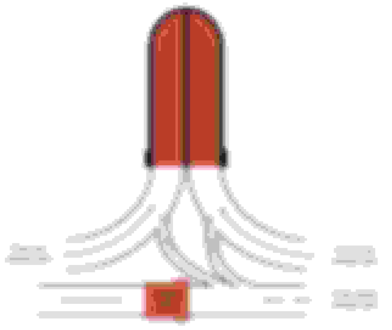
So the goal is to have minimal back-pressure in the primary at the time that the exhaust port opens on the next cycle.
Scenario 1: Siamese port rear half plumbs to rear primary and Siamese port front half plumbs to front primary (per diagram above). The pulse from the front ports through to the front turbine scroll pushes the turbine wheel faster, drawing more pressure from the rear primary away from the rear exhaust ports, making the backpressure of the rear primary quite low by the time the rear port opens on the next cycle. The pulses received by the front turbine scroll occur once every time the front exhaust ports open. Same applies to the rear.
Scenario 2: Siamese port rear half plumbs to front primary and Siamese port front half plumbs to rear primary. The front ports open,pressurizing the front primary, and partially pressurizing the rear primary. Half a cycle later, the rear ports open, and some exhaust flows through the rear primary into the front primary, which is still partially pressurized. Since the front primary is partially pressurized, this does not promote as much exhaust gas flow from the rear Siamese into the front primary. The pulses received by the front turbine scroll occur twice every time the front exhaust ports open - one (larger) pulse from the front port, and one (smaller) pulse from the rear Siamese port. I'm thinking that if this method were better we would have seen small breathers plumbed between front and rear primaries on REW manifolds to assist with some cross-flow of exhaust pulses between the scrolls as the gas flows from the exhaust ports towards the turbine housing.
Where are you going to find the room for all of that?
I also feel like the Siamese port divided like that will be an issue. just route it to join one of the outer ports only
Ya, it may not even physically be possible with a low mount setup, but I want to explore the design options before I start building. It helps that smaller pipe diameters can be used for each half of the Siamese,a s less flows out of these than out of the front and rear primaries. Also the WGs with proposed twin scroll design don't have to be located as close to the Siamese as I was previously expecting.
Brett got me thinking yesterday when he voiced a theory that there is excessive back-pressure at the Siamese port (before the waste gate) with the method you suggest - , and that excessive back-pressure is reducing the amount of exhaust gas expelled out of the Siamese port from the combustion chamber at higher power levels. Looking to identify the best current theoretical manifold design - it seems to be improving in iterations recently (credit to Brett for pushing the envelope).
So the goal is to have minimal back-pressure in the primary at the time that the exhaust port opens on the next cycle.
Scenario 1: Siamese port rear half plumbs to rear primary and Siamese port front half plumbs to front primary (per diagram above). The pulse from the front ports through to the front turbine scroll pushes the turbine wheel faster, drawing more pressure from the rear primary away from the rear exhaust ports, making the backpressure of the rear primary quite low by the time the rear port opens on the next cycle. The pulses received by the front turbine scroll occur once every time the front exhaust ports open. Same applies to the rear.
Scenario 2: Siamese port rear half plumbs to front primary and Siamese port front half plumbs to rear primary. The front ports open,pressurizing the front primary, and partially pressurizing the rear primary. Half a cycle later, the rear ports open, and some exhaust flows through the rear primary into the front primary, which is still partially pressurized. Since the front primary is partially pressurized, this does not promote as much exhaust gas flow from the rear Siamese into the front primary. The pulses received by the front turbine scroll occur twice every time the front exhaust ports open - one (larger) pulse from the front port, and one (smaller) pulse from the rear Siamese port. I'm thinking that if this method were better we would have seen small breathers plumbed between front and rear primaries on REW manifolds to assist with some cross-flow of exhaust pulses between the scrolls as the gas flows from the exhaust ports towards the turbine housing.
For the purposes of getting maximum benefit from a twin scroll you need to think about the engine as having 4 exhaust pulses - similar to a four cylinder engine . Twin scroll effectiveness is about separating those pulses as much as possible as the main energy from each pulse is in the first few milliseconds ... the remaining flow as the exhaust chamber gets evacuated does very little to accelerate the turbine .
Putting those pulses on top of eachother like in that diagram above is going to make the overall pulse energy lower ....IMO
Remember that I improved the spoolup on my setup by 800rpm when i had the engine rebuilt. Originally I thought that it was the improvement in compression that did most of that . Subsequent events have led me to believe that was only a small part of it . When we ported the engine , we ported the main exhaust ports only ,leaving the siamese stock . I'm pretty sure that doing this gave us the biggest improvement as now the main pulse is amplified, which suits my manifold design.
I hear what you're saying, but it makes me think that doing this (Scenario 2) would mean that the turbine wheel sees similar pulses on both sides of the scroll at the same time, which is very similar to what the wheel would see with a nice smooth equal runner single scroll design.
With Scenario 2, presumably two waste gates would still be required.
...there'd be a lot less fitment issues if I hard piped the coolant tubes out of the way for a top mount setup. Less vacuum on pre-turbo intake tube also, which is good for 1-2 extra PSI.
If I were starting over again ,with a low mount, I think the best result possible would be to divide the siamese all the way to a single wastegate with front and rear ports to the twin scroll.
The biggest challenge would then be whether the restricted siamese passage would allow enough flow to prevent boost creep at high power.
Apart from the obvious spoolup improvements the beauty of this design would be that pressure at the wastegate would be lower than that at the turbine . This would offer huge benefits for a bridgeported engine as the wastegate would scavange the last of the exhaust gases and pull the intake charge into the combustion chamber.
The effect would be akin to running a larger turbine without the downside of reduced spool .
Porting the end plates only and leaving the siamese stock would further improve spoolup.
EDIT : on reflection , this design is best ONLY if the porting work is done.
Have you had a heat related failure at the Siamese port? I'm a bit concerned about melting a divider if I put one in there. I'd make it part of the manifold, and the divider plate would extend into the port from the manifold flange. A small gap for heat expansion would be required.
I did have a divider fail but because it was loose . If you port the main ports you don't get a big pulse in the Siamese so that significantly reduces the chances . Also .......so what if it fails ? Turbo won't get the shrapnel.
Thanks for the input. Let's see how the above design goes on my motor and then we can figure out if it's any good. If it doesn't work well I can always take your brand off the above diagram - don't want to get done for defamation
Not planning on porting exhaust ports at the moment, but you never know what luck my motor will have in the next few months.
The more I review my past failures and successes the more convinced I become that the real problem here is the fact that the pulse strength is divided in two instead of being one solid pulse like in the pp engines. This added to the fact that the siamese port is a pulse killer by design makes a twin scroll turbo on a stock block of limited value.
That last design above is really not much different than my original design , which was a fail .By sealing off one side from the other there will be an improvement , but you still end up dividing the pulse into two , with the siamese pulse ending up dead headed.
The reason my current setup works well is due to the porting of the side exhaust . By increasing the pulse strength of one side , suddenly the twin scroll started to do it's thing. In my next engine we will attempt to improve this even more.
So unless you intend to also open up your engine and do some porting I think you're going to be disappointed with pretty much any design you can come up with.
So you're saying that a single scroll design (similar to rx8performance) will give similar results to a twin scroll with stock porting?
I was mocking up my new manifold this morning and concluding that I'd need to go top mount if I were to use the above design. No idea how your fabricator fit all that into a low mount position.
Yeah , I guess I am saying that ... heh .
Apart from the poor transitions for the end ports ... that rx8performance design is a really good one for a low mount with stock ports. I would change the position of the wastegate to take advantage of what we now know will work.
Do you remember the ebay manifold someone posted on my thread ?
But seeing as I already went down the twin scroll path (and am bloody minded) it makes sense for me to keep pursuing the concept after seeing big gains from what was some pretty minor porting work.
Gotcha. I didn't fully appreciate that design before discussing the benefit of centre port flow to WG. I'd smooth out the front runner into the turbine housing a bit more.
I have a slightly different set of clearance issues from you given my CHRA is a lot shorter than yours.
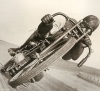
I'll need to pull the turbo off the car to make final fitment checks, but my current jig is good enough to mock up a suitable routing path for the runners. Pics below show what will not work - WG in the location below presents clearance issues with oil drain, motor mount bolts and WG vband clamp bolts, so it's a no-go.
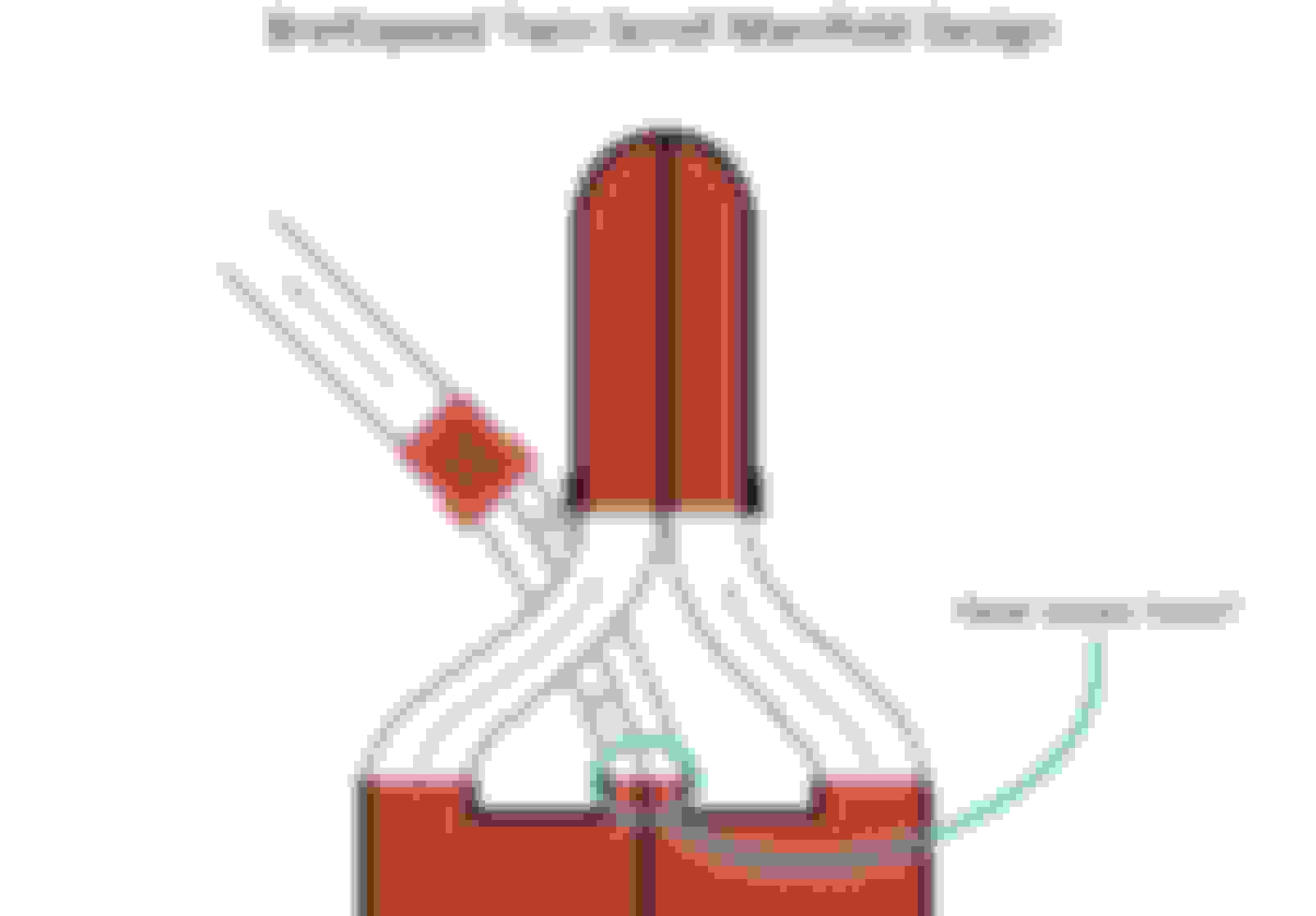
However, once I identified that there are serious issues with the above I had another chat with Brett and we've now come up with design concept in the diagram below - seems like we're going round in circles, but we're both happy with the latest design below, so that's what I'll be working towards. It's pretty much a mash up of Brett's own manifold design and the ebay manifold design (pics inset in diagram below). WG is now located further back where it's not fighting for space with oil drain, motor mount and cold side piping. It also allows for slightly smoother transitions of the runners.
However, once I identified that there are serious issues with the above I had another chat with Brett and we've now come up with design concept in the diagram below - seems like we're going round in circles, but we're both happy with the latest design below, so that's what I'll be working towards. It's pretty much a mash up of Brett's own manifold design and the ebay manifold design (pics inset in diagram below). WG is now located further back where it's not fighting for space with oil drain, motor mount and cold side piping. It also allows for slightly smoother transitions of the runners.
I'm happy that design will work when the side exhaust ports are ported and you have a joining pipe a little bigger than the area on one side of the siamese sleeve.
Unfortunately I would have to say it wont be any better spoolup(probably worse) than a properly done single scroll if the porting work isn't done.


 08-03-2016, 05:47 PM