When you click on links to various merchants on this site and make a purchase, this can result in this site earning a commission. Affiliate programs and affiliations include, but are not limited to, the eBay Partner Network.
I've been running this setup as a daily driver since it was installed in February 2015, with peak boost of 11.5psi. Zero issues to date (touch wood).
Preparation
I didn't want to chase my tail with issues after the turbo installation, so I installed as many items as I could while still NA. This let me identify and fix issues easily before they turned into big issues.
Parts Installed Before Turbo Conversion
Oil catch can plumbed to intake (not VTA)
MazdaEdit license and OBD2 adapter.
Prosport Premium Oil Temp Gauge. Beeps and flashes when the programmed max value is reached.
Prosport Premium Coolant Temp Gauge. Beeps and flashes when the programmed max value is reached.
Prosport Premium Fuel Pressure Gauge. Beeps and flashes when the programmed minimum value is reached.
Prosport Performance Boost Gauge.
Innovate AFR Gauge. MTX-L with LSU 4.9 sensor. Displays min AFR of 7.35 – required for tuning below OEM sensor minimum of 11.
Oil filter adaptor plate (M20x1.5 adapter) for oil temp gauge sensor and turbo oil feed.
Air pump delete.
BHR midpipe and high flow cat (installed 12 months prior).
BHR Coils and leads. Tune updated with new dwell times.
Replaced OEM plastic grill with metal mesh for improved airflow to intake, IC and radiator.
Deatschworks DW200 fuel pump. Part number 140115, flows 255lph.
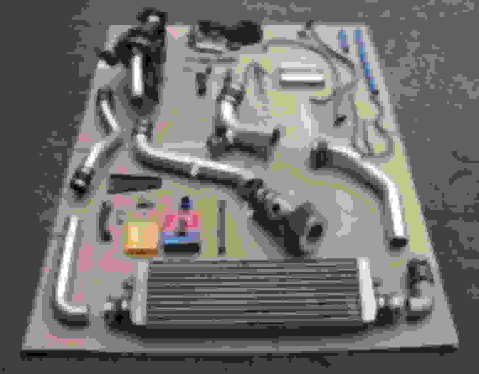
Parts Installed During Turbo Conversion
Greddy turbo (t618z/Mitsubishi TD06-18g) rebuilt and modified with larger anti-surge ported compressor housing and 53/71 (56trim) compressor wheel
Electronic Boost Controller – GFB G-Force2
Intercooler – dimensions 600x280x100mm
AEM MAF tube running forward through front firewall to stock Greddy air filter
BOV - HKS SSQV with 1.25” recirc adapter
Oil feed line – Oil filter adaptor plate to 1/8NTP adapter to -3AN line to 1mm oil restrictor to M10x1.25 adapter to turbo CHRA
Oil drain line – Stock Greddy oil drain pipe to -10AN hose to -10AN hose adapter to -10AN flange welded to stock oil pan, 5cm forward of oil drain plug.
Adhesive heat shield matting on underside of transmission tunnel above the turbo location
Exhaust wrap protecting compressor inlet pipe from exhaust manifold
Extreme ceramic coated Greddy exhaust manifold
Vacuum hose connections:
Post-MAF nipple 1 to check valve to jet air
Post-MAF nipple 2 to catch can to oil filler neck
Post-MAF nipple 3 to oil injection line as per stock
Wastegate to EBC
EBC to Turbo compressor housing nipple
Boost gauge sensor T’d with BOV signal to UIM.
Nipple near dipstick to be capped off.
Engine
The engine had a fresh rebuild with deep groove 2mm rx7 ALS apex seals, new housings and OEM everything else.
Turbo
I had the turbo rebuilt prior to install. When I picked up the rebuilt and balanced turbo I found a few issues …
A stock 12 fin turbine wheel was used instead of my requested 11 fin wheel.
A 56 trim compressor wheel was used instead of my requested 57-59 trim wheel. Hmmm, not quite the rebuild I was looking for but at least it’ll spool nicely.
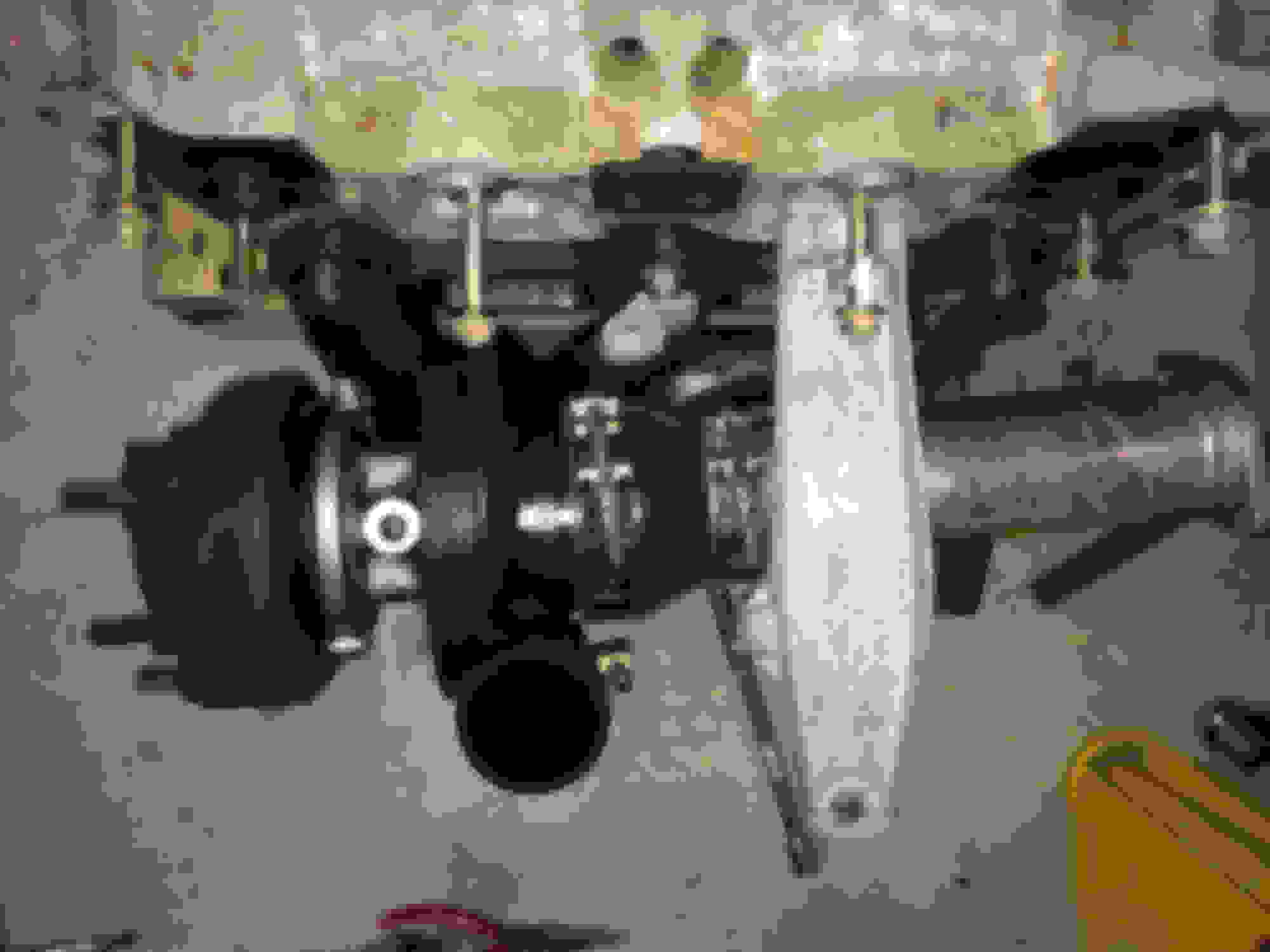
Original compressor housing was replaced with a slightly larger anti-surge housing, which he said should improve performance a little. Goodbye waste gate actuator mount. I got him to tap a new WG mount into the comp housing and add a nipple for WG actuator signal while he was at it. That just left me with the fact that the new larger compressor no longer cleared the exhaust manifold. No big deal, I sourced a 10mm T25 flange to space the turbo out from the manifold.
Above issues were due to my lack of experience at the time and some poor communication from the builder. You honestly don't know how ignorant you are until you learn some **** the hard way. With 20/20 hindsight I'd manage it differently in the future.
Tuning
Being a Kiwi it was only natural to get in contact with Brettus for some assistance with tuning. He’s a wealth of knowledge and was able to give recommendations on most aspects of the build. Props to the big man.
Boost Profile
To maximise performance and engine longevity I’m not planning to run more than 12psi. There’s a bit of head room here due to the solid tune. I’ve inadvertently over-boosted to 14psi a few times after wastegate/exhaust changes and didn’t notice any detonation.
Using only the mechanical waste gate actuator (EBC not programmed) peak boost is at about 4.5krpm in 3rd gear, and drops by about 3psi towards the top of the rpm range. The EBC is used to help the boost come in a sooner and minimise boost taper through the upper rpm range.
My long-term setup is using the EBC to hit peak boost of 11.7psi, dropping to 10.5 at peak rpm. If I turn off the EBC the mechanical actuator is set to a peak of 9.3psi, dropping to 6.5psi peak rpm. I’ve found that the actuator works best on this setting.
A few pics:
2005 6 port 6 speed with Greddy turbo installed.
Standard Greddy kit (not mine).
Trial fit of rebuilt turbo with larger compressor housing.
T25 flange spacer between manifold and turbine housing.
Looks good dude! What eyelids are those/where did you get them from and how was fitment? I ordered some and fitment was not great and the LY color is way off haha
Looks good dude! What eyelids are those/where did you get them from and how was fitment? I ordered some and fitment was not great and the LY color is way off haha
Those eyelids are cheap ebay ones, and to be honest I wouldn't recommend them. They don't look quite as good in the flesh as they do in pics. While the color is OK, fitment is not that great, and they're not as smooth/flat as I'd like. I'm considering ordering some more that have the curve around the side of the headlight closest to the grill. Vinyl wrap is another option. You'd probably want to go carbon or black as it'd be pretty difficult to color match the vinyl to the paintjob.
Nah, I just got my MS bumper painted.... and yes it was very difficult to match LY.... but I would be able to get the eyelids painted the same as the bumper. Same as you though, I don't want to put the effort in if they aren't going to look good in person.
Picked up these old school 18x9.5 rims. Put some sticky 245 tires on them and it's sorted out some of the traction issues.
Groovy - cut to take 2mm rx7 apex seals
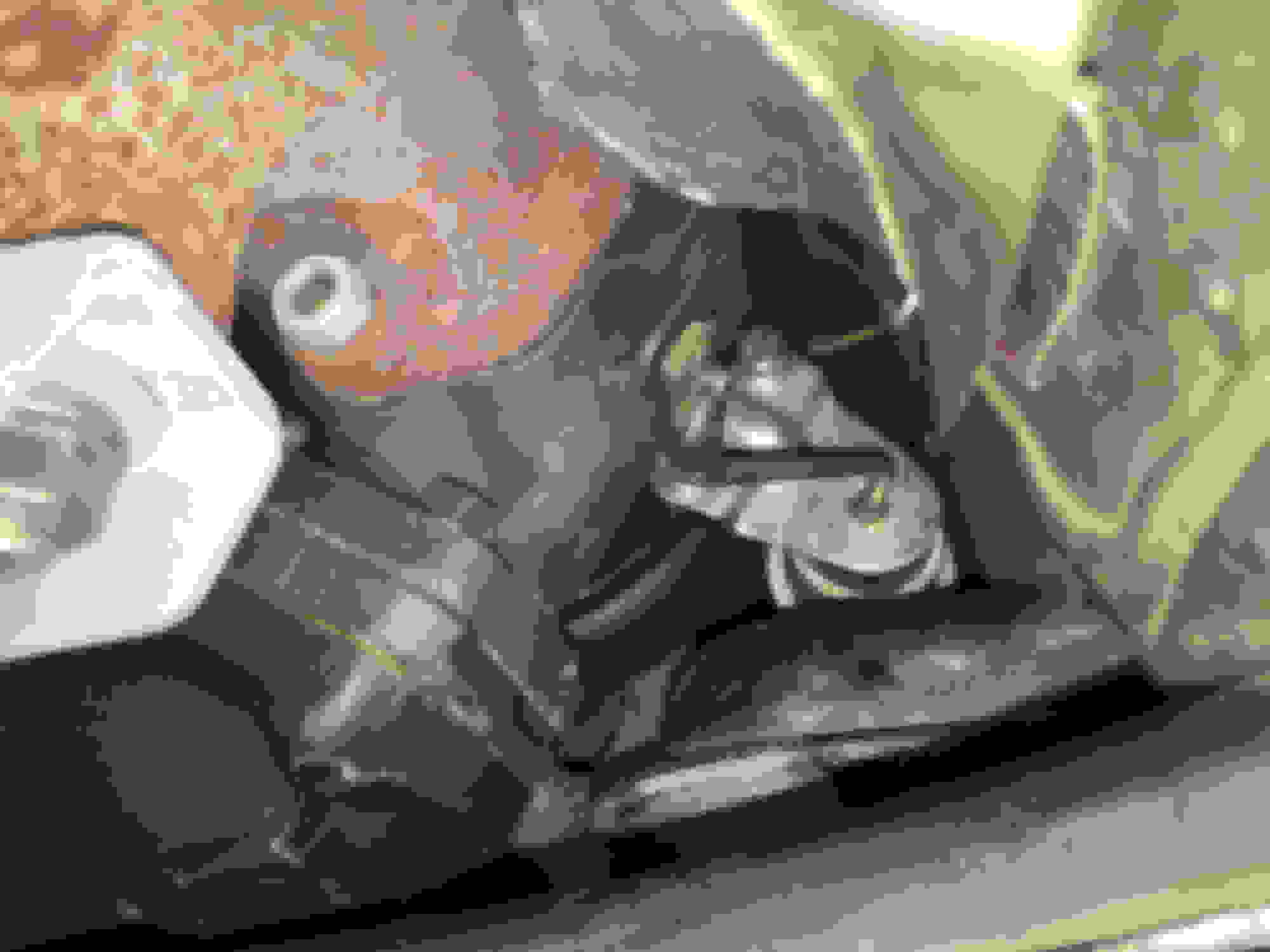
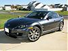
Looking upwards from the ground, shows oil drain location into sump. I wrapped the compressor inlet pipe and silicon reducer as it practically sits on the manifold with the larger compressor housing.
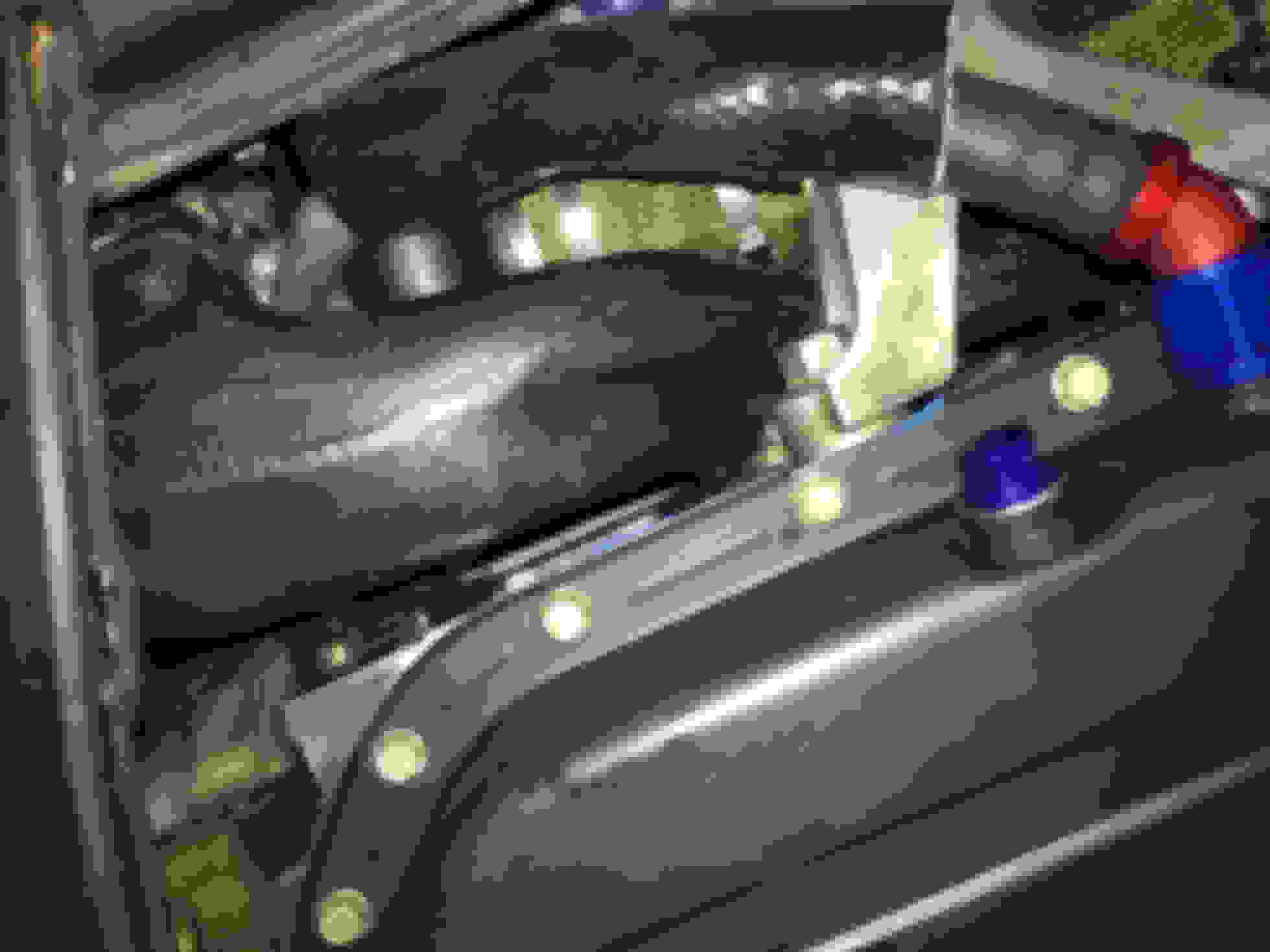
While doing homework for the build I was having trouble summarising all the different opinions on vac hose plumbing into one solution, so I drew a picture.
Too bad its not possible to put on more than one like on a post, I should have freaking wore out the button on my mouse...
One question, the line from compressor output, going to Boost solenoid, is that just a "supply" for operating valve? So that if say you have a pressure drop of 2psi in intercooler, compressor will be delivering 14psi to get 12psi after IC, because its really EBC that runs the show, and is sensing after IC?
Picked up these old school 18x9.5 rims. Put some sticky 245 tires on them and it's sorted out some of the traction issues.
While doing homework for the build I was having trouble summarising all the different opinions on vac hose plumbing into one solution, so I drew a picture.
Just curious why you put wider rims on the car but put the same width of tires as stock? Why not put a 255 or 265 tire on there? My bad... stock is 225!
Also nice diagram... Looks identical to mine except I have my EBC boost signal coming from Pre-TB (may want to look into this a bit more because I believe it is better off plumbing your EBC pre-TB as it will give you greater control over the turbo no matter what position your throttle plate is in). I tee'd my EBC signal line into my jet air hose just off the charge pipe post IC pre TB. I have a mechanical boost gauge measuring post TB getting it's signal from the same place you have your EBC boost signal plumbed to (where VFad used to be).
Originally Posted by AAaF
Too bad its not possible to put on more than one like on a post, I should have freaking wore out the button on my mouse...
One question, the line from compressor output, going to Boost solenoid, is that just a "supply" for operating valve? So that if say you have a pressure drop of 2psi in intercooler, compressor will be delivering 14psi to get 12psi after IC, because its really EBC that runs the show, and is sensing after IC?
The pressure coming off the compressor outlet is regulated by the boost control soleniod so that the wastegate diaphram only see's the amount of pressure you want it to see coming off the turbo. If you're trying to run 12psi on a 7psi spring/diaphram you don't want your wastegate pegging open before you ever hit the 12psi!
Last edited by RotaryMachineRx; Sep 9, 2015 at 09:28 AM.
Just curious why you put wider rims on the car but put the same width of tires as stock? Why not put a 255 or 265 tire on there? My bad... stock is 225!
I was on a bid of a budget for the tires so had to choose between cheap 275s or super-sticky 245s. I was told by the tire guy that the sticky 245s would give better over-all grip and will likely last longer, be quieter and have fewer fitment issues...but the 275s would have looked nice!
Originally Posted by RotaryMachineRx
Also nice diagram... Looks identical to mine except I have my EBC boost signal coming from Pre-TB (may want to look into this a bit more because I believe it is better off plumbing your EBC pre-TB as it will give you greater control over the turbo no matter what position your throttle plate is in). I tee'd my EBC signal line into my jet air hose just off the charge pipe post IC pre TB. I have a mechanical boost gauge measuring post TB getting it's signal from the same place you have your EBC boost signal plumbed to (where VFad used to be).
After doing some reading I plumbed the EBC signal lines the same as indicated in the installation guide. The line coming from the UIM to the EBC screen is only for display purposes, and is what we use to configure the settings that control the solenoid. This is a suitable location as it reads vacuum as well as boost so you can clearly see when the engine is under boost. The solenoid uses the values we set on the display unit to adjust the signal it's receiving from the compressor before sending on to the WG actuator. The take away point is that the solenoid should not receive it's signal from the intake manifold where the TB plate can get in the way of reading the actual boost the turbo is generating. In some partial throttle circumstances this can cause some nasty issues.
More details on this thread.
What I don't know is whether there is a real world benefit of having the solenoid input signal plumbed in close to the BOV at the pre-TB location as you suggest, or whether it's fine in it's current location on the compressor housing. I'd imagine it makes little difference to how the car drives - feels like a factory turbo charged car the way she currently drives.
^^ No I wasn't talking about the solenoid... maybe yours is different than the GReddy EBC but the solenoid is controlled by the EBC unit, which in your situation is getting it's boost reading from after the TB. What this means is that the EBC could be seeing a vacuum behind the throttle plate when really you could have 25psi (just a randomly selected number) built up between your turbo and throttle plate. The EBC would not see this pressure as it is plumbed in behind your throttle plate so it would maintain your solenoid in the closed position. This line (in the case of the Profec Bspec) is not just for a boost gauge but is also for your EBC to determine when/how to control the solenoid accordingly to your start boost, set pres, and gain settings. Long story short, under partial throttle your EBC does not have total control over your turbo because it is not getting a consistent boost signal due to the throttle plate. It shouldn't matter to your EBC if you are in vacuum. Your separate boost gauge should be plumbed into the intake manifold to show you whether you are in boost or vacuum.
It's the same as when guys run no EBC and they just plumb the WG actuator to the charge piping. The GReddy instructions call for the wastegate to be plumbed to the LIM which we know is not a great idea as it F's with your throttle control because you can have sitiations where there is a lot of built up boost pressure in front of the throttle plate (ie partial throttle) causing boost spikes, etc.
I see your comment about how the car drives like a factory turbo charged car so don't think I'm hating on you or anything, just trying to pass along some information that has been learned along the way.
Last edited by RotaryMachineRx; Sep 9, 2015 at 07:19 PM.
What I don't know is whether there is a real world benefit of having the solenoid input signal plumbed in close to the BOV at the pre-TB location as you suggest, or whether it's fine in it's current location on the compressor housing. I'd imagine it makes little difference to how the car drives - feels like a factory turbo charged car the way she currently drives.
Don't think of the soleniod as receiving a "signal" from the turbo outlet. The solenoid (again I am referring to the GReddy) is controlled electronically by the EBC head unit, which gets its data from the boost signal line (the one you have plumbed into your UIM). The solenoid itself is just a gate which regulates how much pressure is getting from the turbo outlet to the wastegate actuator. There would be no effect moving the solenoid input closer to the TB from your compressor outlet unless you are running with the EBC off (ie solenoid fail open).
Last edited by RotaryMachineRx; Sep 9, 2015 at 07:16 PM.
...so don't think I'm hating on you or anything, just trying to pass along some information that has been learned along the way.
It's all good - gotta discuss to understand.
So a standard WG (and MBC) signal should feed from pre-TB, not UIM.
Pretty sure my EBC works correctly with signal feed from the UIM, but since I've got a spare boost gauge already installed, I'll hook it up pre-TB so I can confirm that I'm not getting big boost at part throttle. Like you say, the source of the EBC signal could vary depending on brand of EBC, so best to check the user guide. Does your Profec gives you dramas if you hook it up to the UIM? I had a quick look at the Profec manual and the diagram had no TB. Must have been a diesel lol
There's a really good short explanation of how the EBC controls the solenoid on page 16 of my EBC manual here. Explains pretty clearly how the solenoid works based on % of the time it's open rather than on a fixed psi value read by the EBC. In theory it doesn't matter what the EBC signal is at, if the boost pressure at the compressor gets too high it'll just let a portion of that through which will open up the WG to control the boost level.
Using only the mechanical waste gate actuator (EBC not programmed) peak boost is at about 4.5krpm in 3rd gear, and drops by about 3psi towards the top of the rpm range. The EBC is used to help the boost come in a sooner and minimise boost taper through the upper rpm range.
My long-term setup is using the EBC to hit peak boost of 11.7psi, dropping to 10.5 at peak rpm. If I turn off the EBC the mechanical actuator is set to a peak of 9.3psi, dropping to 6.5psi peak rpm. I’ve found that the actuator works best on this setting.
Is this still true, you are just running with the EBC turned off right now?
Originally Posted by JimmyBlack
It's all good - gotta discuss to understand.
So a standard WG (and MBC) signal should feed from pre-TB, not UIM. YES 100%!!!!!
Pretty sure my EBC works correctly with signal feed from the UIM, but since I've got a spare boost gauge already installed, I'll hook it up pre-TB so I can confirm that I'm not getting big boost at part throttle. Like you say, the source of the EBC signal could vary depending on brand of EBC, so best to check the user guide. Does your Profec gives you dramas if you hook it up to the UIM? I had a quick look at the Profec manual and the diagram had no TB. Must have been a diesel lol
There's a really good short explanation of how the EBC controls the solenoid on page 16 of my EBC manual here. Explains pretty clearly how the solenoid works based on % of the time it's open rather than on a fixed psi value read by the EBC. In theory it doesn't matter what the EBC signal is at, if the boost pressure at the compressor gets too high it'll just let a portion of that through which will open up the WG to control the boost level.
Yes a standard wastegate actuator with no boost controller should get its signal from pre TB.... It is one of the 3 GReddy fixes and is the origin of why you see everyone get a nipple installed on their GReddy turbo outlets (I recommend searching for the GReddy fixes thread if you haven't done so already).
I'm going to go off on a bit of a theoretical tangent here so bear with me! Haha
First off I don't have time right at the moment to have a look at ur EBC manual (I will have a look in the morning) but judging by the diagram it operates exactly like a GReddy EBC. So unless the solenoid has some type of pressure sensor in it that can measure the pressure at the turbo outlet (which I am very doubtful of); it is just a mechanical valve that is controlled by the EBC head unit. So the fact that the signal source post TB messing with it is not a matter of brand, it is just purely physics. With the throttle body barely open but say going up a large hill you are going to have a larger load meaning more exhaust gas meaning more spool meaning bigger pressure in your charge piping pre-TB. Let's say for example 25psi. But since your TB is only opened partially, let's say 25% (again just throwing a number out there), you are going to have a massive pressure drop across the TB, meaning 25psi upstream of TB but maybe only like 6psi downstream of the TB. So if you are trying to push 12psi out of your turbo but post TB where your EBC source signal is coming from is measuring only 6psi; The EBC thinks hey, I'm not at 12psi yet so I had better keep the solenoid closed until I see 12 psi. Well as you can imagine 25psi is well above the turbo efficiency range of the GReddy turbo meaning that air coming out of there is extremely hot. Not only is that dangerous for pre-ignition/detonation, but think of having a 19psi pressure differential across a partially open TB. Not only is that pressure against the butterfly valve that is your TB going to make it hard to really control the airflow with any finess but when you do decide to go from this high load, part throttle situation to wide open throttle all of a sudden BAM! You have a huge spike of 25 psi trying to slam through that manifold and into the engine. Then your EBC signal source is going to pick up this huge pressure spike and is going to cause your solenoid to go from 1 second held closed, to the next second madly trying to vent exhaust gas through your wastegate which in turn means your turbo is going from spinning at this MASSIVE rpm that was producing hot *** 25psi air down to its normal operating range(and temperature) that produces 12psi in fractions of a second, which you can imagine is a bit rough of the lil guy. Not only is that mad fluctuations in rpm (turbos spin in the hundreds of thousands of RPMs) but that is also a lot of thermal stress on the turbo and everything around it.
Anyways, I hope that makes some sense..... It's late here, I hope it makes sense to me tomorrow when I read it over again
I'll get back to you on this after I've tested with the 2nd boost gauge pre-TB
I understand what you're saying, but I believe the EBC controls the solenoid slightly differently from the way you describe, meaning it can be run from the UIM without any risk of over-spooling. You gotta check the EBC manual I linked above, it'll explain how the solenoid is pre-programmed with these values so that it always acts the same way, leaking the compressor signal to the WG accordingly. I.e. it does not work primarily off of live instructions it's receiving from the EBC many times per second.
To answer your question, I've always been running the EBC per the diagram even when I had the values set to 0 so I could determine the current WG setting. At this point the comp pressure was passing unaltered through the solenoid to the WG. I then increased the values gradually over multiple pulls until I got the boost profile I wanted based on the Duty Cycle, Gain and Sensitivity parameters. Duty Cycle sets max boost, Gain determines how fast the boost is allowed to come on (independently of the EBC signal) and Sensitivity sets how quickly the boost is allowed to drop off after it reaches it's maximum value (the value is based on max value recorded during setting Duty Cycle).
Pulled this from the EBC manual:
The controller NEEDS to know this relationship between duty cycle and resulting boost pressure, because when
boost is rising quickly, it must pulse the solenoid at the correct duty cycle BEFORE the boost reaches the target
boost pressure. If it doesn’t know the correct duty cycle, it cannot do this.
After reading the manual I believe your EBC is nearly identical to the GReddy EBC.
Thanks for the link. I've read it before but completely forgot about it. Let's continue this EBC discussion on that thread. I'm now convinced to test pre-TB vs. post-TB EBC signal source, regardless of what I think the result will be I'll do the test in another week as I've got a few things I need to address first.
In other news, last weekend I finally fitted a 2nd oil cooler and AN lines. Most models of rx8 in New Zealand come with a single oil cooler - must be the colder climate. I was finding that travelling up long hills at around 15mph I was getting high oil temps.
Racing Beat oil line instructions were useful here.
It's winter time here, so I won't really get a chance to test the new cooling setup until I go to the track or wait until summer time. I've observed that the oil takes about 3 minutes longer to come up to temperature, and sits at a very constant 80C (176F), where it previously sat at about 86C. I've left the thermostats in both oil coolers. I didn't want to run the risk of cooling the oil too much on colder days.
In order to remove the factory hard oil line I had to remove the UIM, intake piping, coils and AC compressor. Took a bit longer than expected - ended up working from home for 2 days as the car was apart.
Shopping List:
5m of -10AN line
6x M18x1.5 to -10AN adapters
4x -10AN 90 degrees swivel host adapters
2x -10AN 45 degrees swivel host adapters
The 45 degree adapters bolt into the engine block. The 90 degree adapters bolt into the coolers. Oil line routing went from front of engine block to left side of left cooler, right side (inboard) of left cooler to left side (inboard) of right cooler, right side of right cooler to rear of engine block. The last run to the back of the block does not follow the path of the hard line along the top of the block underneath the coil plate and down under the AC compressor. Instead, it routes away from the block immediately towards the side of the car, and runs forward from there. It's easier to access here and doesn't move about or catch on any other components.
Thanks for the link. I've read it before but completely forgot about it. Let's continue this EBC discussion on that thread. I'm now convinced to test pre-TB vs. post-TB EBC signal source, regardless of what I think the result will be I'll do the test in another week as I've got a few things I need to address first.
So the things that need addressing are:
I'm running rich (low 10s) under boost since putting the UIM back on after the oil cooler install. Can't find any obvious vac leaks from visual inspection, but will have a thorough check tomorrow. MAF location hasn't changed, though the pipe was re-installed earlier this week, so may be a contributor.
I've ordered a K&N pod filter that fits correctly, to be fitted next week.
Fabrication of my custom exhaust has started. Deets and pics next week when it's fitted.
If I can't get my AFRs sorted I may need to beer up for another tune. Will wait till all is done next week though.
^ Gear up to search for a boost leak rather than a vac leak! Check all the couplers from the charge pipe you removed first, then I hate to say it.... But then go straight to the UIM. You definitely aren't the first person to report leaks after removing the UIM.
Last edited by RotaryMachineRx; Sep 10, 2015 at 09:34 PM.