
Need GReddy Profec B Spec-II help


it would have been simple to check if the actuator was to tight. take the c-clip of, pull the screw rod off the wastegate arm and see how far back it releases to its no tension position.

Thread Starter
Life begins @ 30 psi
Joined: Mar 2008
Posts: 1,745
Likes: 0
From: Columbia, MD
That just wasn't possible from where I was... it shouldn't be a problem if I get it up on a lift where I can actually reach the thing.
I did my whole turbo install on jackstands LOL, it's not impossible. Just pull the big *** bolt, then the two smaller bolts of the front cross member, then the two smaller ones on the driver sides, and just loosen the big one and swing it out of the way...
I hear ya on jack situation. I can't even get the factory scissor jack under my side skirts...in order to jack up the front end of my car I have to jack up under the diff, place a jackstand under the rear, drop it, THEN jack up the front and put a jackstand under it. I HATE it when I have to jack up my car, that's why I am looking at getting THIS once I have the money saved up, haha
I hear ya on jack situation. I can't even get the factory scissor jack under my side skirts...in order to jack up the front end of my car I have to jack up under the diff, place a jackstand under the rear, drop it, THEN jack up the front and put a jackstand under it. I HATE it when I have to jack up my car, that's why I am looking at getting THIS once I have the money saved up, haha
Thread Starter
Life begins @ 30 psi
Joined: Mar 2008
Posts: 1,745
Likes: 0
From: Columbia, MD
You have my absolute pity for doing the install on jackstands chicken, thats horrible. The clearance down there is just miserable. I could have reached the actuator today if I swung the cross member out of my way, but I was running really tight on time and knew I wouldn't be able to monkey with it for much more. That toy from Summit is beautiful though, I wouldn't mind one myself.  Then again, I wouldn't mind a garage for that matter.
Then again, I wouldn't mind a garage for that matter.
Thread Starter
Life begins @ 30 psi
Joined: Mar 2008
Posts: 1,745
Likes: 0
From: Columbia, MD
Alright, well... I am back in town and I've done a fair bit more work on trying to get this thing fixed. I got the car up on a lift today and examined the actuator and wastegate more closely. The actuator is moving and has tons of clearance space. I disconnected the pin and checked the travel on the wastegate itself and the actuator individually... both of them seemed largely fine. The actuator rod was actually a bit long, it looked like the wastegate was not fully closed at rest, so I tightened it 1.5 turns and reattached it. I used a vacuum pump to push air into the actuator nipple and the wastegate swung open fine.
I took the car on the road with the EBC turned off, but I was still seeing higher than expected boost pressures. Looks like my initial guess on the problem was wrong. For my next step I'm going to disconnect the EBC completely and try to get the car to behave with just the stock wastegate. Before I do this though I want to get some opinions on the way I have the vacuum lines set up now. When I originally installed the gauge cluster with Im_DANOMite we ran the vacuum line for the boost gauge to the lower intake manifold. There is a nipple on the side near the stock windshield wiper fluid reservoir that we used. It produced a strong and steady vacuum signal so I left it that way when the turbo was installed. PF Supercars installed the boost controller and BOV routing them to the VFAD nipple.
Just to make sure you have a visual of how things are connected, I got all Professor MSPaint and have an example of how things are set up now, and then what I propose to do to test the actuator. Let me know if this is doomed to failure, or if the locations I have these vacuum hoses wired to are just all around bad to begin with.
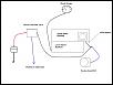
The first diagram is how I have things set up now. The boost controller valve has a vacuum signal from the VFAD, an output line to the intake tube, and a line to the actuator. The boost gauge is the only thing plumbed to the LIM right now with the BOV getting vacuum from a T-connector off the VFAD. It is also recirced back into the pipes.
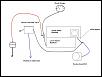
The second diagram is what I propose to remove the boost controller from the loop without disconnecting a ton of lines. Basically I want to leave all of the EBC vacuum lines right where they are, but removing the line from the valve to the actuator and capping it off. Then I would take the actuator line and run it to a T-connector into the LIM nipple where the boost gauge is getting its signal. That does several things for me... it puts the gauge and the actuator on the exact same vacuum source, it removes the EBC valve from the picture, and it keeps the whole system intact if the problem ends up being the actuator and not the valve or some other part of the EBC setup.
Is this reasonable?
I took the car on the road with the EBC turned off, but I was still seeing higher than expected boost pressures. Looks like my initial guess on the problem was wrong. For my next step I'm going to disconnect the EBC completely and try to get the car to behave with just the stock wastegate. Before I do this though I want to get some opinions on the way I have the vacuum lines set up now. When I originally installed the gauge cluster with Im_DANOMite we ran the vacuum line for the boost gauge to the lower intake manifold. There is a nipple on the side near the stock windshield wiper fluid reservoir that we used. It produced a strong and steady vacuum signal so I left it that way when the turbo was installed. PF Supercars installed the boost controller and BOV routing them to the VFAD nipple.
Just to make sure you have a visual of how things are connected, I got all Professor MSPaint and have an example of how things are set up now, and then what I propose to do to test the actuator. Let me know if this is doomed to failure, or if the locations I have these vacuum hoses wired to are just all around bad to begin with.
The first diagram is how I have things set up now. The boost controller valve has a vacuum signal from the VFAD, an output line to the intake tube, and a line to the actuator. The boost gauge is the only thing plumbed to the LIM right now with the BOV getting vacuum from a T-connector off the VFAD. It is also recirced back into the pipes.
The second diagram is what I propose to remove the boost controller from the loop without disconnecting a ton of lines. Basically I want to leave all of the EBC vacuum lines right where they are, but removing the line from the valve to the actuator and capping it off. Then I would take the actuator line and run it to a T-connector into the LIM nipple where the boost gauge is getting its signal. That does several things for me... it puts the gauge and the actuator on the exact same vacuum source, it removes the EBC valve from the picture, and it keeps the whole system intact if the problem ends up being the actuator and not the valve or some other part of the EBC setup.
Is this reasonable?
You're wastegate is setup incorrectly.
Since you have the GT3071R there should be a threaded nipple right off the turbo's compressor discharge. That goes to your w/g actuator with the boost controller solenoid plumbed in-between that hose.
Everything else should be hooked up to the VFAD nipple- BOV, Boost gauge, EBC signal. This is probably why you are overboosting.
Thread Starter
Life begins @ 30 psi
Joined: Mar 2008
Posts: 1,745
Likes: 0
From: Columbia, MD
Ahhhh, there is a vacuum source on the turbo compressor for the w/g actuator? Hmmm, how hard is that going to be to reach? So the EBC valve vacuum line that is currently going to the w/g actuator needs to go to a T-connector in between the compressor and the actuator?
im acutally in the process of trying to setup my boost controller settings now too..i started off with 2.5 psi..now im at currently at 7 psi then falling off to 5psi pretty quickly ***i noticed theres a difference between my ebc signal and my prosport gauge, roughly 1-2 psi and they are both plumbed to the vfad source***
Thread Starter
Life begins @ 30 psi
Joined: Mar 2008
Posts: 1,745
Likes: 0
From: Columbia, MD
Ahhhh, there is a vacuum source on the turbo compressor for the w/g actuator? Hmmm, how hard is that going to be to reach? So the EBC valve vacuum line that is currently going to the w/g actuator needs to go to a T-connector in between the compressor and the actuator?
I'm just worried about this being something I can even reach without yanking the damn turbo out. It sure doesn't sound like it...

Thread Starter
Life begins @ 30 psi
Joined: Mar 2008
Posts: 1,745
Likes: 0
From: Columbia, MD
Ok, thats not a problem, I have intermittent access to a garage with a lift... so I can remove that wheel pretty easily. Anybody have a picture of the 3071R where the vacuum nipple is that I'm supposed to have a line to? I wonder how PFS blocked it off.
I've got plenty of extra vacuum lines, so I can take a single piece of line, cut it in half, attach them with a T-connector and run one end from the actuator to the vacuum nipple by the compressor. Then I can take the line currently connected to the actuator (running to the EBC solenoid valve) to the T-connector.
Is there a reason why I should not have my boost controller unit and the boost gauge plumbed in to the lower intake manifold? That is where they are both going right now and the vacuum signal seems strong and reliable. Everything else goes to VFAD but I wanted to avoid a nest of T-connectors and vacuum lines run halfway across the engine if possible.

Registered
Joined: Apr 2005
Posts: 654
Likes: 4
Is there a reason why I should not have my boost controller unit and the boost gauge plumbed in to the lower intake manifold? That is where they are both going right now and the vacuum signal seems strong and reliable. Everything else goes to VFAD but I wanted to avoid a nest of T-connectors and vacuum lines run halfway across the engine if possible.
Now here's how the pressure source location works with an internal wastegate actuator.
The more pressure applied to the actuator, the sooner it will open up. Remember though that there are pressure drops across the intercooler and the rest of the plumbing. If you measured boost pressure in the compressor housing and boost pressure in the LIM at any given time, it would be lower in the LIM. With less pressure being applied to the actuator it will reduce its response. Although there may be times when tapping an intake manifold is appropriate, for an internally wastegated setup with boost control issues your plumbing is not a good idea.
What you should do now is run a line from the compressor outlet or pre FMIC intercooler piping directly to the wastegate. Leave the solenoid out. If the boost still creeps, you may be outflowing your wastegate. That's a very common problem on a rotary with an open exhaust.
Last edited by arghx7; Oct 20, 2009 at 06:57 PM.
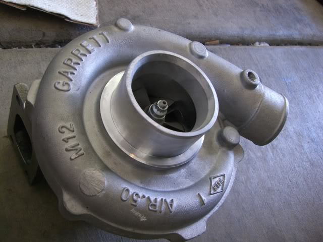
Here is where the threaded nipple should be- it's cast into the compressor discharge (gold barb at top of picture):
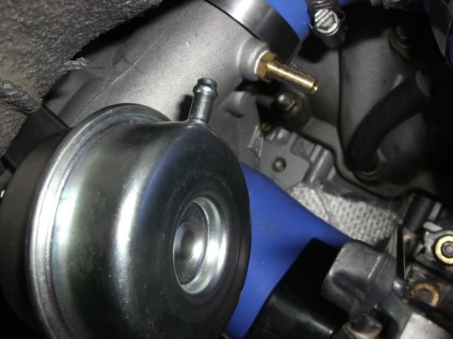
another angle, the barb isn't threaded in but you can see the hole right near the compressor discharge outlet:
Just run a length of vacuum hose from the w/g actuator to your boost control solenoid, then back down to the barb off the turbo. You're just putting the boost controller solenoid in-between signal and actuator, this is how the ebc modifies w/g signal.
Last edited by chickenwafer; Oct 20, 2009 at 07:13 PM.

The first diagram is how I have things set up now. The boost controller valve has a vacuum signal from the VFAD, an output line to the intake tube, and a line to the actuator. The boost gauge is the only thing plumbed to the LIM right now with the BOV getting vacuum from a T-connector off the VFAD. It is also recirced back into the pipes.
Attachment 147170
Attachment 147170
I assume you are talking about the boost solenoid valve here (not the profec controller itself)- mine has only two lines going to it . One from a pressure source BEFORE the throttle plate and one going to the wastegate actuator .
Your pressure source for the solenoid should NOT be coming from after the throttle plate .
Edit - do it like chicken mentions above ....
Registered
Joined: Apr 2005
Posts: 654
Likes: 4
I assume you are talking about the boost solenoid valve here (not the profec controller itself)- mine has only two lines going to it .
These diagrams from the Perrin boost control solenoid explains what I'm talking about, it's the same plumbing.


and here's an in-depth article on the plumbing side of boost control: http://www.perrinperformance.com/pages/show/113
but my main point is that he hooked into the UIM for his pressure source for the solenoid . This would create all sorts of boost control issues - especially at part throttle .
FWIW - Similar issues can occur (in some setups ) when you take the signal for the EBC from the UIM . But that is another argument discussed in some detail elsewhere ......
Last edited by Brettus; Oct 20, 2009 at 08:26 PM.
Thread Starter
Life begins @ 30 psi
Joined: Mar 2008
Posts: 1,745
Likes: 0
From: Columbia, MD
Alright, I think I've figured this out. First off, I apologize for being a dumbass. I really should have researched this more before asking for help with this, because I would have found the problem more quickly if I had really known what I was looking for. I made some assumptions about how they set up the boost controller, and when I traced the lines I was in a rush. When PF Supercars installed it they ran one of the lines from the VFAD around the engine bay and under the lining on the left side of the car under where the EBC valve was mounted so it looked like it ran into the bottom of the valve. When I looked at it more closely today I saw it wasn't actually connected to it.
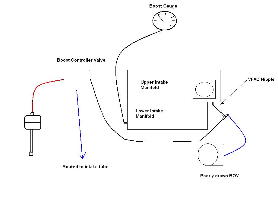
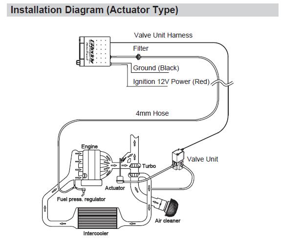
The way the GReddy manual says to install it is like this diagram:
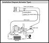
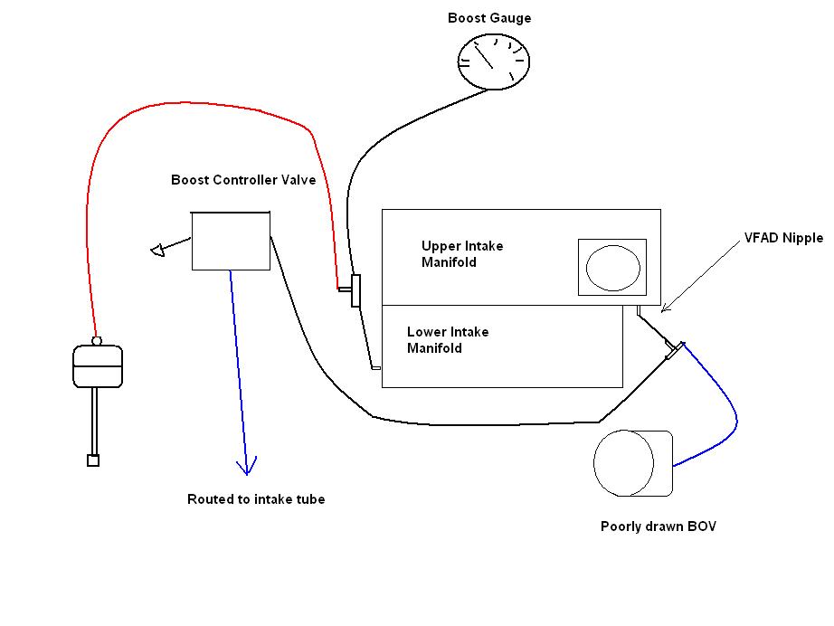
The way things are currently set up is ACTUALLY like this:
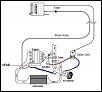
So the line from the NO port is supposed to go to the turbo compressor housing and instead is going to one of the empty nipples on the AEM intake pipe. Correct me if I'm wrong, but the intake pipe is before the throttle body and is not a good source for vacuum for the valve unit. If I disconnect this line and run it to the compressor housing and block off the nipple on the intake pipe it should be configured properly. The only thing plumbed to the LIM is the boost gauge, everything else is connected to the VFAD.
The way the GReddy manual says to install it is like this diagram:
The way things are currently set up is ACTUALLY like this:
- Main unit runs a line to T-connector at VFAD passing through supplied air filter
- BOV runs to T-connector at VFAD
- Boost gauge runs to LIM
- Valve unit has one line from the COM port directly to actuator, another from the NO port to the intake tube
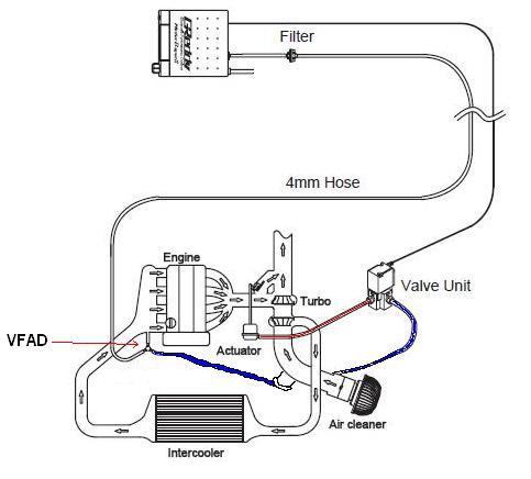
So the line from the NO port is supposed to go to the turbo compressor housing and instead is going to one of the empty nipples on the AEM intake pipe. Correct me if I'm wrong, but the intake pipe is before the throttle body and is not a good source for vacuum for the valve unit. If I disconnect this line and run it to the compressor housing and block off the nipple on the intake pipe it should be configured properly. The only thing plumbed to the LIM is the boost gauge, everything else is connected to the VFAD.
Registered
Joined: Apr 2005
Posts: 654
Likes: 4
Are you SURE that's how it's hooked up? that's a major gaffe, you could've blown a motor that way. Anything hooked to the turbo inlet pipe will not see boost.
Hook the NO port to the compressor housing. Either vent the NC port or run it to that same intake nipple.
Thread Starter
Life begins @ 30 psi
Joined: Mar 2008
Posts: 1,745
Likes: 0
From: Columbia, MD
Yeah, its definitely how its hooked up... I wasn't concerned when I first saw it because I thought it was a third vacuum line to vent excess from the valve... nope. I'll take a picture of it before I change it (charging camera). It certainly explains why I was seeing absolutely NO falloff of boost. It was acting like the wastegate was staying completely closed ....which it was. I'm going to swap the line to the proper location tomorrow.
this is the way you should hook it up dont use the second picture.. the first one is the way to hook it up..the first picture where it shows fuel pressure regulator that is your vfad source..**the second picture looks like the boost controller signal **the vacuum line that connects to the back of the boost controller is plummed into the intake which will not see boost levels...
Thread Starter
Life begins @ 30 psi
Joined: Mar 2008
Posts: 1,745
Likes: 0
From: Columbia, MD
Right gregs, I just figured that out today that the line going to the intake was not an output line but the NO port and would never see pressure. It explained all my problems immediately. 5000+ miles with no wastegate! Woo. Thanks PF Supercars.
Holy **** that is an epic fail. How the hell can a shop mess it up that bad??
So what did PFS do with the nipple off the turbos compressor housing? Is it just left open? If so you have a good boost leak going.
So what did PFS do with the nipple off the turbos compressor housing? Is it just left open? If so you have a good boost leak going.