When you click on links to various merchants on this site and make a purchase, this can result in this site earning a commission. Affiliate programs and affiliations include, but are not limited to, the eBay Partner Network.
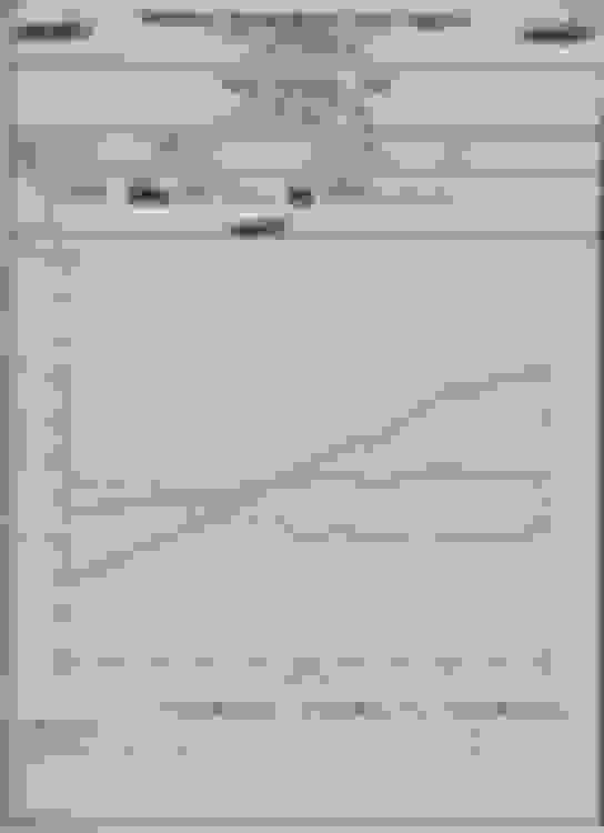
I never saw any dyno results with that oscillating wave pattern before, but the the Israeli military asked me to check and see if they can do a physical evaluation of your head? They see some potential to update their tank armor if that kind of resistance against penetration can be duplicated.
Funny
I know you have trouble looking at charts Team but just have another look here and try imagining the red line isn't there and just look at the blue line . You can do eet !
Yeah, I see the blue torque line oscillating like the Pacific Ocean and the corresponding HP curve. How come you can’t see that and don’t recognize it as not being typical?
Maybe you need a more direct comparison, here you go:
It's probably because you are not used to seeing the readout from a hub dyno . I am, and can tell you the blue line is normal for an rx8 on this style of dyno.
I've personally seen rx8s dynoed on 6 different dynos in and around my town .
*Mainline
*Torque performance x2
*Dyno dynamics
*couple of others I can't remember the brand
The chart looks different in subtle ways on all of them ....none look like the mustang one you put up or the typical dynojet ones you get over there . Who's to say which is................................. 'right' ?
Your dyno chart is under the "cloud of impeachment". I can see this debate going on for years into the future, especially if your new ideas put down some performance.
I feel for you...
Maybe we can crowdfund a fresh run for you, so we can all move forward, and you can continue the work of the people. I will be happy to donate. We all need to "move on".
Thanks Kevin . I think i'll give up on the idea that the original engine can provide a good baseline anyway. As soon as I saw the very first run make over 210whp I knew I'd be pushing **** up hill on this whole exercise. It has obviously had some work done to it so it was never going to provide a good comparison to a stock Renesis.
Once I've fitted the new engine and road tested it ...I will know myself whether it's making good power. If so it will be worth taking around to 2-3 dynos that I've used in the past.
There’s no impeachment. As you stated again, the numbers didn’t add up initially. Then further, to me the subsequent graph also seems suspect. Maybe try to remember that since some of my ideas are involved that there’s a bit of vested interest in the results for me too. Frankly it’s rather frustrating, but I’ll just leave it at that.
.
Maybe try to remember that since some of my ideas are involved that there�s a bit of vested interest in the results for me too. Frankly it�s rather frustrating, but I�ll just leave it at that.
.
At this point I don't see any test I can do that proves anything ... Doing another pull on a different dyno would maybe give us a curve that looks more like we are used to seeing ......... so what though ? It's still an engine with unknown porting in there.
The opportunity to prove anything with your manifold design has passed ... I did my best to get a meaningful result there and we couldn't find one after maybe a dozen 'before' and a dozen 'after' pulls. A more conclusive test may have been a stock mani. with a 3" system vs your manifold and a 3" system . But to do that I needed a 3" system .
If my result was poor I may have bothered to fit one ...but it wasn't poor ...it was great!
Just looking at the way the paint has discolored on the runners made me realise ...... A better design would have been to bring the runners out at the same angle as the exhaust port runner ! It's obvious exhaust gas is hitting the bottom of the outlet runner which will be bad for flow potential.
If anything it doesn’t look like the main outlet cone is angled far enough downward for the two rear ports to come in fully at the top of it like I did it. You can do that with two more elbows, but imo it’s not going to improve flow. You have to understand that as originally designed by me that that the siamese and rear port is directed into the curve of the cone rather than just dumping in the middle with the front port pushing it, resulting in it spiraling out. The rear port is coming out at the 3” outlet joint. You’re back into the tuned header thought process imo. There’s no resonance tuning with zero overlap. None. It just has to get out of the rotor chamber with as minimum backpressure as possible. That’s the end of it.
Sounds like you didn't get what I was talking about . I mean the angle of the port runner inside the engine is about 15-20 degrees ...see pic below. If the manifold inlets were on the same angle , the exhaust gas wouldn't hit the sidewalls as it made it's way to the cone .
Sounds like you didn't get what I was talking about . I mean the angle of the port runner inside the engine is about 15-20 degrees ...see pic below. If the manifold inlets were on the same angle , the exhaust gas wouldn't hit the sidewalls as it made it's way to the cone .
You�re probably taking a little pressure loss due to that turn as it enters the manifold...probably getting some recirculation at the top if the runner. I think you could probably further reduce losses if the Siamese port and the rear port could be turned to the back some before entering the main log...though you probably run into space limitations try to execute that.
Imo you’re way overthinking it. Those ports are huge for the amount of exhaust gas going through them. Think about this too, because a lot of people don’t wrt the Renesis; the exhaust port is not “suddenly” open. The rotor is sliding by and opening (and closing) like a slide gate. Based on your own thought process, it’s already hitting the port wall from the rotor housing into the port itself. There’s no smooth exhaust flow going on in there. It’s entirely turbulent through the basic design of how the port opens and exhaust gases flow through. Which again, you’re only goal here is to make it as open as possible to minimize restriction. The losses being referred to only matter in a resonance tuned system. They are irrelevant with zero overlap as long as there is sufficient flow area/volume.
the OE engine mount would also prevent the pipe from matching that angle. You don’t think Mazda would do that it if mattered? They easily could have designed it that way.
.
I only started thinking about it when I noticed the paint on the underside of the manifold inlets was burnt away whereas on the topside and sides it wasn't . That told me the gas is hitting the sidewall at an angle. I agree if there was an advantage there ...it would be a small one . But I thought you would be interested in harnessing every possible advantage you could ..... really when you think about it ...why the hell wouldn't you angle the pipes to match the way the exhaust is flowing? So easy to do and no downside !
Re the engine mount ..... there is quite a bit of room top and bottom ..... but design would have to be mindful of the clearance available there.
It might be a bigger issue on your turbo manifold.
you could do that and also have three elbows just like the front one, except with the cone collector angled down more with the back two elbows also angling down to merge into the top center of it. it’d be quite a fab job, but possible. However, the flow will be hitting somewhere no matter what. In your case the steel is likely overheating in some spots and showing an exacerbated visual situation with the burned paint. I don’t think it will make any noticeable difference, but it’s your deal to go full Brettus on
Yeah, but I’m only measuring about 17 degrees off the pic. I’d only do it for higher turbo flow. With 2” primary tubes NA, meh; because you’d also need to cut the flange opening to match it too if you want to be that technical.
Been struggling to get motivated to pull a perfectly good engine tbh . But after driving the turbo all weekend then hoping back into the slug ....It came back to me ...lol
Just ordered a 3" resonator to go into the midpipe and make that 3". Hopefully i gain back power I lost on my first attempt at getting the sound right.
Much to my dismay , I found the rear resonator on my midpipe has no packing in it ...which explains why it was so ineffective!
 12-19-2019, 04:29 PM


 but then I’m not shy on adding complications elsewhere either
