
DIY: Installing Series II Fuel Pump in Series I


Thread Starter
Registered
Joined: Jun 2007
Posts: 123
Likes: 0
From: Jessup, MD
Just wanted to report I've been using the pump at the track all year and have had no fuel starvation problems! I've was even down 11 gallons and still no issues! Well worth the time spent.


Registered
Joined: Apr 2008
Posts: 115
Likes: 0
I'm searching now for other threads that might have specifics but I thought this was as good a place as any to ask this question. I recently swapped my pump for the 2009 model to remedy the starvation problem but I can't get the seal at the union nut to quit leaking. I tightened the last nut so tight it still leaked but I couldn't get it off without cutting it in two. Ordered a new nut, replaced it last night, drove around the neighborhood and all seemed well, went to work this morning (slightly longer trip) and have fuel seeping from below the union nut. Anyone else having problems getting thing to seal? I lubed the gasket and the nut itself before installing. Am I missing something?
You talking about the (friggin) ring? Make sure its not cross thread and the gasket is ok. There is 3 tabs that need to be in a certain position. Removed mine 3 times and did not change anything and its not leaking
Registered
Joined: Apr 2008
Posts: 115
Likes: 0
Took it off and replaced it again last night. I have the gasket (which is in good shape) under the pump flange like it shows in the exploded diagrams. I tightened the ring by hand until I couldn't tightren anymore then used a wrench to turn it until it quit. I also lubed the ring when I installed it as someone else suggested. Still leaking slightly under hard and fast g loads.

No, you are not my father
Joined: Apr 2008
Posts: 58
Likes: 4
From: South Carolina
I'm a bit late to the party, but I put my Series 2 pump in a few days ago. Here are a few notes from my experience that may be useful to others.
On re-using the connector from the Series 1 pump:
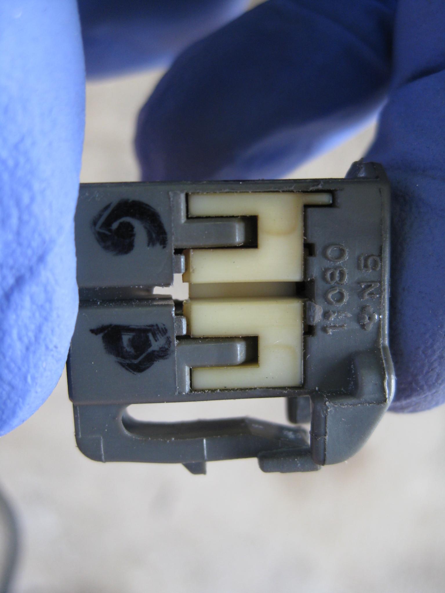
The difference between the S2 socket and the S1 connector is that the key slot is on the wrong side. What I did was use my Dremel tool with a cut off wheel to carve a new slot on the opposite side of the connector.
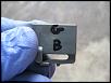
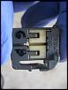
First, I labeled the wire colors on the connector before removing them. To me, they looked green and black, so I wrote "G" and "B" on the connector. However, I believe the "green" wire was blue discolored by gasoline.
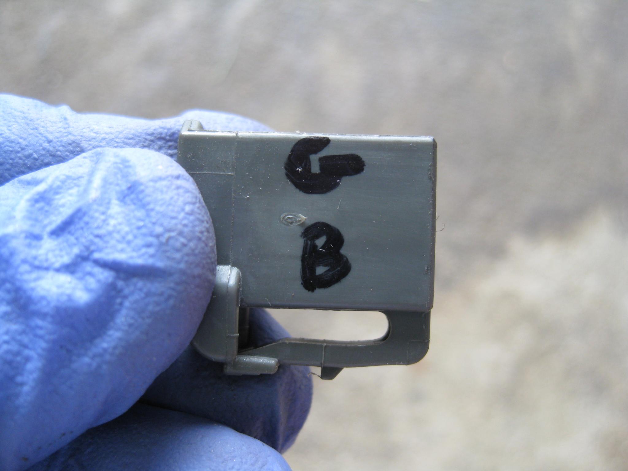
Then, there is a little white locking piece (at least that's what it seems to be to me) that I pried out, then removed the wires using a small screwdriver as mentioned in the original write-up.
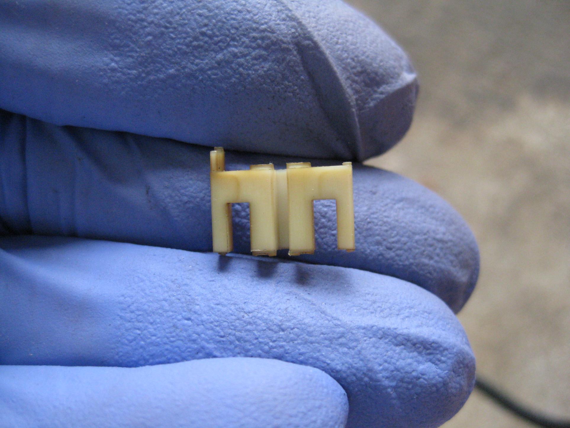
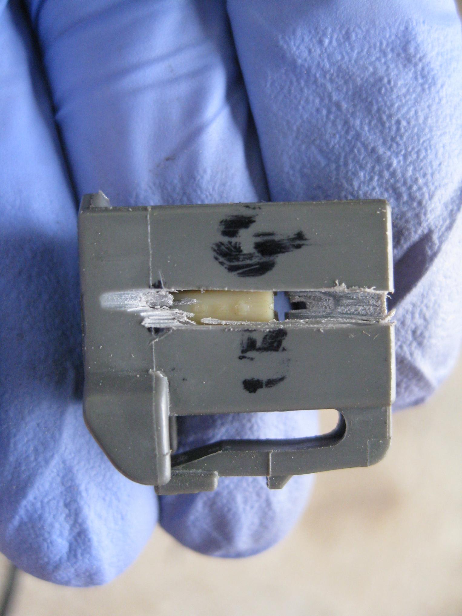
Then I used the Dremel to carve the new slot. I was afraid I would go all the way through and end up with a loose fit, so I took it in stages and test fit in the socket in the pump until I had it right. The cut off wheel made a lot of plastic slag, so I cleaned it up with a razor knife.
Once I was happy, I went to the car and swapped the connector. The wires in the tank were smaller and the terminal seemed slightly different, but it fit and my gas gauge works fine.
On installing the new pump:
The outlet of the S2 pump comes out at a different angle than the S1 relative to the FRONT arrow. I feel it would be to your advantage to rotate the pump to take any strain off of the outlet hose. I would suggest having the FRONT arrow on the pump indexed to about 2:00, where 12:00 is the indicated position facing the front of the car. This seems to jive with how the OP's pump ended up. Mine turned to about 1:00 during tightening and I may go back and adjust it to take some of the strain off the hose. I believe if you actually have the S2 pump installed according to the FRONT mark, it will be hard to get the outlet hose snapped back on without the risk of kinking the hose.
On tightening the ring nut:
As stated, this is a PITA. I used a rubber dead blow hammer and a concrete chisel to loosen/tighten mine. Look closely and you will see that there is an extra tab in one spot on the ring, between the regularly spaced ones. I marked that position before removing the nut so I'd have an idea of where to go back to. Mine was initially at approximately 1:00-2:00 (again where 12:00 is facing the front of the car). When reinstalling, the start position for that mark is about 9:00 and there is the word "START" imprinted on the gas tank. I assume that is to help get the nut started when you put it back on. There is "MAX" or "MAXIMUM" imprinted on the tank around the 3:00 position - apparently that is as tight as it will go - about 1-1/2 revolutions. I was only able to get mine to go to about 11:00 - not quite 1-1/4 revolutions. I've checked it twice this weekend with a full tank and so far, so good.
I should have taken more pictures. If anyone would like me to get the pictures, just say so and I'll go get them. I'll probably do it anyway eventually . . .
On re-using the connector from the Series 1 pump:
The difference between the S2 socket and the S1 connector is that the key slot is on the wrong side. What I did was use my Dremel tool with a cut off wheel to carve a new slot on the opposite side of the connector.
First, I labeled the wire colors on the connector before removing them. To me, they looked green and black, so I wrote "G" and "B" on the connector. However, I believe the "green" wire was blue discolored by gasoline.
Then, there is a little white locking piece (at least that's what it seems to be to me) that I pried out, then removed the wires using a small screwdriver as mentioned in the original write-up.
Then I used the Dremel to carve the new slot. I was afraid I would go all the way through and end up with a loose fit, so I took it in stages and test fit in the socket in the pump until I had it right. The cut off wheel made a lot of plastic slag, so I cleaned it up with a razor knife.

Once I was happy, I went to the car and swapped the connector. The wires in the tank were smaller and the terminal seemed slightly different, but it fit and my gas gauge works fine.
On installing the new pump:
The outlet of the S2 pump comes out at a different angle than the S1 relative to the FRONT arrow. I feel it would be to your advantage to rotate the pump to take any strain off of the outlet hose. I would suggest having the FRONT arrow on the pump indexed to about 2:00, where 12:00 is the indicated position facing the front of the car. This seems to jive with how the OP's pump ended up. Mine turned to about 1:00 during tightening and I may go back and adjust it to take some of the strain off the hose. I believe if you actually have the S2 pump installed according to the FRONT mark, it will be hard to get the outlet hose snapped back on without the risk of kinking the hose.
On tightening the ring nut:
As stated, this is a PITA. I used a rubber dead blow hammer and a concrete chisel to loosen/tighten mine. Look closely and you will see that there is an extra tab in one spot on the ring, between the regularly spaced ones. I marked that position before removing the nut so I'd have an idea of where to go back to. Mine was initially at approximately 1:00-2:00 (again where 12:00 is facing the front of the car). When reinstalling, the start position for that mark is about 9:00 and there is the word "START" imprinted on the gas tank. I assume that is to help get the nut started when you put it back on. There is "MAX" or "MAXIMUM" imprinted on the tank around the 3:00 position - apparently that is as tight as it will go - about 1-1/2 revolutions. I was only able to get mine to go to about 11:00 - not quite 1-1/4 revolutions. I've checked it twice this weekend with a full tank and so far, so good.
I should have taken more pictures. If anyone would like me to get the pictures, just say so and I'll go get them. I'll probably do it anyway eventually . . .
Last edited by Skywalker; Jun 9, 2013 at 08:00 PM.

Registered
Joined: Apr 2009
Posts: 918
Likes: 0
I'm a bit late to the party, but I put my Series 2 pump in a few days ago. Here are a few notes from my experience that may be useful to others.
On re-using the connector from the Series 1 pump:
The difference between the S2 socket and the S1 connector is that the key slot is on the wrong side. What I did was use my Dremel tool with a cut off wheel to carve a new slot on the opposite side of the connector.
First, I labeled the wire colors on the connector before removing them. To me, they looked green and black, so I wrote "G" and "B" on the connector. However, I believe the "green" wire was blue discolored by gasoline.
Attachment 196179
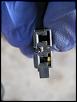
Then, there is a little white locking piece (at least that's what it seems to be to me) that I pried out, then removed the wires using a small screwdriver as mentioned in the original write-up.
Attachment 196180
Then I used the Dremel to carve the new slot. I was afraid I would go all the way through and end up with a loose fit, so I took it in stages and test fit in the socket in the pump until I had it right. The cut off wheel made a lot of plastic slag, so I cleaned it up with a razor knife.
Attachment 196181Attachment 196182Attachment 196183
Once I was happy, I went to the car and swapped the connector. The wires in the tank were smaller and the terminal seemed slightly different, but it fit and my gas gauge works fine.
On installing the new pump:
The outlet of the S2 pump comes out at a different angle than the S1 relative to the FRONT arrow. I feel it would be to your advantage to rotate the pump to take any strain off of the outlet hose. I would suggest having the FRONT arrow on the pump indexed to about 2:00, where 12:00 is the indicated position facing the front of the car. This seems to jive with how the OP's pump ended up. Mine turned to about 1:00 during tightening and I may go back and adjust it to take some of the strain off the hose. I believe if you actually have the S2 pump installed according to the FRONT mark, it will be hard to get the outlet hose snapped back on without the risk of kinking the hose.
On tightening the ring nut:
As stated, this is a PITA. I used a rubber dead blow hammer and a concrete chisel to loosen/tighten mine. Look closely and you will see that there is an extra tab in one spot on the ring, between the regularly spaced ones. I marked that position before removing the nut so I'd have an idea of where to go back to. Mine was initially at approximately 1:00-2:00 (again where 12:00 is facing the front of the car). When reinstalling, the start position for that mark is about 9:00 and there is the word "START" imprinted on the gas tank. I assume that is to help get the nut started when you put it back on. There is "MAX" or "MAXIMUM" imprinted on the tank around the 3:00 position - apparently that is as tight as it will go - about 1-1/2 revolutions. I was only able to get mine to go to about 11:00 - not quite 1-1/4 revolutions. I've checked it twice this weekend with a full tank and so far, so good.
I should have taken more pictures. If anyone would like me to get the pictures, just say so and I'll go get them. I'll probably do it anyway eventually . . .
On re-using the connector from the Series 1 pump:
The difference between the S2 socket and the S1 connector is that the key slot is on the wrong side. What I did was use my Dremel tool with a cut off wheel to carve a new slot on the opposite side of the connector.
First, I labeled the wire colors on the connector before removing them. To me, they looked green and black, so I wrote "G" and "B" on the connector. However, I believe the "green" wire was blue discolored by gasoline.
Attachment 196179
Then, there is a little white locking piece (at least that's what it seems to be to me) that I pried out, then removed the wires using a small screwdriver as mentioned in the original write-up.
Attachment 196180
Then I used the Dremel to carve the new slot. I was afraid I would go all the way through and end up with a loose fit, so I took it in stages and test fit in the socket in the pump until I had it right. The cut off wheel made a lot of plastic slag, so I cleaned it up with a razor knife.
Attachment 196181Attachment 196182Attachment 196183
Once I was happy, I went to the car and swapped the connector. The wires in the tank were smaller and the terminal seemed slightly different, but it fit and my gas gauge works fine.
On installing the new pump:
The outlet of the S2 pump comes out at a different angle than the S1 relative to the FRONT arrow. I feel it would be to your advantage to rotate the pump to take any strain off of the outlet hose. I would suggest having the FRONT arrow on the pump indexed to about 2:00, where 12:00 is the indicated position facing the front of the car. This seems to jive with how the OP's pump ended up. Mine turned to about 1:00 during tightening and I may go back and adjust it to take some of the strain off the hose. I believe if you actually have the S2 pump installed according to the FRONT mark, it will be hard to get the outlet hose snapped back on without the risk of kinking the hose.
On tightening the ring nut:
As stated, this is a PITA. I used a rubber dead blow hammer and a concrete chisel to loosen/tighten mine. Look closely and you will see that there is an extra tab in one spot on the ring, between the regularly spaced ones. I marked that position before removing the nut so I'd have an idea of where to go back to. Mine was initially at approximately 1:00-2:00 (again where 12:00 is facing the front of the car). When reinstalling, the start position for that mark is about 9:00 and there is the word "START" imprinted on the gas tank. I assume that is to help get the nut started when you put it back on. There is "MAX" or "MAXIMUM" imprinted on the tank around the 3:00 position - apparently that is as tight as it will go - about 1-1/2 revolutions. I was only able to get mine to go to about 11:00 - not quite 1-1/4 revolutions. I've checked it twice this weekend with a full tank and so far, so good.
I should have taken more pictures. If anyone would like me to get the pictures, just say so and I'll go get them. I'll probably do it anyway eventually . . .
great detailed writeup on the connector!!!
heres a vote on getting those extra pictures~!!! Goodjob!


I finally reached the end of my fuel pumps life last summer and just put in my order for my Series II pump. I will be performing the swap within the month (its cold here right now so Im not very concrete on the actual time frame)
If anyone is interested in doing this swap themselves and would like any further information and/or pictures that hasnt already been discussed/posted let me know and I will gladly post them here on this thread.
If anyone is interested in doing this swap themselves and would like any further information and/or pictures that hasnt already been discussed/posted let me know and I will gladly post them here on this thread.
Finally got around to installing the Series 2 fuel pump in my 2004 RX8. Here are a few pictures, hopefully they help the next guy looking to do this.
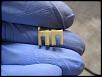
In these you can see where the electrical connector is located to use in the new pump. You can see where the connector needs to be modified to fit into the socket of the new pump. In doing this you shouldn't have to cut or splice any wires on the vehicle, just pop out the pins from the factory connector and put them in the modified connector. The pins will not snap in tight in the connector but with care you can get them to seat on the pins on the fuel pump, they will be snug when plugged in. Pay close attention to where the two wires went on the stock pump to ensure you do not mix them up. Pretty simple stuff here.
In these you can see where the electrical connector is located to use in the new pump. You can see where the connector needs to be modified to fit into the socket of the new pump. In doing this you shouldn't have to cut or splice any wires on the vehicle, just pop out the pins from the factory connector and put them in the modified connector. The pins will not snap in tight in the connector but with care you can get them to seat on the pins on the fuel pump, they will be snug when plugged in. Pay close attention to where the two wires went on the stock pump to ensure you do not mix them up. Pretty simple stuff here.
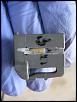
Ok so here we have the inlet hose. I did not particularly like the way others had been doing this. If using submersible fuel hose and worm clamps is your only choice then ok but that isn't really the way to do this. I have the luck of having a fuel line repair kit at my disposal though my work. Basically you cut the factory quick connect elbow off the inlet hose right at the quick connect making sure you have a good clean and straight cut. Install the tool to the cut line and crimp on a new quick connect elbow that fits the nipple on the new pump of course. This way you have a solid mod that has no way of leaking, unless of course you mess up the crimp, but in that case you can just cut off your new elbow and try again making sure you cut off as little of the hose as possible.
I didn't take any pictures of the stock inlet hose, as they are on this thread already, but in the second pic on this post you can see the new larger quick connect elbow cleanly crimped onto the the factory hose, now it snaps right to the new pump like it was meant to be.
I didn't take any pictures of the stock inlet hose, as they are on this thread already, but in the second pic on this post you can see the new larger quick connect elbow cleanly crimped onto the the factory hose, now it snaps right to the new pump like it was meant to be.

The hose in the tank is from the siphon assembly on the other tank saddle. It has no pressure. An orifice in the internal bypass of the main pump assembly siphons fuel from the other saddle side into the side with the pump through this line inside the fuel tank. While an OE style connector is nice as per the post above, it us not really critical if performed properly as described in the DIY procedure.


Because a Walboro or Deastschwerks in a S1 assembly doesn't work as well as a S2 pump assembly. I still had fuel starvation at 1/2 tank with a 255 Walboro from BHR in my S1 pump assembly.

Be advised that the parts listing for the S2 fuel pump has changed from what was originally posted on the forum back in 2009. In addition to buying the entire fuel pump assembly you can also buy the following individual fuel pump components separately; the main filter housing, the bypass regulator, the fuel pump, and the sock. Initially the pump was not available separate as it is now and the part numbers changed for the entire fuel pump assembly and the pump itself.

Registered
Joined: Dec 2010
Posts: 229
Likes: 0
From: Dearborn Heights, MI
I recently installed a Deatschwerks pump in my S1 and still have a starvation issue when there is less than 1/4 tank of fuel. If I find an S2 pump assembly can I just reuse the DW pump since I already paid for it?


what would you do to the OE fuel pump housing assembly to try and improve it's performance in low tank volume situations
Registered
Joined: Dec 2010
Posts: 229
Likes: 0
From: Dearborn Heights, MI
Well in my case the fuel pump motor was a major contributor of the problem. I couldn't drive for more than 30 min without starvation issues even at very low demand such as light acceleration. The car would fall flat on its face.
With the new pump the issue is mostly resolved but it's still not perfect. Before I replaced the pump I read this thread, the Esmeril DIY, and the MazdaManiac thread and since my issues only started after a track day with 96 degree ambient temps I thought the pump was fried.
I'm really not asking to be spoon-fed but thanks guys. I'll look around for more info.
The easy answer...keep the tank above 1/4
There are a few options.....a passenger side pump filling the drivers side cup will work for a bit longer...but will still starve out long before the tank is empty in high G loads
The only sure fix I have found is a surge tank and an external pump...with enough volume it can survive when the low pressure pumps slosh out of fuel
Or a fuel cell with a proper sump...
Problem is that there are rules for a lot of racing series that won't let you do either