When you click on links to various merchants on this site and make a purchase, this can result in this site earning a commission. Affiliate programs and affiliations include, but are not limited to, the eBay Partner Network.
Oh man, finally able to have some time to reflect on this. First things first I guess I should start out by saying I didn't actually expect to be going to the track this weekend, but the stars aligned, my friend offered to trailer the car, and was ready to wheel the RX-8 around for the first time with full expectation of having a subframe fall off at over 100mph.
Well, luckily none of that happened and I am happy to report the only thing I don't like about the car is the lack of power! The thing has SO much grip it's insane.
Let's start back at midnight the night before I had to be up at 5am to tow the car to Grattan. The car wouldn't fit on the uhaul we had rented.. too low.. bumper was hitting.. and the bolts for the roll bar were extended down like 1/2 an inch too far. I KNEW that was going to be an issue when I had first installed it, and here we are at midnight trying to load the car on the trailer.
Took an angle grinder to the bolts to shorten em a bit, and that did the trick.
Finally, the stressful part was over and I could do my shakedown.
Another thing to note was that I had:
-Never driven a RWD car (that I owned) on track
-Never driven at this track
-Driven the RX-8 about a total of 30 miles before today
-Eyeballed the alignment
A lot to think about.
Either way, the car did great. There was tons of grip.. and I couldn't make it go faster to use it all. The brakes are fantastic, the suspension needs some attention.. but that could just be an alignment.
The track was even better, such good flow and height changeups.
It was between 88-92 ambient the entire day, and my only complaint was that I did get water up to 235*F before backing down. Definitely need to address cooling (more on that in a bit). I wasn't able to log engine parameters or anything else except bad time timing with my phone. Kinda bummed but I didn't get it all done in time. Reasons.
Here's a session my lap timer did manage to work. Notice the awful interpolation of speed/Gs. The 1Hz GPS though seems to work better with a slow car though!
Alright, so what's the plan moving forward from this shakedown
Addressing cooling:
-I want to get the Racing Beat REVi and duct out of there, make more room for airflow through the radiator. I have a plan to chop up an AEM intake for (probably less power, oh no -1hp!) routing through the bumper.
-Battery moved to truck, again more airflow through rad
-Ordered a Mazdaspeed replica bumper, should suck in more air in theory?
-Changeover coolant to water, blehhhh will do this eventually
-Turn fans on at lower temperature with the ECU cal (seems to be common?)
-Stock undertray goes back on, this LRB **** is literally trash.
-GET MY DAMN GAUGES IN, at this point I may give up on the CAN integrated display and just slap some Defis I have laying around in.
With all these things done, I can then dive down the other alleys of water pumps and thermostats and blah blah all that.
Suspension:
-Align the damn thing properly
-Sway bars, little too much body roll for the spring rate IMO
-Replace some bushings, eventually
Would also like to try and get rid of some more weight, but I also would just like to keep driving the car. In absolute love with the chassis!
Some more glamor shots from my friend who's SUUPER handy with a camera
Great to hear how much you enjoyed it after putting in so much effort .
You should have a read up on airflow theory .... It's less about how big the opening is and more about holding the air you do capture so it goes where you want it .
Great to hear how much you enjoyed it after putting in so much effort .
You should have a read up on airflow theory .... It's less about how big the opening is and more about holding the air you do capture so it goes where you want it .
Yeah! Ducting would be really nice to properly do, and I am looking into it.
I've got a pretty rad 3D scanner at work I want to borrow for a weekend and get some reference geometry and start cadding some stuff up.
In the mean time, being a bit less scientific and more "practical" I think just removing the airbox and battery in the way of the airflow from the rad should at least give me a fighting chance. The MS bumper was mostly for looks anyways . I did go out and buy some OEM "fog light" brackets so that it can channel the air properly to the oil coolers too. I hope the rep bumper works with them.
Some other stuff I have been up.. dzus fasteners on the undertray + quick latches on the bumper should make removal and install super easy.
Kind of just mocking this one up while I wait for the MS bumper.. don't really like the side latches, and the corners obviously still need to be addressed, but it definitely makes it easier to remove the bumper. Will think this through more with the new bumper. As you can also see, the ebay quick connect buttons were tried.. but a huge fail. I don't know, this is my first time building race car stuff! Mud guards will also probably come out, unless someone can convince me they help channel air through the coolers and brakes better.
Also in my practical attempt at better cooling, I decided I should remove the AC. I can't recall why I didn't before when I did the Koyo... but it's all gone now, lines, compressor and all!
Oh, and I removed the CD player! NOW we are good to PROPERLY race without that weight
Also in my practical attempt at better cooling, I decided I should remove the AC. I can't recall why I didn't before when I did the Koyo... but it's all gone now, lines, compressor and all
I just spent DAYS deliberating over this myself. I actually drive mine around a fair bit but had cooling issues last time on track as well so finally bit the bullet . Almost got a face full of compressor oil for my trouble..........didn't realise how much pressure they hold !
Yeaaaaaah just a time vs money thing here. Would take me twice as much cost in my time for me to make something on point, though I could justify it by refining my aluminum TIG skills... hmm...
Either way I got the 90 degree 3.25in aluminum tubing in the mail today.... so..probably just gonna end up buying one in a few weeks when the new bumper arrives.
I’m not scrutinizing anybody, I’m sharing 15 years of experience with you. I’ve built pretty much every variation of CAI possible for this car. You can go to the DSP thread to see my latest version.
Thanks for making my point though; what part about “it’s not really a good intake imo” didn’t you understand?
The OE Mazda tube is essentially 3.5” OD x 0.063” wall thickness (86mm or 3.375” ID) and is very short. As an engineer you should understand that with a tube length 6x (just guessing) longer that the last thing you want to do is add further restriction with a smaller ID tube and filter. There have been plenty of arguments made against that; ignorant as they are imo.
I�m not scrutinizing anybody, I�m sharing 15 years of experience with you. I�ve built pretty much every variation of CAI possible for this car. You can go to the DSP thread to see my latest version.
Thanks for making my point though; what part about �it�s not really a good intake imo� didn�t you understand?
The OE Mazda tube is essentially 3.5� OD x 0.063� wall thickness (86mm or 3.375� ID) and is very short. As an engineer you should understand that with a tube length 6x (just guessing) longer that the last thing you want to do is add further restriction with a smaller ID tube and filter. There have been plenty of arguments made against that; ignorant as they are imo.
.
OEM Mazda tube isn't 3.5in, which actually surprised me seeing as everyone uses these intakes without rescaling the MAF. To be fair on that same point, the Racing Beat intake I have on now is 3.5in and I haven't seen any crazy fuel correction. These are actually the same MAF, and I presume same base software as the Subaru ECUs, and there is nothing but issues if you change the MAF housing diameter and don't rescale it with those. My guess is that with the addition of possible positive manifold pressure on the Subaru, the range of the MAF is higher and thus resolution is much lower for the same use case. I have no idea, point is that it blows my mind no one seems to be rescaling these sensors.
There are benefits of having a smaller inlet to a larger outlet on an intake, but I can't speak to those specifically because that's not my area of expertise and I'd probably just be lying. So maybe it's worse, maybe it's better, either way I don't care because like I mentioned before I couldn't care less about power. As long as air is getting into the engine and the MAF is scaled properly, I am happy. If I wanted to make power, I wouldn't use an MSP engine. It's not worth cranking up to 11 compared to other engine options. I am just mimicking the AEM intake as much as possible for simplicity. I don't care about redefining the air intake for an engine that's already not moving a huge amount of air. I do understand going nuts on it when bound to a rulebook like in DSP, so I appreciate the commitment.
Okay, still work to do on this but it's mainly installed. I think I've posted a bit about these before so I'll just cut to the chase.
To be perfectly honest this level of integration is a bit overkill for a race car and I aboslutely could have just plopped some Defi gauges I have sitting on the shelf onto the dash and been perfectly happy with it.. but I wanted a bit of a challenge to both make something cool, but more importantly test my skills. Before I started this I had never design and created my own PCB before, and also struggled to make CAN hardware work (well) with software.
So first things first, I wanted a full integrated gauge screen inside the OEM cluster which looked like it came there from the factory. There was a lot of dead space under the fake oil pressure gauges so I figured it could use some population.
Cool, we have concept and an end goal. Now to get to that goal..
I designed a basic interface to both poll CAN data already on the bus (water temp) and then to look at CAN data from my own sensors. CAN data that was already available was simple, we just needed to reverse engineer the broadcasted CAN data and create an interface to receive it. Simple and easy. My own sensors were a bit more challenging, but at the end of the day we needed to put our own sensors on the bus, so we knew we could assume the end controller would just see it as a bus message. This allowed me to get going on some bench builds and development boards.
I decided to use an OLED screen simply because I needed the screen the blend in with the background of the cluster. And LED or LCD screen would have an awful backline sheen and that was just not acceptable. Lucky, Adafruit makes some pretty rad dev boards with a perfectly sized OLED screen for the job.
Next up was creating some interfaces to write arbitrary sensor data to the screen. Pain in my ***, because graphics are hard, but I came up with something like this. One thing to note is that you really only want to change the pixels that are actually changing otherwise you end up bad screen flashing, bad refresh rates, or your background getting blasted out by uncleared pixels. Display logic isn't really relevant to this forum I suppose, so tl;dr it was a pain in my *** but very much so worth it.
I also cruised around the interwebs looking for some fonts that matched the cluster's font style. I settled on this font and ported it over to the code. The font actually takes up the most memory -_-, but again I think it's worth it.
Cool, so we had a bench device and some basic software that worked... how to we get this thing into the cluster itself? Well.. we start BLASTIN! Also we pull up CAD.
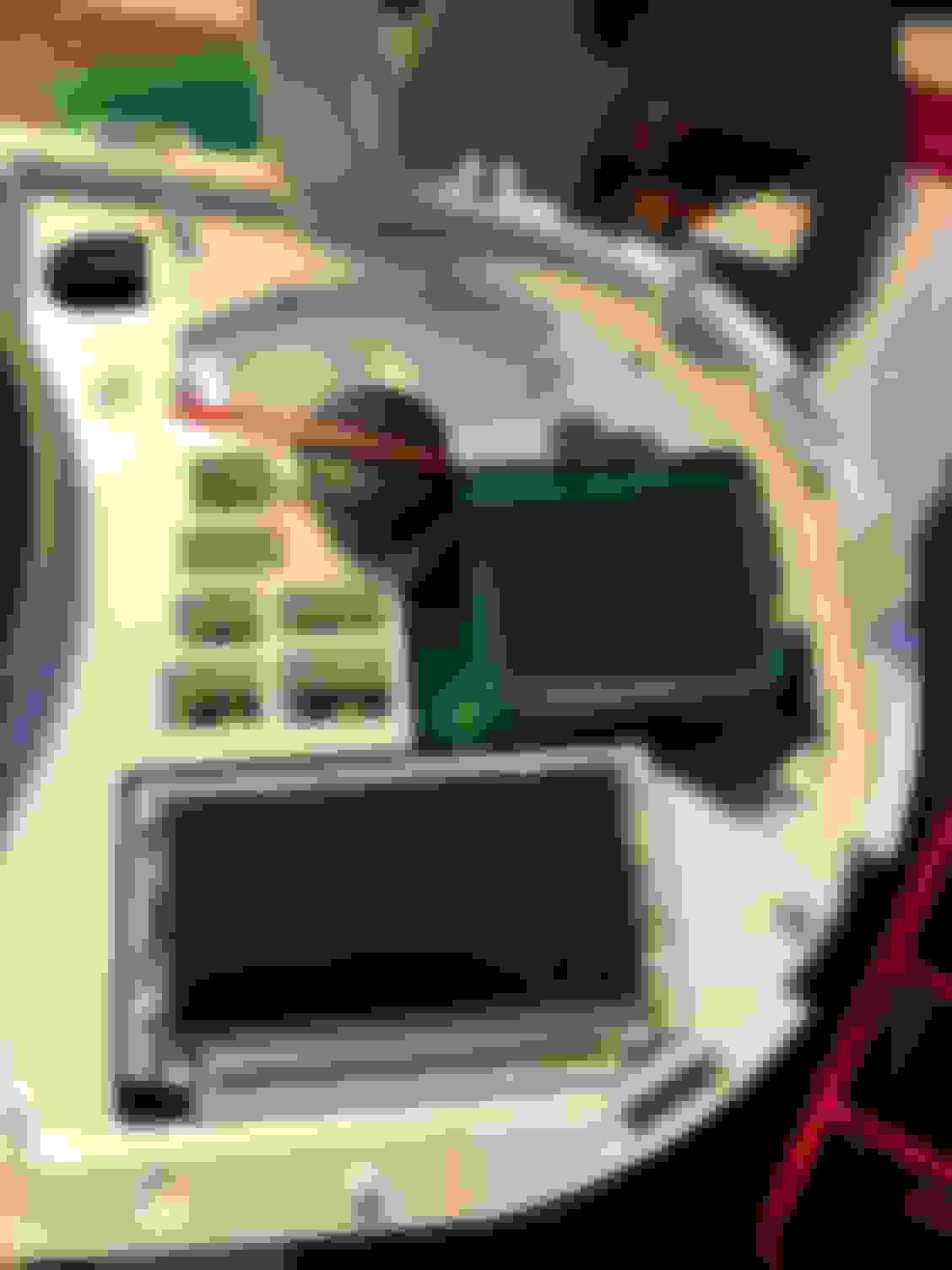
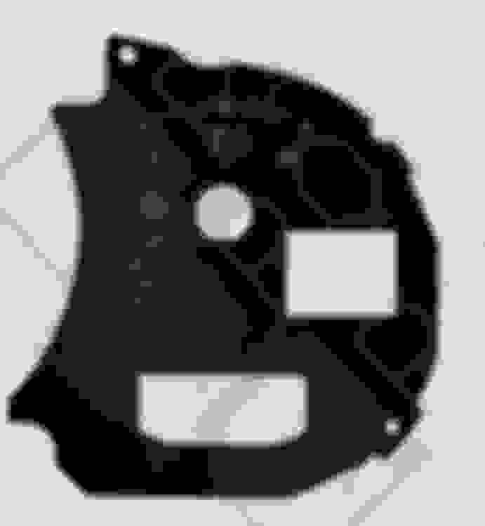
Inside the cluster we can see a perfect spot once you trim away all of the garbage we don't need. In order to index and affix the screen properly, I needed a constant set of geometry that would always be the same no matter what. I found some through holes in the cluster PCB that did the trick well.
With this geometry we can then CAD up a mount with that pattern and then we will always have a constant place to pop our hardware into. To get that geometry right in CAD, I traced it on some paper, added a basic set of known dimensions and iterated about 3 times until I had a piece that popped right in like the last piece of a puzzle. From there is was just getting the rest height of the screen right, and a mount that held the screen tight. I think I did about 10 design revisions until I had it perfectly. Awesome. Now for the circuitry..
I needed a daughter board that popped into the cluster and both drove the CAN receiving and the display. Went a bit ham, and created a full PCB (with bad circuit protection) to do both. I basically stole the design of my bench build and dev boards, thinned out the stuff I didn't need, and then aligned it on a board that would fit inside the cluster. I went with a pretty basic piggyback on an Atmel 328P with a SPI screen (from Aliexpress, hell yeah Chyyynaaaa) and SPI CAN MCU. Bit expensive by bulk productions standards, but it made my life simple.
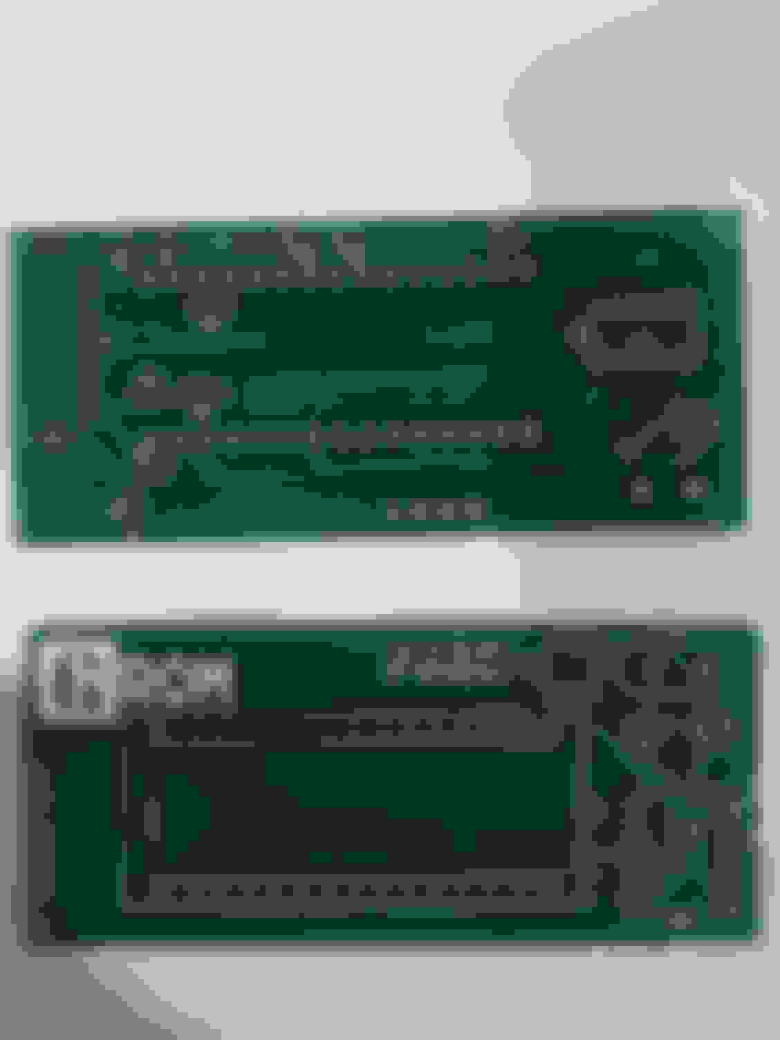
Generated the right files, emailed them over to a PCB manufacturer and in a few days I had this guy.
Populated the board with the components and BAM! As you may see there is a V2 rev in the silkscreen.. it's actually a V3 rev... tl;dr making your own stuff is hard.
Alright. Cool. We had a board, and we had mechanical mounting for the screen. Mechanical mounting for the board inside the cluster was next. Again, bang out the CAD, find some reference geometry, print stuff until it works, and BANG
The cover pops on and everything is secured into the unit. You can plug it into the car as normal, and you're good to go. CAN ties in at the cluster, and power is with key on like the cluster as well. But as you may notice there needs to be a hole cut in the insert in a very specific spot... how do we do this.
Well, I had a plan to silkscreen my own inserts, ask a company to do it for me (spoiler: they wanted too much money) so either way I had to design and make dimensions for my own insert. I did this by scanning in the OEM insert and getting it vectorized. I made some basic cuts in the factory one and then used some electric tape to mask exactly where it needed to be with my screen in place. From there I applied those dimensions to the vector drawing and could now print out perfect templates to test as seen in the photo above.
Like I mentioned, in a perfect world I would have these made or inserts properly cut (trust me, I almost bought a 40W laser cutter just for this project), but I needed to get this moving so I ended up just using the printed out insert as a template for cutting the factory insert in my other cluster.
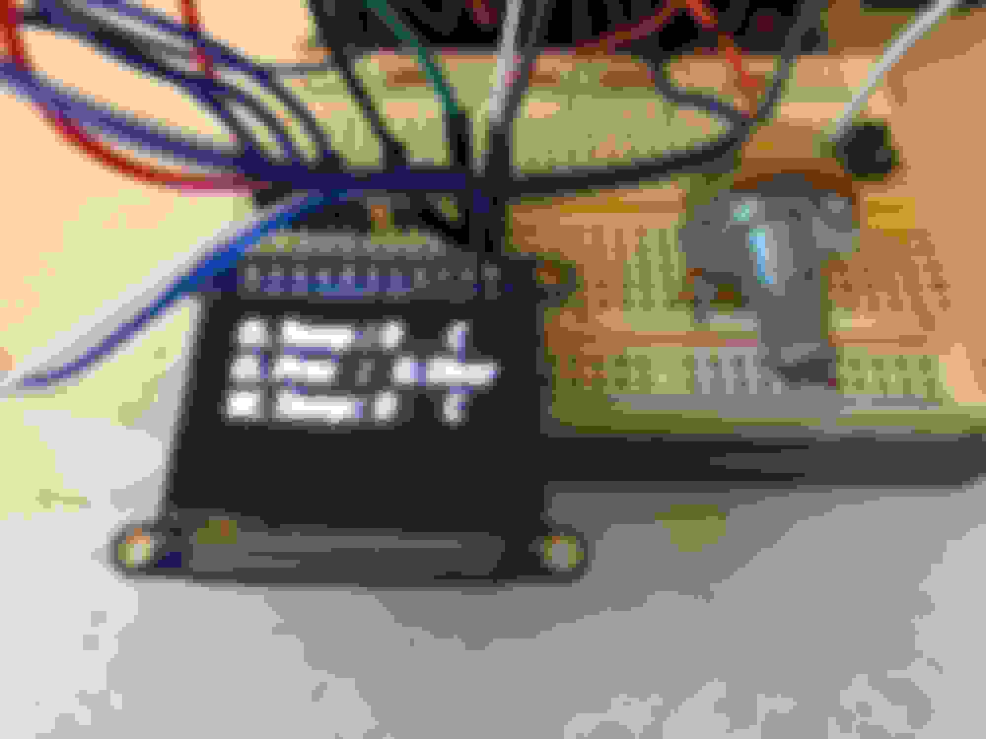
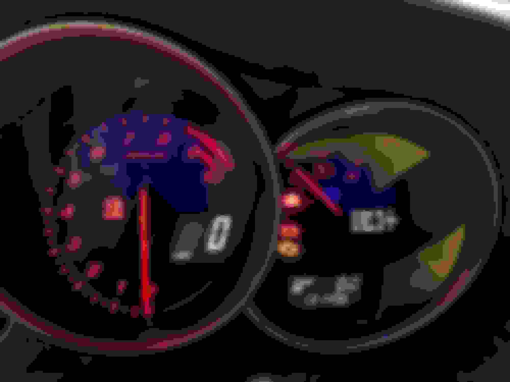
Aaaaaaaaand look what we have!
This "end result" kind of leaves out the details of the two clusters I nuked in the process, as well as me swapping over my cluster's odometer to the new cluster by reprogramming the factory cluster EEPROM so there was full continuity. The car has no idea a completely new cluster is in it, and nor does anything else! Also, don't mind the wonky oil pressure.. the sensor isn't working properly in this picture... which leads me to sensors.
Sensors were actually done using the exact some board I made above, after all we just need something that can read sensor and broadcast CAN. That board can do it with a bit of an input change, and a complete software overhaul. I am working on another board revision to be able to handle everything better, but the tl;dr is that software with the same hardware is RAD. Basically I just did analog to CAN conversions (with some MEH filtering) and then broadcasted them out on my own new CAN message to the entire vehicle. My cluster then picks up that message and signals and parses them back into engineering units for display. Woo!
I'm pretty happy with both the performance, and style of everything. I think it matches great and the only thing left on the table is software to be able to change parameters (technically to literally anything you'd want) and/or units, as well as fixing the pressure sensor.
sigh ... 3.5” OD is just the standard available that get’s you close to what really matters; the ID, which is what was also provided. edit; deleted improper comment spoken out of frustration.
pretty cool little gauge dash, but kinda small. probably hard to look at when you're doing 120 mph on the track. cool engineering exercise tho.
Yeah we will see! I am used to looking at 45mm gauges in a center pod, so hopefully this isn't any worse.
I forgot to add I did put some software in that the gauges will change to red as a warning if they exceed a threshold value. That should aid a bit in viewing too.
Whelp since this thread has devolved into "barely races, just plays with 1s and 0s" because I am just waiting on parts nowadays, I guess I'll post this here.
Was able to get the cluster on my bench to count up the odo, something I feel a lot of swap guys don't have. Kinda of complicated way the signal works, but hey, look at the numbers change!
Well, I tired to do some work on the car by adding a bumper and an intake... been set back because KBD stuff is actual garbage, and filters that fit are all on backorder because of COVID -_-
KBD Mazdaspeed rep was a floppy pile of trash. I expected just regular trash, but this wasn't even worth the time to make it work. Undertray was probably 2-3 inches out from even being able to bolt up, middle section was about an inch too wide, and the oil cooler openings were about as warped as a house in the California fires right now. They still even had a plate imprint on the outside of the bumper face.. like cmon...
Anyways, I was able to return it and I am still waiting for my refund to process. I had to call them to start the return process after I had received notification they received the bumper back over a week before I called. It's been 5 weeks since the return process was started. Pain in the ***, 2/10 would not recommend to a friend.
On the intake side of things, I did buy an AEM intake to clear up some room behind the radiator and got the 90 degree piece mounted up with some printed ABS parts. I went to buy an AEM filter and the clearance is just not there for it. I then specced out a smaller sized Green filter, but am still waiting on them to ship it after two weeks. They did say everything is delayed because of Covid so, fair enough. I did see some other guys using a K&N part number which I may just pick up and cancel the Green order if this goes on too long.. but for now I just have the AEM intake running the AEM filter in the intended AEM location since I have an event coming up and a filter would be a stupid reason to not have the car available.


 . I did go out and buy some OEM "fog light" brackets so that it can channel the air properly to the oil coolers too. I hope the rep bumper works with them.