When you click on links to various merchants on this site and make a purchase, this can result in this site earning a commission. Affiliate programs and affiliations include, but are not limited to, the eBay Partner Network.
r3mix. The car has much more vibration and noise than it originally had. No surprise there. I am also running the coilovers at the stiffest compression and rebound setting which makes the ride on the harsh side of things. While racing I like the very stiff suspension and the limited body roll. With that said, on the street where I drive the rest of the time, I find myself wanting to soften things up a bit. I'm one of those people that dislikes buzzing and rattling in cars and of course with this suspension it is somewhat the cost of doing business. I haven't started chasing the biggest offenders yet, but that day is approaching. One plus side for me is that I can switch to my M4 which gives me a different type of power and driving characteristic when I want a softer ride on the street (still fun though).
I like the change to the Wilwood calipers. They give me good preliminary bite but their not so aggressive that it has dramatically changed the behavior of the breaking system. I am using the stock stability control module and antilock braking system and the system behaves nicely even when driving at the limit. Note: I driven it in autocross sessions but not on the road track yet. So, I haven't really pushed enough heat into the system to have brake fade problems. I'm sure when I get it out on the track I will experience brake fade when driving hard. I still got lots to learn and I think the car has room to grow with me.
I'm the same way with rattling and buzzing etc. I'm running higher spring rates for various reasons such as a boat anchor engine lol. 12k front and 10k rear. Probably could have gotten away with 10/8 but whatever, rides well enough all things considered. I'll probably never use my brakes to the same degree since I just daily it with spirited driving every so often. The OEM brake setup is ok but clearly doesn't like the weight imo.
Thanks for the pricing breakdown, that is very helpful. Are you trying to aim higher than the 300whp estimates? I've been down the lfx rabbithole and built up a parts list to aim for 350whp, unfortunately the LFX tuning scene is weak up in the north east. There might be some Australian tuners who do remote tuning, the lfx scene seems to be most active down there.
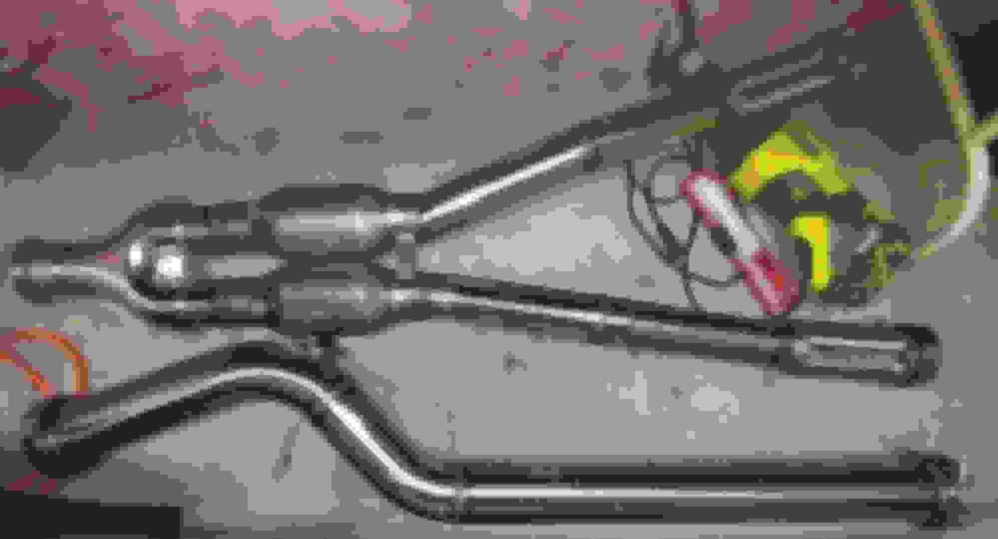
I was focused on completing the swap instead of making meaningful changes in the engine performance levels. However with that said, I did opt for the high flow cat configuration of exhaust that Andrew offers as an option. Picture provided below.
Y-pipe and mid-pipe exhaust configuration offered by Andrew as an optional product.
In addition to that, I purchased one of the JacFab LaminatorFX inlet cavity fillers and modified stock inlet by removing airflow waffle and grinding down the resulting nubs. Their testing indicated that they could increase the inlet flow levels by as much as 17% with this modification. The cost of the mod was less than $100. The youtube video that describes this system can be found at the following link:
I haven't had the car tuned yet. I've spent some time looking for dyno-tuners locally. This has led to a wide range of prices ($500 - $1500) with limited references I can draw upon to be confident with the product I'll get. At this point the car is running reasonably well. However, I do still have plans to tune it. Like you I have found that there are less options relative to tuning for the LFX configuration. More effort appears to have been placed on the V8 cousin (no surprise).
After installing the new seals, bolt hole grommets, and replacing the valve cover gaskets, I was ready to reinstall the valve covers. Note: You will need to apply a couple small dabs of RTV sealant at the joints between the timing chain cover and the forward edge of the cylinder head. I used "TheRightStuff" rtv for all of the RTV-based sealing requirements I had (new back cover on differential, oil pan, sealing on valve cover joints, etc).
Diagram showing valve cover tightening sequence and at the top one of the interface points to apply RTV sealant is pointed out. Bolts should be tightened to 89 inch pounds (it might be prudent to torque these in two steps 44 in-lbs followed by 89 in-lbs but I think i completed this in one step without later incidents). Recall these are aluminum heads, it is not necessary or desirable to over-torque these bolts. I did however, chase these threads before reinstalling the valve covers.I think this specific picture is for the LLT version of this engine but believe that the same sequence and tightening pattern applies to the LFX.
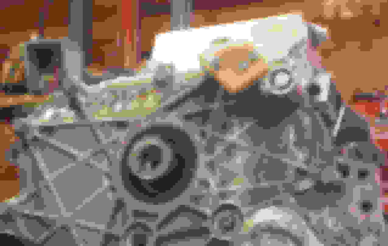
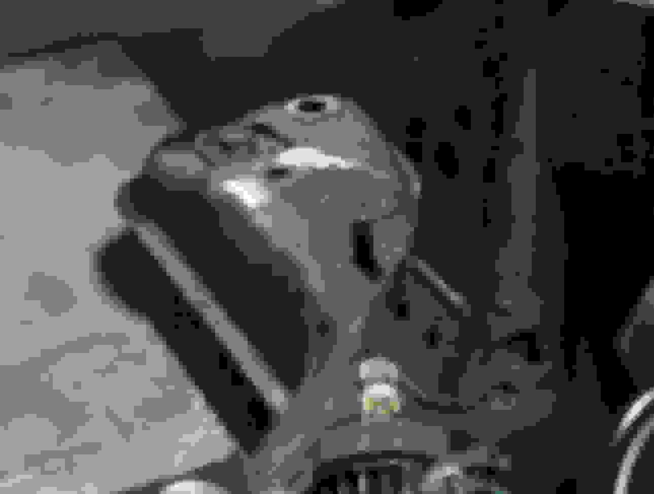
The next order of business was to pull the LFX oil pan and replace it with the modified oil pan provided in the LFX Swap Kit by Andrew. I'll point out again that as a part of the kit Andrew provides 15 detailed videos that walk through much of the engine swap process. This is in addition to the many parts Andrew has developed for the kit. Because of my poor documentation of the oil pan removal and replacement, I've chosen to pull a few still pictures from one of these kit videos which capture the high points of this process. The first order of business was to recognize that you are required to pull the harmonic balance pulley in order to pull the oil pan, as the three bolts which pull the oil pan up against the bottom of the timing chain cover are secured from the front of the timing cover. While two of those bolts are easily reachable, the one in the center is located directly behind the harmonic balance pulley. Fortunately, this pulley it (1- keyed, and 2-comes off easily with a proper puller). I was able to get a three arm puller from Autozone, pull and reinstall the harmonic balance pulley without having to buy this puller.
Harmonic balance pulley with mounting bolt removed prior to applying puller. Note: While the center bolt partially hidden just below the pulley looks like you might be able to sneek it out... you can't. This pulley must be removed to pull the oil pan. Notice the keyway on the pulley that provides alignment for reassembly. Prior to installing the puller, you will want to reinstall just the mounting bolt (or equivalent sized bolt to act as a anchor for the center puller bolt to press against. Otherwise you might damage the threads on the crank. Then you can just back out the pulley with the puller. There are 13 mm bolts which secure the bottom of the oil pan and a couple of 10 mm long bolts that secure the back of the oil pan. Finally, you have to remove the three 13 mm bolts that secure the front of the oil pan through the timing belt cover. Once all of the bolts, securing the oil pan, have been removed; you can use the reliefs along the side of the oil pan to release the RTV sealant holding the oil pan to the bottom of the block Once you've released the original oil pan, you can begin to clean up the oil pan mating surface. One thing to note: There are two alignment pins which help to locate the oil pan with the bottom of the engine block. It is possible that one or more of these pins will stay with the oil pan cover rather than remaining in the block. So, check to make sure to remove any alignment pins which stayed with the old pan and reinstall them in the proper locations on the bottom of the block. As suggested in the swap videos, it is best to turn the engine over so that the block mating surface is pointed toward the ground before you remove/clean up the old residual RTV that has stayed attached to the bottom of the block. This is also a good time to use a thread chaser to clean up all of the bolt holes to make reassembly easier.
Note: You don't need to clean up the old RTV on the original oil pan surface because you will not be reinstalling the old oil pan. Andrew includes a new modified oil pan (which is the reason we are doing this). I decided to buy the newer modified baffle oil pan that Andrew designed to ensure that oil returned to the oil pan was primarily store in a confined region around the oil pickup tube. This new part is a completely new casting which resulted in a really nice part which bolts up directly to the LFX block. There were no fitment issues with this new part. Every bolt hole lined up exactly and since the new part is a complete casting, there are no cut and welded surfaces. Once installed it looks like the engine came that way from the factory.
Once the oil pan and block mating surfaces have been cleaned on any old RTV, I made sure to clean the surfaces with some brake cleaner and a mild scrubbing with a white scotchbrite pad. Then I used THE Right Stuff RTV along the new oil pan mating surfaces. Note that you do not want to apply RTV to the narrow ridge along the front of the oil pan. It is actually the front of this region of the oil pan which mates to the timing cover. The oil pan in this picture is the older oil pan design Andrew provided in the earlier kits.The newer cast oil pan I used required an additional purchase cost due to the added design and manufacturing expense. The price bump was minor and the new cast oil pan is really nice. I would buy it again. This picture shows application of new RTV to the mating surface of the timing cover. Note: You want to add small dabs of RTV at the mating interface between the timing cover and the bottom of the block. You also want to add small dabs of RTV at the rear seal interfaces at the back of the block to ensure that these locations do not leak oil after reassembly. Once the RTV is applied to all the mating surfaces, you want to carefully locate the new oil pan relative to the engine block and exposed rear of the timing cover. Tipping the front of the new oil pan down like this enables more positive engagement of the front of the pan with the read of the timing cover. Once contact is made, rotate the new oil pan down to engage the locator pins in the block. Then proceed to hand install and start all of the oil pan bolts. Again, the bottom bolts are 13mm, there are two long 10 mm bolts which secure the pan to the rear cover, and three 13 mm bolts which secure the timing cover to the front of the new oil pan. All of the 13mm bolts are torqued to 18 ftlbs while the 10mm bolts are torqued to 8 ftlbs. The tightening sequence for the bottom bolts is that you should start in the center of the oil pan and progressively work you way toward the front and rear regularly swapping sides of the oil pan as you move forward and aft on the oil pan.
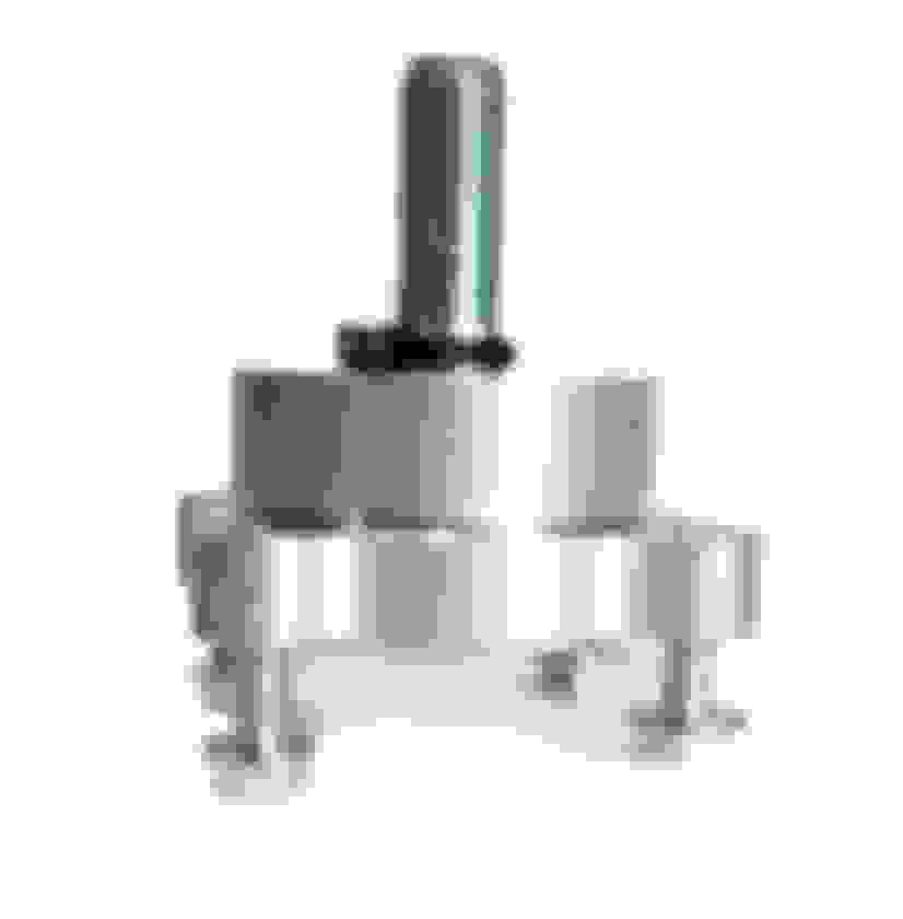
When you are installing the front three 13mm bolts which secure the timing cover to the new oil pan, recognize that we will be adding the trigger wheel sensing bracket to the front of the timing cover as is illustrated in the following picture. Illustration of trigger wheel sensor bracket mounted in it's proper position on the bottom front of the timing cover. There may be different versions of this bracket which look slightly different. Andrew has continued to improve and modify some of the kit hardware as he learns new lessons during his engine swaps. This is a picture of the trigger wheel mounting hardware. As shown here, Andrew includes all of the bolts necessary to complete the engine swap activities. This new piece replaces the bolt and washer that would normally secure the harmonic balance pully to the front of the crank shaft. During the original engine disassembly and removal, you want to make sure you retain the phonic/trigger wheel from the original engine and the magnetic induction coil pickup used to sense the wheel rotation. This information is used by the car to manage many engine and display operations. By retaining and installing these, all of the display information and fuel management controlled by the car computers work properly. I put this image in here because I thought the trigger wheel hole pattern was not aligned with the trigger wheel mounting hardware. At first glance, the hole layout appears to be symmetric... however, it isn't. You need to rotate this trigger wheel and possible flip it until you get it to properly line up with the kit trigger wheel adapter hardware. It will only fit one way. So, "do not" drill out new holes to "make it fit". This is a really bad idea. Fortunately, I came to the proper conclusions about this before I decided to drill holes myself. However, I did spend some time thinking about this before I got to the correct solution. View of the engine with new oil pan, trigger wheel sensor bracket and harmonic balance pulley properly installed. Again, this is not the oil pan on my car because I have borrowed this image from one of Andrews swap videos.
During the oil pan change process I thought I would be smart and replace the bottom bolt that required me to pull the harmonic balance pulley with a stud that would allow me to use a nut in it's place. So, that is what I did. The picture below is the outcome of that process and why I would recommend that you not head down this faulty path. I tried to be smart about this and made sure that the stud I used was shorter than the existing bolt. However, as you can see in the photo, once the harmonic balance pulley was reinstalled, it was a hairs width away from the new stud ( I obviously got the stud length a bit too long). Amateur mistake. But worse than this, after I proceeded to carefully grind off the extra length of the stud (right up to the face of the nut). I realized that the whole process was doomed from the start because there is not enough room to back the nut off and clear the back of the harmonic balance pulley. So, while I thought this was a good idea... it wasn't. Again amateur mistake. I should have measured this clearance before disassembly to ensure the proposed change could work. Picture of harmonic balance pulley after being reinstalled. As is clearly visible in this picture, the stud I used to replace the original bolt was very close to the balance pulley. To fix this clearance problem I carefully cutoff the end of the stud right at the face of the new nut with a cutoff wheel. It was apparent after the cutoff process that I still didn't have clearance to remove the offending nut. In addition to this, if I ever need to remove this stud, to get the oil pan out... I may have fun removing it. Guess I'll cross that bridge when I get to it. If I get there again, I will go back to the original bolt at this location. Lessons learned.
Thanks for the positive feedback r3mix. Andrew's videos are a huge assist to getting this swap done. However, there are always some things that sneak into the mix that you have to work through yourself. I'm trying to document both while pointing out the things that worked well and the bits I had trouble with. The target is to help other people that decide to go down this path. Much of this is information I would have liked to have when I started the process. With that said, a lot of the learning is driven home by the search, consolidation, and implementation of what you think you now know.
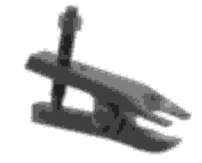
Time to move onto the front subframe modifications: I replaced the following components on the front subframe as shown in this photo, the wheel studs, the front rotors, and the brake calipers. Note: I think the RX8 came a couple different configurations of front rotor sizes 11.9" or the 12.7". I believe the 12.7" rotor came with the sport suspension. In many earlier automatic RX8 configurations the car came with the 11.9" rotors. You really don't want these on your car. The 2006 Automatic that I bought came with the 12.7" rotors which is what you need to use the Wilwood caliper in your swap. As a side note, the 2006 automatic car also came with the 6 port engine configuration (but the engine was limited to 7500 rpm in software. I think this was due to the reduced speed tolerance of the automatic transmission. There is no requirement to press out the front wheel bearings to replace the front wheel studs. The hub can be removed with four bolts and the bearing assembly comes with it. However, there is no requirement to remove the hub. Instead, I just pressed out the studs with a ball joint separator and the new studs can be pulled through the hub with a Lisle stud installer and a impact wrench. Also shown in this picture is the adapter bracket used to mount the new Wilwood superlite caliper to the existing wheel hub. While the original front upper control arm is shown in this picture, these were later replaced with a new set of upper control arms from Phase2motortrend. This is a photo of the ball joint separator tool I used to press the original studs out of the front wheel hubs. I purchased this from Harbor Freight and while some folks have had issues with theirs, this tool worked exactly as intended for my application. The wheel studs pressed out with no issues at all. This is a picture of the Lisle 22800 wheel stud installer. I purchased mine from Amazon. Again, I found this to work very nicely. I can't remember but I think I used some additional washers between this and the wheel hub to enable me to use the original wheel lugs to pull the extended length studs into the wheel hubs.
1. Changes to the location of the steering rack
2. Replacement of the steering tie rod hardware
3. Addition of a new front anti-sway bar with an adjusted position brackets
4. Removal of the original engine mounts
5. Removal of original engine mount welded alignment brackets
6. Loose installation of new LFX engine mounts
Relocation and adjustment of the steer rack assembly is provided in the following pictures. After removal of the existing steering rack assembly, the spacer supplied with the kit is attached to the existing steering rack mounting location. Note: The straight spacer is used on the drivers side of the front subframe. These bolts are torqued to 70 ftlbs. Similar spacer attached to the passenger side of the front subframe. Note: This spacer has a curved cutout which is necessary for clearance of the electronic power assist unit with is part of the steering assembly. Again, these bolts are torqued to 70 ftlbs. Also, you will need a thin wall socket to get down onto these bolt heads. Then the original steering rack is reinstalled on top of the new mounting brackets. The steering rack bolts are torqued down to 70 ftlbs. In this photo the steering tie rod end locking nuts have been slightly backed off and the tie rod has been removed. This photo shows installation of the new tie rod on the drivers side of the steering assembly. Similar image of the installed tie rod on the passenger side of the steering assembly. Passenger side tie rod installed into the knuckle. Note: The new tie rods supplied in the kit provide a number of different spacer configurations which allow some latitude to eliminate/minimize potential bump steer due to the relocation. Also, observe the orientation of the solid aluminum rod in the new tie rod. This section needs to be rotated so that the bent section is facing aft as shown in this picture. If it is facing forward, there is a good chance that it will rub against the inner wall of the wheel. So, make sure it is faced rearward.
The next set of picture illustrate the replacement of the anti-sway bar with the modified position provided by the kit spacer brackets.
Following removal of the original anti-sway bar. The new anti-sway bar positioning brackets are installed on the front frame at the original mounting locations. The mounting bolts are torqued to 50 ftlbs. Note the orientation of the new brackets. Similar installation of the new anti-sway bar bracket installed on the passenger side of the subframe. Again, these are torqued to 50ftlbs. This picture shows the new anti-sway bar installed to the new aluminum adapter plates. A couple things to notice, the C-clips and bushings from the original anti-sway bar are removed and used with this new anti-sway bar. As Andrew points out in his installation video, you want to make sure to center this sway bar prior to torquing down this sway bar with a torque of 50 ftlbs. I later found that if the car was on the lift with the suspension fully unloaded (full droop)... I had contact between the sway bar and the drive pulley for my ac compressor. After figuring out the issue, I was able to move the anti-sway bar over slightly which provided the clearance I needed. So, this is something you want to look out for during you installation process. I shared this with Andrew and he was not aware of anyone else experiencing this issue. Also, before reassembling the anti-sway bar, I applied some new thick/sticky lubricant to the bushing to bar interface. This will likely become a periodic maintenance item.
Next we can see the removal and replacement of the engine mounts.
The original RX8 hydraulically damped engine mounts are removed from each side of the front subframe. You don't want to try and pry these out of the car while the engine is in the chassis. If you get under the hydraulic bladder with anything that can out a stress concentration on the bladder. If can and may fail if you do... ask me how I know. Then you want to take an angle grinder with a cutoff wheel and remove the guide bracket welded to the existing subframe. Use the face of the grinding wheel to grind the bracket stubs to a flat surface for the new engine mounts. Similar picture showing removal of the passenger side guide bracket. Again, you need to use a grinding wheel to eliminate the excess metal left after bracket removal. After the surface has been flattened and the new engine mount fits nicely in the modified hardware. The exposed metal surfaced should be primed and painted with a reasonable quality automotive paint. Picture showing the passenger side poly engine mount (supplied in the swap kit) installed in the subframe. At this stage of the process, the engine mount bolts are left loose to enable easier installation of the LFX engine. Once the LFX engine is installed on the engine mounts, the engine mount bolts can be torqued down.
Pictures of my modified subframe partly through the modification process. Mostly front view of my subframe after installation of the steering assembly and new anti-sway bar. While I have removed the original engine mount guide brackets and ground down the surface, I have not primed and painted the surface or installed the new poly engine mounts. The people paying attention should notice that I have the aluminum section of the new tie rods facing forward in this photograph. You want to make sure you rotate these 180 degrees so they are facing aft. These must be facing aft to clear the interior surface of the wheel. Top down view of my subframe after installation of the steering assembly and new anti-sway bar. While I have removed the original engine mount guide brackets and ground down the surface, I have not primed and painted the surface or installed the new poly engine mounts. Again, people paying attention should notice that I have the aluminum section of the new tie rods facing forward in this photograph. You want to make sure you rotate these 180 degrees so they are facing aft. These must be facing aft to clear the interior surface of the wheel.
Have you received your PSS9s yet? I too am in the middle of a Keisler swap.
Yes. Note: I bought the kit from Andrew about 2 years ago now. So, I've completed the car and I'm currently driving it. I'm just getting around to documenting it for other people that might have an interest. The only thing I still need to get figured out is the air conditioning.
The original engine has obviously been removed. However you can also see that the inlet airbox, radiator and cooling fans have been removed. The battery box. and electrical control box have been removed from the front passenger side of the engine bay. The air pump assembly and it's control have been removed from the tower strut area on the passenger side of the engine bay. Finally, the wind shield washer fluid reservoir has been removed from the passenger side firewall. As can be seen in this picture, the front subframe was still in the car at the time of this photograph. However, it was removed before any additional modifications where made to the engine bay configuration
Slightly different viewing angle which allows you to see the Mazda standard clear plastic cover which blocks off the location hole for the clutch master cylinder (just to the right of the brake booster) when the car is configured as an automatic. This plug was removed and I acquired a used (clutch, brake, and accelerator) pedal set from Ebay for my swap to be able to install the new wilwood clutch master cylinder (supplied in the kit), and to swap out the original automatic brake pedal. Note: The original accelerator pedal will be replaced with a new Camaro accelerator pedal with all of the necessary position sensors. Additionally, there is a small adapter to allow the Camaro accelerator pedal to bolt directly in the original accelerator spot without additional modification. Both the Camaro accelerator and adapter are provided as part of the kit. Since the original clutch pedal support was found to be somewhat weak (it broke for many people in the original standard cars). I made sure that the clutch pedal I purchased from ebay had already been modified by welding additional support in the region that was known to break in the original cars.
Picture of many of the parts removed from the engine bay. Lower far right are the coolant hoses. Side those is the windshield washer reservoir. Above the hoses are the RX8 coil packs and plug wires, and some pulley belts. Above that is the battery box. To the left of those are the intake airbox hardware. Directly below the airbox are the airpump and electronic control box hardware. Most of the rest of the hardware are interior console, and trim hardware. Except for the spare tire kit, and the lower transmission tunnel/drive shaft protection brackets, the RX8 exhaust manifold before I reinstalled it and original coolant overflow reservoir. This is a parts breakdown of the RX8 air pump assembly. We really only need a few parts from this. Those include the air pump bracket 13-920, the resistor 18-831, and the rubber mounting hardware 13-331A, 13-343, 13-363, and 9973-0508 Location and illustration of the wind shield washer reservoir. Note: There appear to be multiple versions of this part so your part may look slightly different than this one. This part is removed to make room for the new engine coolant reservoir that is provided as a part of the LFX swap kit.
Note: At this point the heater hoses have been removed from the heater core tubes poking through the passenger side firewall. The high side AC refrigerant lines have been removed at the same location. The battery and oil coolant lines have been removed along with the oil coolers. But, the support beam that spans the width of the engine bay which provided attachments for the battery, oil cooler lines, and cooling fan electrical connection are still in place. No modifications have been made to the engine bay supports yet. You do have to spend a little time to release all of the retention tabs on the electrical cables that are routed into the control box and you will need to remove the cooling ducts which route cool inlet air into the electronic control box housing. I did have to modified the cooling air supply ducts before I put this all back together due to changes in the radiator mounting location.
The next order of business was to clean up the engine compartment even further and prepare the compartment for installation of the LFX engine hardware. Again, I will walk through a combination of photographs from the swap videos and the resulting outcome in my specific swap actions. In my case, I removed the insulation/sound blanket which covers much of the engine compartment, and cleaned up the engine bay. However, even though this was not absolutely required, I removed the brake power booster and brake master cylinder for two reasons. The first was to give me easier access to the firewall area around the clutch master cylinder access hole through the firewall. The second was that I needed to remove the larger brake pedal hardware from under the dash anyway to install the alternative brake pedal for the new six speed manual Camaro transmission. Additionally, I elected to temporarily remove the brake ABS/Stability control module. Note: The RX8 has different configurations of brake modules and you will need to send some photos to Andrew early in the process so he can make sure to provide the proper modified mounting bracket for the brake module you will be moving. The reason I pulled this brake module was that it gave me a lot more space to remove the drivers side subframe mounting/locating posts and opened up space to modify the existing mounting pad normally underneath the brake module. The following photos illustrate the changes to the engine compartment:
This photo shows the an overall view of the modified engine compartment after much of the charges had been made. It is obvious here that the insulation/sound cover has been removed. The engine compartment cleaned up nicely as shown in this photo. Additionally, you can see that the brake power booster, brake master cylinder and antilock/traction control brake system module have been removed. In my case, since I was converting from the six speed automatic RX8 transmission to a six speed manual manual transmission I needed to run a new electrical connection from the ignition switch, through the clutch lockout switch, then out through the firewall and to the fuse block in the lower right of this photo. I drilled a small hole just barely large enough to route this new wire into the lower region of the fuse panel. This wire was then used to provide a proper signal to the starter solenoid relay to crank the starter. When going through the firewall, I used the existing grommet and wiring that was already routed through the firewall to route this new wire. Then I tied it off to the existing wiring loom with periodic zip ties to keep it from moving around. Whether you have the automatic or manual transmission version of the RX8, you will get a new Wilwood clutch master cylinder as a part of the swap kit. This part is required because the Camaro six speed manual transmission clutch throwout bearing actuator requires more hydraulic force than the RX8 clutch master cylinder can manage. The new Wilwood clutch master cylinder provides the added hydraulic force required. However, the Wilwood master cylinder requires a slightly larger access hole to fit through the firewall. So, you will need to open up the existing access hole about 1/8 of an inch. This photo shows Andrew opening up the hole. This photo shows the clutch master cylinder access hole in my car after it has been opened up. As you can see, when I was opening up this hole, it was easy for the grinding bit to walk out of the hole and scrape the paint. I suggest grinding a little bit at a time and test fitting the new Wilwood clutch master cylinder until it slides cleanly through the widened hole. Then, debur the modified hole. I lightly sanded the area, cleaned it and applied a coat of primer and red paint to match the existing body paint. I did not go crazy trying to match up the paint, I just picked something that was close... because most if not all of this region is hidden by other hardware once the installation of all hardware has been completed. I did use a high temperature paint... even though it was probably not necessary. Before installing the clutch master cylinder, you can loosely assemble the clutch pedal assembly to the clutch master cylinder outside of the car. This allows you to adjust the actuator rod to the proper length so that the mounting pin will easily slide through the mounting hole when it is under the dash. Once the clutch actuator rod length has been set to the correct length, you can disassemble the clutch pedal bracket from the clutch master cylinder to prepare it for installation in the car. There is not a lot of room under the dash and this makes installation of the brake pedal easier after the clutch master cylinder has been installed through the firewall. The next order of business is to remove the subframe mounting/alignment pins from the engine compartment chassis. You need to do this to enable movement of the subframe while it is in close proximity to the chassis during reinstallation of the subframe with the LFX engine in it. Since these subframe mounting pins are tack welded to the chassis, you need to lightly grind down the welded region. You want to remove most of the weld but you don't want to cut into the chassis structure. Once each of the subframe mounting bolt welds have been ground down. You can use a impact wrench to break these bolts free of the chassis. I used a old corded electric impact wrench for this and the welds broke free without much resistance. Note: These bolts are an interesting design. They have two threaded sections. The threads closest to the bolt head are used to anchor the bolts to the internal threads in the chassis (locate the mounting bolts rigidly to the chassis), while the second set of threads push through the bottom of the chassis and provide the alignment and mounting location for the front subframe.
This picture shows the holes which result from removal of the drivers side subframe mounting/alignment pins which normally reside below the ABS module. Again, after lightly sanding and cleaning these holes, I applied a primer and paint coating to this region before I began the installation. As shown in this photo, I did tape off all of the open brake lines to minimize the risk of getting crude into these lines while they were open. The large connector in the bottom of the picture is the electrical connector which attaches to the ABS/TC brake control module. Also, if you look through the power booster access hole, the tan metal tab you can see on the inside of the firewall it the retention feature you need to work the brake mounting bracket off of to remove it from inside of the car. Note: I needed to do this because I was switching from the automatic transmission to the manual transmission. If you already have the manual transmission with the narrow brake pedal, I would not remove the brake pedal or the brake power booster. In you do remove the brake pedal, you will likely be required to purchase a new brake position indicator switch. The car must learn the proper position after the pedal is swapped and this is apparently something that can only happen once. So, I bought a new switch and the relearn process worked automatically without incident. I did not spend any additional time trying to figure out if there was a way to reset the switch so I wouldn't have to buy a new one. It wasn't expensive enough to make it worth my time to do all that additional work.
The it was time to remove the battery mounting cross brace. Note: In the standard RX8 configuration, this brace provides mounting points for the battery box, the fan power lines, a number of grounding posts, and mounting locations for the oil cooler lines. This photo shows marking the top location to cut the battery support brace. This photo shows the target cut line for the top of the battery support brace on the drivers side of the car. Note: You want to walk softly here, you don't want to cut into the chassis frame when making this cut. While not shown here, I similar process is used to mark the bottom of this brace prior to using a angle grinder with a cutoff wheel to remove the brace. Here is a photo of my car after the cut and removal of the brace. This is the drivers side of the car which should be obvious due to the appearance of the bottom side of the fuse panel in the top of the half of the picture. Again, after this brace was removed, I lightly sanded the affected area, primed it, and applied a coat of read paint to protect the cut surface from future rust/corrosion. This photo shows the other side of the engine compartment after removal of the battery support brace. Again, you want to be careful not to cut into the frame rail. This is the passenger side of the engine compartment. The rubber coated tube in this photo is the remaining AC line between the firewall and the expansion valve mounted to the front rail of the engine compartment.
The we needed to clearance the brake module mounting pad. Things get tight when installing the LFX and front subframe back into the chassis and this clearancing is necessary to thread the needle during the reinstallation process.
This photo shows a top view of the target cut line for the top of the brake module mounting bracket. Not shown is the corresponding vertical cut line that is aligned with the vertical metal overlap region of the brake module mounting bracket. This provides a clear target cut line for the vertical cut. View the angle grinder making the top cut of the brake module mounting bracket at the target cut line with a cutoff wheel. This photo illustrates the dominate changes made to the engine compartment region prior to reinstallation of the subframe with the LFX engine installed. Notice the removal of the four subframe mounting/alignment posts, removal of the battery support brace across the engine bay, and trimming of the top left corner of the brake module mounting bracket. The gold rod you can see to the left of the brake module mounting bracket is the steering shaft. I later removed this to get it out of the way during the engine installation. While this was not required, I felt better getting it out of the way. Note: I wish I had taken better pictures before I removed it as there were some questions about the location of the plastic sleeve on this steering shaft. Fortunately, I was able to find pictures of the part breakdown for this assembly to make sure I reinstalled all the bits correctly.
Andrew's videos did a great job of guiding me through this process and demonstrated the actual process. This information is hugely informative and gives an inexperienced engine swapper the confidence necessary to get the job done.
Respect! One of the finest adverage guy documentations of a build I have ever seen.
Are you driving it yet? Any further engine mods such as intake porting/spacer, true cold air intake etc? I am still contemplating this swap myself, I would like just a little more wheel hp. Do you think there is room for an overkill centrifugal supercharger mount?
Thanks for the kind words Olddragger. I've been feeling a bit guilty for not getting back to this. So, in the next couple days I will try to get back to the rest of the swap story.
In answer to your questions:
1. Am I driving it yet? Yes. I've been driving it since the beginning of December... I've competed in 5 autoX events (one per month since Dec). I have also put about 2k miles on it running around the Phoenix area. The car is running well and I've been having a good time with it (it has performed consistently without issues - outside of some very minor oil leaks that were fixed with some mild wrenching).
2. Any engine mods? Kind of, while I had the engine out I cleaned up all of the intake ports and valves. I elected to purchase the laminator (by Jacfab) insert to improve the inlet airflow and removed the plastic airdam/swirler at the front of the intake manifold just down stream of the throttle body. If the video is to be believed, those changes to the inlet should allow for 16-17% increase in inlet airflow. Have I formally tested with and without the changes (No). I provided a link/copy of the video from Jacfab that describes this modification earlier in this engine swap story. As a part of the track package I bought from Andrew, I got a modified intake that routes the intake filter out in front of and above the radiator. So, this is probably as close to a cold air intake as I can get. One down side of this change is that to change/clean the intake air filter I now probably need to remove the front bumper. I have high flow cats on the exhaust down pipes and a fairly low restriction exhaust system. My car has not been on a dyno yet so I cann't offer up any performance plots to show you where it is performing. I did not buy the intake spacer to improve airflow into the head... mostly because there is likely not enough space to clear the inside of the hood against the top of the plastic air intake.
3. Do I think their is room for an overkill centrifugal supercharger mount? I've included the A/C compressor because it is desirable to retain air conditioning here in Phoenix. If you elected not to do that, I think with the proper design and effort, it might be possible to squeeze the supercharger in. Note: I don't think this will be a simple task and I haven't really looked at the dimensions for that supercharger system. As an aside, I seem to recall some comments about the transmission and differential not having a lot of extra margin beyond the original design power levels. I seem to recall that 350-400 wheel Hp is about the limit of the drive train. However, I haven't experienced those limits myself.
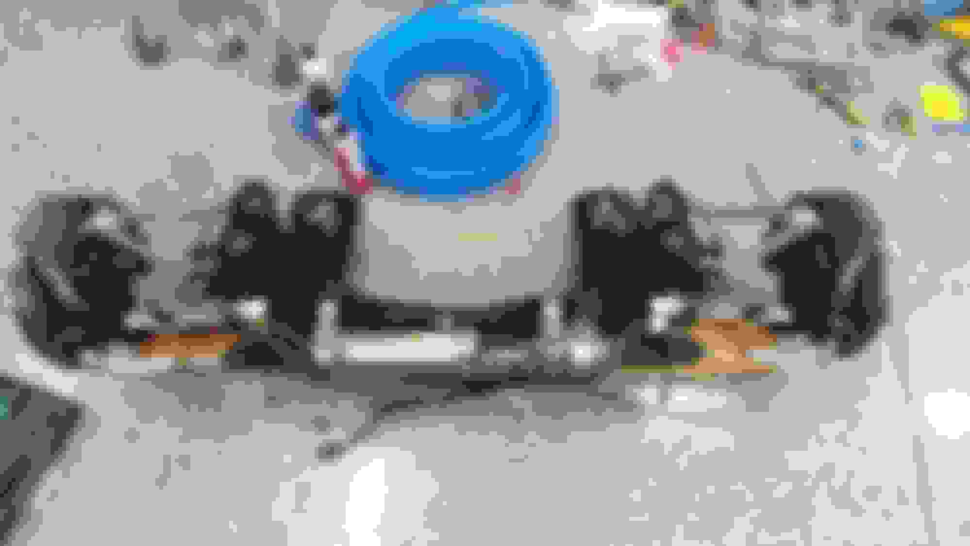
Great write up. Here is a picture of the Ford 8.8 Diff installed in the rear subframe since Andrew has since gone to this configuration. Also pictured are the latest half shafts.
Hi 1StopJeff and thanks for the nice words. I was aware of the 8.8 diff change Andrew has prepared. I provided a link to the thread that RX8club had prepared that provides a link to the video Andrew prepared for this newer diff integration. I've repeated that link here https://www.rx8club.com/non-rotary-s...ion-kit-274355
I don't recall seeing the new half shafts in the past though. I really like the look of the new half shafts. Thanks for providing these pictures.
The half shafts are hot off the press. I had my car done but had to wait over a month for the new half shafts from the new supplier. They arrived last week 5/2. Andrew said they are good for 1000HP! 😳