When you click on links to various merchants on this site and make a purchase, this can result in this site earning a commission. Affiliate programs and affiliations include, but are not limited to, the eBay Partner Network.
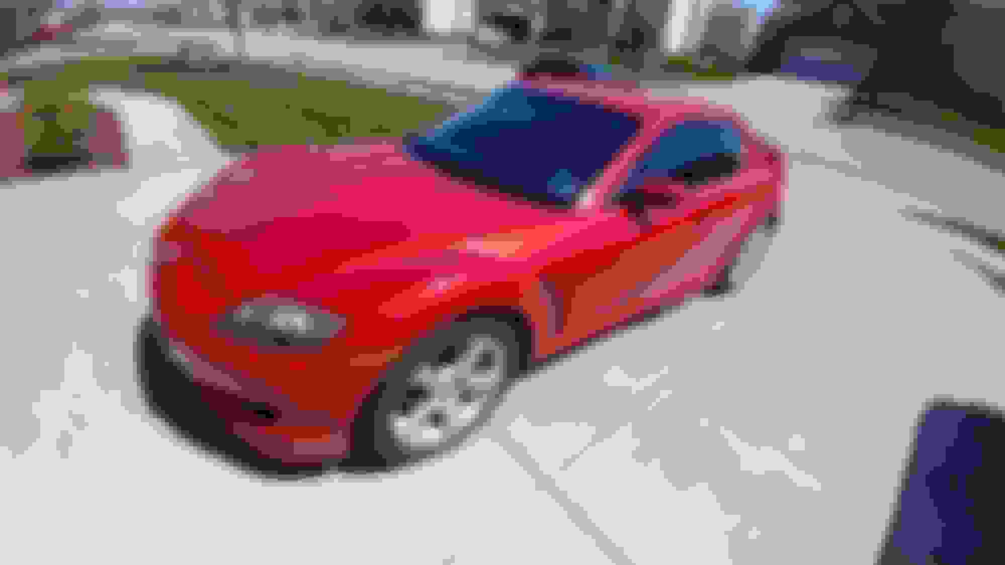
To give you the punch line at the beginning, yes, this is another LFX swapped RX8 story (based on the comprehensive and detailed kit designed and marketed by Andrew at Keisler Automation). I hope to provide you with some of the behind the curtain stories about what went well and what didn't and the steps I took to get to this stage of the story. I'll point out the issues I had, the decisions I made, including the mistakes and learning opportunities. This was my first foray into this level of car modification without a serious background in the field. So, plenty of learning experiences. With that said, here are a couple of pictures of the car as it sits today to grease the skids. 2006 RX-8 Started out life as a 6Spd Automatic. Louvers are part of the Keisler Automation kit. Most people would likely rotate the louvers forward. I haven't decided yet whether I will or not. The new engine bay with a 3.6liter LFX extracted from a 2015 Cadillac XTS with 37k miles. It's a snug fit... but it does look nice in the engine bay Yes, as is obvious in these photos, we removed the hood interior sound proofing and cutout the interior of the aluminum hood. This was done to clear the front top of the LFX intake. However, we got a bit more aggressive and removed a large part of the interior of the hood. However, with the louvers, I can now exhaust more heat from the engine compartment and get better airflow through the inclined radiator.
Before I get too far into this, my experiences with the RX8 started in Dec of 2003 when I purchased a brand new 6spd manual RX8 and immediately joined the rotary car club in Arizona. I participated in regular monthly car club mountain drives and daily drove the car until I moved from AZ to Indy in 2007. During my time in AZ, the rotary club hosted an annual caravan out to Seven Stock where we joined up with many rotary enthusiasts to share stories and experiences with this unique family of cars.
The new 2004 RX8 parked at the top of south mountain in Phoenix Az. My original 2004 RX8 sharing the tarmac with some of it's friends from the Rotary car club.
Fast forward to July of 2018,when sold my 2004 RX8 with 85k miles on an original engine that was still running strong. Here are pictures of the car when I sold it in Indy.
2004 RX8 with 85k Miles on the original engine which was still running well. Car was never in an accident and never left me stranded. Headlight covers were getting tired and the typical dashboard cracks above the glove-box were it's biggest problems.
After moving back to AZ in 2018 I was toying with the idea of building a kit car and had focused in on one of the factory five options with my eyes on the 818. However, I thought as a first entry into this level of automotive work, that might be too big an effort. In the mean time, I had purchased a 2015 BMW M4 and was teaching myself to drive it in the local autocross competitions. While it's a great car, I found the throttle difficult to modulate and tended to overdrive it aggressively. Even with decent tires and the double clutch transmission I found myself wrestling with the car. It felt heavy with more under-steer than I wanted and was turning out to be a moderately expensive car to drive aggressively. During this time I bumped into TrackCarObsession's youtube series on the RX8 LFX swap which pointed me to Andrew's website (https://www.keislerautomation.com). After reading his web site and thinking about the information he provided, I realized that the RX-8 was 600 lbs lighter with a shorter wheel-base than the M4. It sits lower in the front with improved visibility and has a fantastic (my opinion) suspension underneath it. So off I went looking for an RX8 donor car that I could start with. In Jan 2020 I found a 2006 6Spd Automatic RX8 with the original engine, transmission, with 67k miles on it. The car was running and moderately healthy without any accidents. In addition to that, the car has lived it's entire life here in the Phoenix AZ area. It was a base model car with cloth seats and no sunroof which was exactly what I was looking for. The cloth seats wear better, are a lot lighter, and don't include all the motor driven adjustments. The standard roof provides me with above 3/4-1" extra head clearance for when I'm driving with a helmet on.
The car has a few blemishes but the undercarriage and interior were in good shape and the previous owner was a non-smoker ( a necessary requirement ). Here is a picture of the engine bay and console view showing that everything was still original. Nice to see an original unchanged engine bay with all the standard covers in place. Not only that I got a copy of all of the maintenance records for this one owner car who had in maintained by the dealer. Car was driven lightly by the owner with only 67k miles over the first 14 years of it's life.
Finally, since the car was garaged and lived here in AZ, there was little rust on all of the undercarriage hardware and the paint while not great was at least in good shape.
Prior to starting the disassembly, I listed the engine, transmission, differential, and exhaust for sale. I did this to allow new potential owners the opportunity to drive the car and experience the current state of the engine. I had compression measurements from the dealer which showed that the engine was still acceptable but was showing some of it's age. In fairly short order I had contacts from two individuals interested in the engine and exhaust systems respectively. After driving the car and experiencing the engine condition, I sold the engine to an individual from Scottsdale. Additionally, the individual interested in the exhaust was really focused on the Cat and wanted some photos of that before they came over to look themselves. So over the next week I removed the exhaust, transmission, and engine in that order. I had a hard time breaking the bolts free at the exhaust flange to Cat transition fitting and ended up removing the exhaust manifold from the engine to make this process easier. However, that was still a difficult process because you need to be able to remove the passenger side engine mount to allow the exhaust manifold to clear. In the process of trying to pry the motor mount out... I ruptured the mount bladder which destroyed the mount and dumped the damping fluid all over everything. So, word to the wise, be careful with these fluid filled motor mount bladders. If you get aggressive with them, they will tear and you'll be buying another one if you need them. Fortunately, I didn't need the one I destroyed.
Here are some pictures of the disassembly process. At this stage I had place the car on jack stands both front and rear and removed all the wheels and tires to give me some room to move about underneath the car.
Here is the original Cat after 67k miles. The flat spot on the bottom shows that it was scrubbed against something hard at least once in it's lifetime. However, not to bad for the wear. The person interested in the Cat wanted a picture of the active elements in the core. This is my photograph of that element showing that it is in pretty good shape. I took off the exhaust from the midpipe back. While I sold the entire exhaust for 350 which I thought was a fair/ maybe low price. I found myself wishing that I had kept the muffler and exhaust tips for use on the new exhaust. It would have been cheaper to have kept this hardware. However, this muffler is quite heavy.
Next I removed the transmission with a trans-jack and my son. It was touch and go doing this. I hadn't really given myself enough clearance to pull the transmission out from under the car. So, word to the wise, extend the jack stands far enough that you have adequate ground clearance. Removal of the powerplant frame and drive shaft/propellor was fairly straightforward. Additionally, getting the transmission was fairly easy as long as you had all the extensions to get to the transmission housing bolts. Also, in some cases, it was easier to reach bolts from the engine bay rather than underneath the car. Off course you need to remove the starter and the torque converter bolts before you pull the transmission. Additionally, you will need to remove the shifter linkage in the drivers compartment. In my case, I had every intention to convert the car to a Camaro 6 spd manual transmission so much of the car interior was removed too.
Car on jack stands prior to engine removal. Bumper, radiator, cooling fans removed. Rather than cut anything, I took my time to remove all of the fittings and connectors at the proper locations. I wasn't in a hurry and over couple of days working part time I was able to get to the point that the engine was ready to be removed. This side view shows that the battery and battery box, body control module, steering control module, and engine control module along with the mounting box have been disconnected and removed from the engine bay.
At this point I still needed to disconnect the oil cooler lines. As it turns out, it probably would have been beneficial to have removed the anti-lock brake system prior to engine removal just to get it out of the way. However, we removed the engine without doing that. Later I removed the anti-lock brake module anyway to clearance the bracket it mounts to. So it might have been better to do that first.
At this point I came in with the engine hoist and attached it to the engine. With the help of the people that were buying the engine, we pulled the engine out of the engine bay through the top with the engine hoist. Knowing a bit more about the process now, it probably would have been a lot faster and easier to have put the car on my MaxJax lift and removed the front subframe, engine, and transmission by lifting the car off the top of that assembly. With that said, the engine by itself comes out pretty easily with the engine hoist. Thanking back... I didn't have the lift yet so it wasn't available for the engine removal. Six port Renisis engine after removal from the car. I was able to remove this without having to remove the intake. At this point I have loosely reattached the exhaust manifold so we wouldn't misplace any of the hardware. As you can see, the engine side oil cooler lines were still attached. Engine bay following engine removal. Note: I had the AC system discharged by a local auto repair center prior to listing the car for sale. So, I was able to break into the AC lines without releasing anything into the atmosphere. At this point the engine bay looks big. However, it fills up pretty quickly when you stuffing a 3.6 L V6 into it.
Next, the steering assembly was removed from the front subframe... I could have waited to remove this but I removed the steering linkage prior to removing the front subframe.
Radiator and cooling fan assembly, AC compressor and associated AC refrigerant lines, electric power assisted steering gear and dual oil cooler heat-exchangers with associated oil lines. Front subframe assembly with front coilovers and steering assembly removed. Note: To remove the subframe it was necessary to disconnect the brake lines in the wheel wells and it was convenient to remove all of the wheel well covers from the car. Because I was building up a large number of bolts and fittings, I started putting everything I could attach back in the holes they came out of and everything else went into labeled baggies that were stored in the same location as the parts they went with. This helped a lot during the reassembly process even though many parts were changed.
While not shown in these pictures the stock front coilovers were removed from the front subframe and the tower struts during this disassembly process.
Next I removed the rear shocks, disconnected the rear brake lines and detached them from the rear subframe housing. This required removal of the truck finish covers and wheel well liners. In the process of removing the wheels from the rear wheel hubs, I broke one of the wheel studs. Rather than leaving it like this I decided to replace all of the wheel studs with extended length ARP studs. Once the brake and rear coilover hardware were removed/disconnected. I removed the rear subframe from the car with the differential intact. However, before I took pictures, I removed the differential from the subframe.
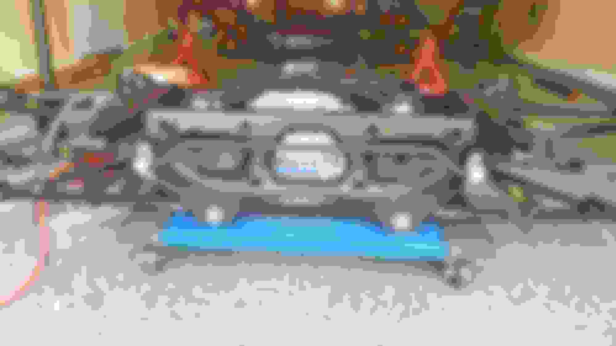
View of the rear subframe forward looking aft. All the suspension linkages have remained intact at this point. But the differential and the half shafts have been removed. View of rear subframe aft looking forward. Thinking back, I did have to disconnect some of the suspension linkage in order to remove the half shafts prior to removing the differential. Also, I bought four of these 1000 lb roll around carts that you see in these pictures. These were great for moving engines, transmissions, and front and rear subframes easily and precisely. For 20 bucks a piece at Harbor Freight they are hard to beat.
Very clean jealous of how little rust it has Im sure it was a breeze to get most bolts out
Lots of work but Im sure you will be another happy customer he has a good reputation and stands behind his work
I havea good friend who has been racing this setup for 3 seasons now and done very well with little to no issues
You are correct... one of the real advantages of living in AZ is the fact that car undercarriages don't get consumed by rust and as a result most bolts and nuts are painless to remove. I still elected to use FreeAll penetrating oil prior to most of the disassembly. With that said, the car came apart cleanly with minor sacrificial hardware. Additionally, the subframes cleaned up nicely with some warm soapy water and a few rags. Even the paint was in pretty good shape. Definitely feel fortunate for that. Watching some of Andrews many swap videos I was shocked at the rust on the cars coming out of the rust belt.
As I pointed out before, while removing the rear wheels and tires, I snapped one of the wheel studs. On this car that creates a minor issue... the only way to replace the rear wheel studs is the press the wheel hubs out of the rear knuckles which destroys the wheel bearings. However, this gave me a good reason to replace the existing wheel studs which were of questionable health with new ARP studs. I went with the ARP-100-7708 studs which included a longer threaded length and decided to go with a set of Gorilla Automotive 45038BC-20 Black 12mmx1.50 Forged Steel lug nuts.
It's helpful to have a reasonable manual to do this type of work... In my case I acquired a electronic copy of the Mazda Service Manual which provides assembly/disassembly pictures like this (which include the recommended torque specifications). So I removed the knuckles from the rear subframe to replace the studs and wheel bearings.
This is an example of the diagrams in the Mazda service manual I had access to. As stated, it provides an illustration of how each of the parts come apart and go back together and identifies all assembly torque levels for each part. With that said, youtube has become a wonderful resource for people that haven't done this type of work before. Of course critical thinking is required to filter through the chaff while retaining the wheat. When pressing out hardware... 1) You need a blank that is the right size (matched to the part your pressing out) and 2) you need to be able the support the stationary hardware while limiting residual damage. This take some experimentation... but after some thought and jiggling, rotating, balancing, and supporting the axle hub is pressed out of the knuckle. This brings with it the center race of the wheel bearing. Note: The C-clip can't be removed as it is trapped by the hub. As a result, the wheel bearing is destroyed during this process. Additionally, you need to remove the center race from the hub shaft and the main bearing hardware from the knuckle with additional press operations. Different size blanks are needed for each of these operations. Closeup view of the wheel hub. Note the rust buildup on the spline. This came back to bite me later. After the wheel hub was removed I pressed out each of the wheel studs. and installed the ARP studs after cleaning the hub surfaces. I should have spent some time cleaning up the hub internal splines at this time. Later this would cost me. Wheel side view of the reassembled wheel hub and knuckle assembly. I tried to clean up most of this hardware before it went back together. I wasn't working to a clock and had the time to try to clean things up. While cleaning the dust shields, I also did my best to return them to a round condition and removed the superficial dents and damage caused by my inexperienced press operations. This is the back side of the wheel hub and knuckle assembly. Note that the bearing is pressed fully back into the knuckle first using the outer bearing contact surface with full support across the bearing. The C-clip is installed. Then the back of the bearing is supported as the hub is pressed back in.
Note: I worked on one side of the subframe at a time so I would have an unmodified example of how things were originally configured to use as an example if/when there were questions during reassembly.
So, now the screw-up. When reassembling the axle into the newly installed knuckle and axle hub... I couldn't get the axle to cleanly slide into the splined joint. I tried a half a dozen times to make this work, rotating the hub assembly to clock the spline links... but it wouldn't go together. So, being a newby at this and assuming that bigger is better... I proceeded to try and force the two parts together with the help of a mildly persuasive 2 lb mallet. Yes, you've guessed right, after thinking about what I'd done (which wasn't really successful) I went out and rotated the wheel hub to find that I had completely trashed my new bearing.
After ordering a new bearing and repeating the pressing operations a second time... I carefully took a micro file and cleaned up the splines on the axle and the hub. Surprise, surprise once cleaned up, I could easily push the axle spline through the wheel hub while still having positive engagement of the spline surface. (Moral: Might doesn't always make right).
The wheel bearings I used in my rear wheel hubs were National (511039) purchased from RockAuto. As I was comparing these to the wheel bearings in my car I found that they had the exact same marking on the observable faces. I installed the bearings oriented in the same direction as the originals came out.
Replacing the differential was one of the next tasks. Andrew provides a nice example video illustrating how to complete this operation as a part of his LFX swap package. In my case, I wasn't too worried about trying to minimize costs and I wanted to end up with a car I could drive aggressively. So, I purchased Andrew's Total Swap Kit, the track package, the part 1 & 2 stainless steel exhaust with Cats, the AC line package (because it's hot in AZ), the Wilwood superlite front brake calipers, his fairly comprehensive LFX swap disassembly and reassembly videos and a set of Bilstein B16 PSS9 coilovers. This was a big ticket, but it's also a huge kick start for me to make this swap happen. Later, after trading some emails with Andrew I also chose to his newer baffled oil pan (which reduces the chance of oil starvation when exposed to long duration high G maneuvers during track driving). Original RX8 differential, half shafts, propeller/drive shaft, and power plant frame after removal from the car. After a request from Andrew, I cut the half shafts apart with a cutoff wheel and shipped them back to him for conversion to a hybrid drive shaft configuration (GM splines at the differential and Mazda splines at the wheel hub). I acquired a 2015 Camaro Carrier Assembly/Differential (3.27 Gear Set) from LKQ with 80k miles on it (would have liked less - but it's what I found). Based on Andrews instructions I drilled out the drivers side mount bushing rubber section and removed it. Then I removed the existing bushing sleeve by hack sawing through 90% of the sleeve and then persuading it to leave with a punch and a mallet. As you can see the sleeve looks a bit worse for the wear. Here is where you can have some fun with a mallet/hammer.
I also replaced the rear axle shaft seals on both sides of the differential with GM Genuine Part Number 291-338 (purchased from RockAuto) prior to assembly into the rear subframe.
As shown here, the normal passenger side diff mount has been removed. Those of you that are detail oriented will notice additional cut marks in this section of the mount. So, here I'll suggest... measure twice and cut once. I thought I had aligned my cut properly only to realize I was not quite in the right place. Fortunately, no-one notices this faux pas. So don't spread it around. Then I added the poly bushings provided in Andrews kit. The pins on the aluminum bar extending from the left mount provide the alignment for the holes that you need to drill through the front of the subframe. With this configuration it would be hard to screw this up. It's a well designed process. This picture shows the mounting of the front of the Diff to the rear subframe after holes have been drilled through the subframe. The alignment pins and aluminum cover plate make it easy to get this alignment correct. Note: I think the Andrew has modified his kit to potentially use an alternative stronger differential which has a different mount configuration. However, it looks equally straightforward in terms of installation work. Here you can see m first cut error. I became worried that I would cut into the wall of the diff forward snout. Fortunately this mistake is just a shoulder shrug. Top down view of the diff mounted in the subframe. In this image you can see the new diff rear cover (provided in the kit) which ties right into the Mazda diff rear mounts. Additionally, you can see the front mount fixed to the front of the subframe. This fit like a glove. If you didn't know better, it would look like it is original equipment hardware (minus my weight saving efforts).
.
Here is a final picture of the Diff from the rear of the subframe. Note: I thought about changing out the diff gear set before I put it in the car. However, when I looked at speed versus engine rpm for each gear, I decided this was a pretty good fit for the autocross driving I do. In most cases I can drive in 1st and 2nd for an entire autocross run. If I switch to the 3.45 or 3.91 gear set, I will definitely be required to make additional gear shifts at various stages of the autocross courses we run. If / when i migrate to road track racing, I will likely revisit this option. The subframe has been slightly cleaned and the billet aluminum diff rear cover with nice heat sink fins dresses up the diff nicely. Again these roller carts were great to hold and move these subframes around easily.
Just added a quick cross link here: TeamRX8 has pointed out that Andrew has developed another differential option for this car. If your interested you might look here https://www.rx8club.com/non-rotary-s...ion-kit-274355
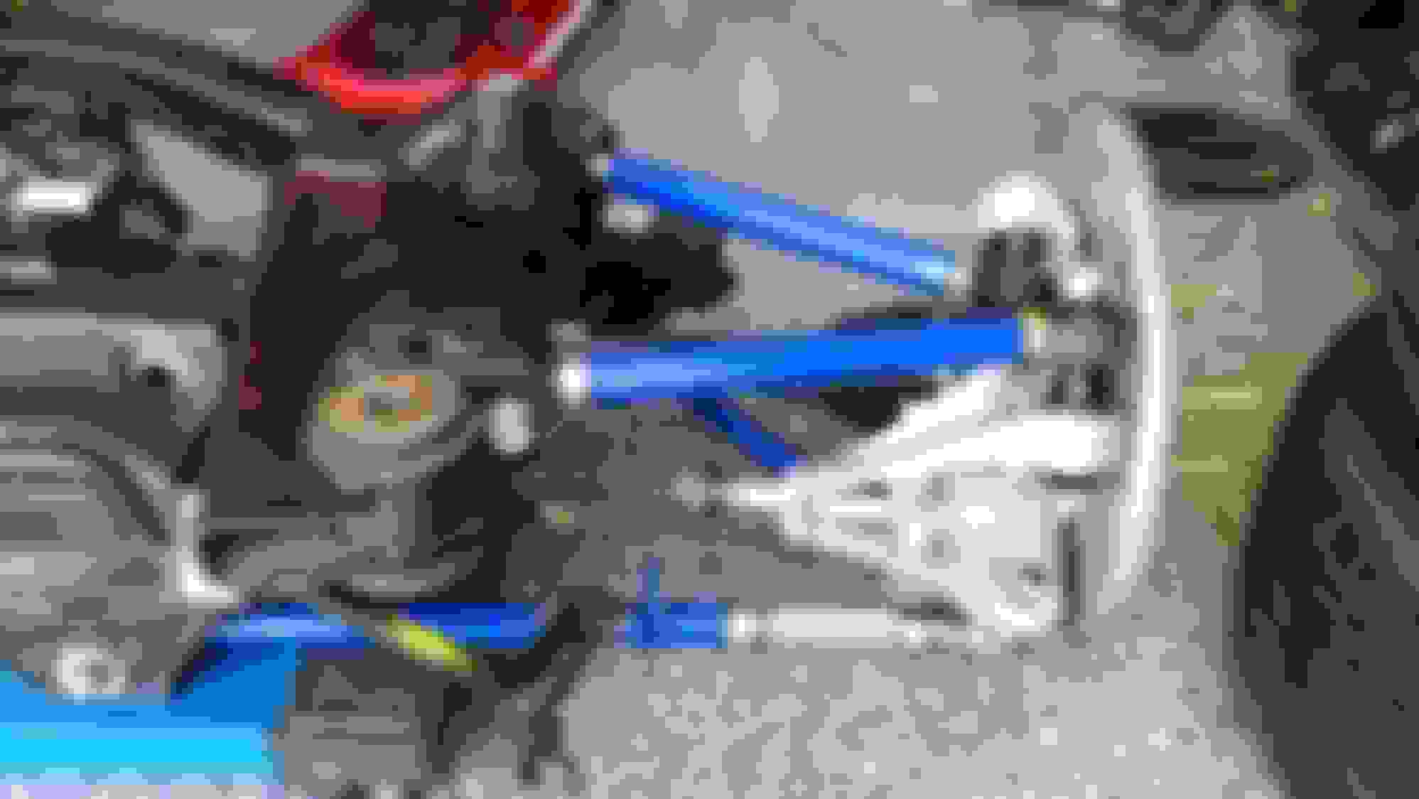
At this point I elected to replace the rear upper and lower control arms with spherical bearing adjustable control arms. At Andrew's suggestion I looked at Phase 2 Motortrend Inc who makes the control arms shown here. This gave me a lot more control over toe and camber for the rear suspension and allows a wider range of ride height adjustment while keeping wheel alignment in a reasonable range. I know that some people feel that the RX8 suspension is very good stock and I tend to agree with this. However, I wanted to see how the car behaved with some of the remaining compliance removed. Those of you who have been paying attention will also notice that I have not replaced to subframe mount bushings. I didn't want to wrestle with these at this stage of the build and ended up assembling the rear frame back into the car without swapping those out. I do have a set of poly bushings that I could install if I ever decide to pull the rear subframe again. Right now however, I'm not experienced enough to say that I really need them. I need to get more experience driving fast before I make a decision to change the current configuration. I will say that the spherical bearing control arms with the Bilsteins at medium ride height with max stiffness on compression and rebound is a pretty harsh ride on the street. I like it on he autocross track but need to try a variety of other options to decide what works best for me. In these photos you can see the modified/hybrid half shafts installed between the diff and the wheel hub. Later, I also purchased a set of front and rear spherical bearing anti-sway bar end links. When putting this hardware together I was no longer able to include the headlight leveling sensors. This really isn't a problem for me in AZ. It just points the head lights toward the bottom of the forward field of view which is adequate.
Hey, That is a very nicely documented process of the Keisler conversion. I appreciate that you took the time to document all this. Please keep it coming. ;-)
Thanks for the feedback. My plan is to continue through my history up to the car as it currently exists today. However, I haven't always taken all of the photos I should have. I will try to insert other photos and information where I can to supplement the photos I've taken. This will likely take a few weeks of nibbling away at the history. I'm glad that your finding it useful/entertaining.
Once I had the rear subframe back together, it was time to install it back in the car. To complete this process, a friend and I balanced the subframe assembly on my low profile hydraulic jack with a piece of 2x8 sandwiched between the diff and the jack lift arm. We then supported one side to hold the assembly mostly level and slowly raised the assembly with the jack.
Side note: I think I had removed the original RX8 coilovers, disassembled them to extract the top hat assembly, cleaned up the bits I was going to use and installed the cleaned tophats the Bilstein B16 Coilover cores. Prior to purchasing the Bilsteins I toyed with the thought of buying the Penske suspension package. While I may decide my purchase was short sighted, at the time I wasn't ready to pay the higher price (more than double the Bilstein price) and wait for a possibly extended period of time to acquire the Penske package. I recognize that the Penske suspension in a real upgrade over the Bilstein system. However, since I am a casual autocrosser, who is just out to have fun on the weekends, I didn't think I was experienced enough to take advantage of the Penske suspension.
As we raised the subframe, we moved and aligned the subframe with the chassis subframe alignment/mounting pins. Those alignment pins do a pretty good job of helping you reinstall the subframe in the correct location. There was a bit of jiggling and nudging to get the subframe to the right position... then some extra manual lifting to get all the pins engaged and allow the subframe to slide smoothly up to make contact with the chassis. Once the subframe was in complete but soft contact with the chassis, we verified that all of the subframe mounting bolt holes were centered. Once satisfied, we installed the mounting hardware, washers, bolts and nuts depending on the location. All of the mounting hardware was installed with blue loctite and then torqued to the Mazda service manual torque spec.
I'm a bit disappointed that I didn't take more pictures of this process to help illustrate the process. The following is the only picture that I have... which shows the rear drivers side wheel well looking across the underside of the chassis after the subframe was removed but before the original coilover assembly was removed Rear suspension removed (driver's side wheel well viewing across chassis). As you can see, there are four subframe alignment pins (two on each side). As shown in this photo, we reinstalled the mounting hardware loosely on the pins they were removed from to reduce confusion about where hardware goes during reassembly. While not visible in this picture there are also subframe bolts that attach the subframe to the chassis on the flat section of the chassis forward of the coilover in this picture. Other observations; the two holes through the chassis into the trunk are for the wheel speed sensor cable and rear highlight leveling sensor. You obviously need to remove these prior to subframe removal and reinstall them after the subframe is back in the car. Also visible in this view is the green rubber glove finger I used to try and prevent the brake fluid from leaking from the open brake line. We were not entirely successful keeping these lines from leaking. It would have been better to assume that these would leak and place a proper pan underneath it to catch the fluid. As it was, I ended up wiping this down regularly and finally put plastic catch tubs under the fittings anyway. However, the covers were helpful to ensure that we didn't accidentally push crude into the open rear brake lines.
To gain access to the coilover mounts and undercarriage wiring, we removed the truck liners and the rear bumper and lights as the following pictures show. This helped with exhaust and subframe removal Rear of the car with the bumper and tail lights removed. Passenger side trunk interior with finish trim panels removed. The black tube with brass trim at the top is the passenger side coilover location and mounting bracket. My car had one of the optional spare tires with the mounting bar between the rear shock towers. I sold this because I never had a spare tire in my 2004 RX8 for the 14 years I drove it (so no perceived need) and I didn't want the weight and loss of space in the trunk. Driver side view of the trunk interior with finish trim panels removed. Those of you that are studying this picture will notice the extra wire connector above and to the left of the shock mount. That connector is for the headlight leveling sensor that is mounted on the drivers side lower rear suspension arm. Most of the truck trim panels including the tail lights, tire changing tool kit, and rear/side interior trim panels. While some of the plastic fittings used to secure these panels were ok. I ended up buying a whole bunch of the various fittings for the car by looking them up in the Mazda parts catalog and finding a vendor for them www.auveco.com. Here are some pictures with the part number call-outs. Note: I had to find a part number translation to order the correct parts.
Auveco Part Number 19315 Mazda Part Number 56-145C Mud Guard, Clip Front and Rear Fender Skirts
Auveco Part Number 21024 Mazda Part Number 68-865Q Trunk liner fastener
Auveco Part Number 21112 Mazda Part Number 68-865E Trunk liner fastener
Auveco Part Number 21663 Mazda Part Number 50-038A Front bumper rivet
Auveco Part Number 20755 Mazda Part Number 50-022B Front and rear bump fastener
Auveco Part Number 16843 Mazda Part Number 50-052H, 50-233C Front and rear bumper fastener.
RX8 trunk retainer and clip part number call-outs from illustrated parts catalog RX8 front bumper retainer and clip part number call-outs from illustrated parts catalog RX8 front fender liner retainer and clip part number call-outs from illustrated parts catalog RX8 front undercover and rear fender liner retainer and clip part number call-outs from illustrated parts catalog RX8 rear bumper retainer and clip part number call-outs from illustrated parts catalog
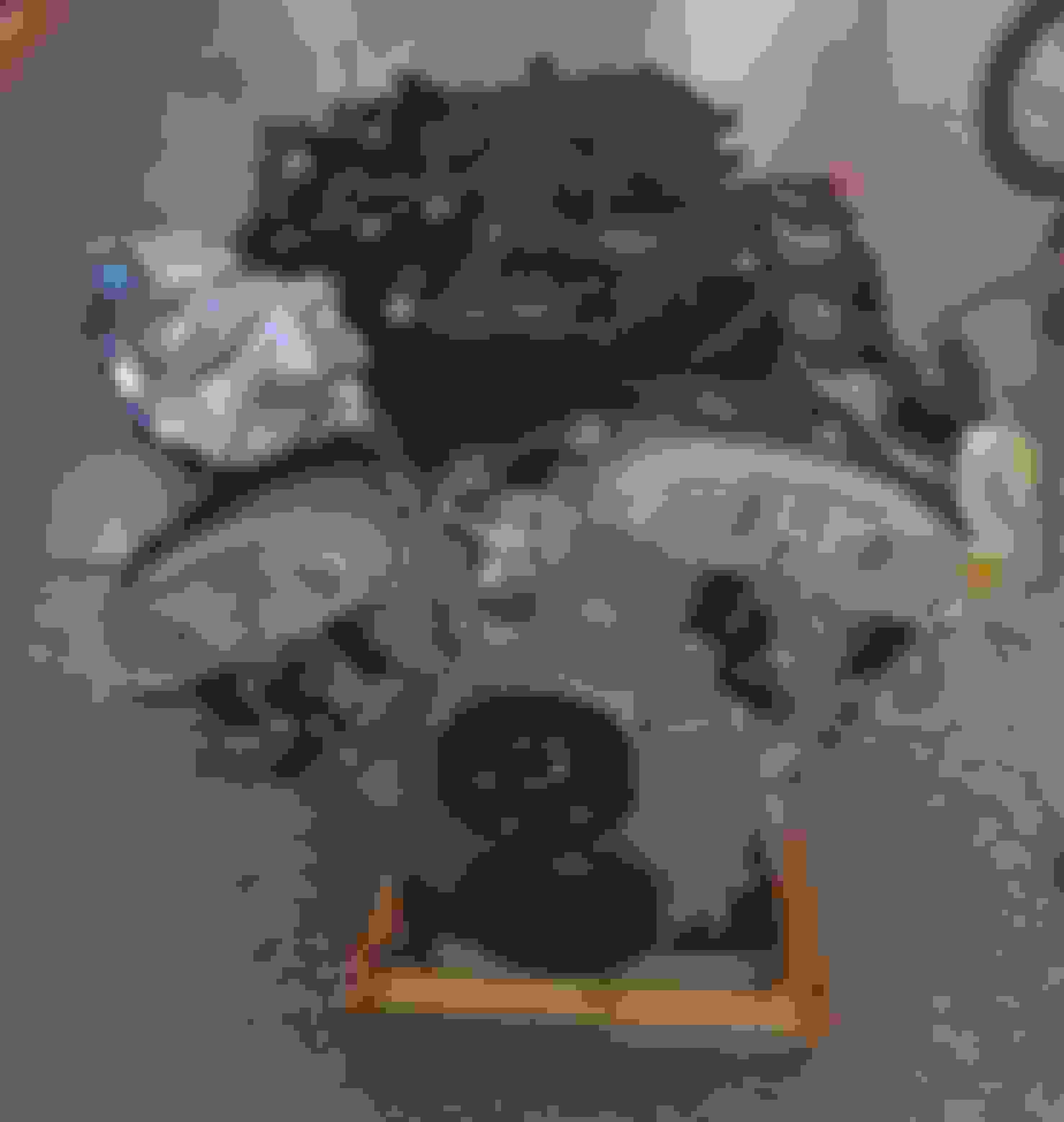
Moving on to the front of the car. I purchased a 2015 LFX with 38k miles on it, removed from a Cadillac XTS, from American Auto Recycling. The pictures below show the condition of the engine when I acquired it. As is often the case with these types of purchases, the recycling shop has stripped off every possible part that they could remove from the engine. That results in a requirement to purchase a lot of parts to dress this engine prior to installation in the car. Here is a listing of the parts I purchased to dress the engine:
Given the number of part I purchased, it would have been nice to have found a fully dressed LFX in a Camaro configuration. However, just the engine cost is about twice the price of the engine I purchased and your would still have to purchase most of the parts listed above. Add to this the desire to find an engine with fairly low mileage at this point in time and there may not be many options.
Front view of Cadillac XTS version of 2105 LFX. Note: This is the transverse mounted front drive configuration of the engine. So, I was required to convert it to the longitudinal mounted configuration to work in this engine swap. Rear view of the engine.
As mentioned previously I purchased Andrews redesigned oil pan for this build. It is a really nice part and like most parts he provided in his kit, it looked good, fit well, and facilitated straightforward assembly. The new part is a very nice casting which eliminates all welds to a modified oil pan and makes for a more professional finished look. However, the real benefit of this new oil pan is the internal baffling designed to keep oil at the pump pickup even during sustained high g maneuvers. He is some pictures Andrew provided which illustrate the new oil pan design Andrew's new oil pan showing oil retention region and baffling. Andrew's new oil pan showing oil retention region and baffling. Andrew's new oil pan showing oil retention region and baffling.
To prepare the engine, the first thing I did was remove the XTS intake manifold. This of course gave me access to the intake valves and like Andrew predicted, even with only 38k miles on the engine, there was already fairly significant oil/carbon debris built up in the valve stems. So, I headed down the path of walnut blasting these with the really cheap walnut blasting gun (Part # 95793) sold by Harbor Freight. With 90 psi and plenty of airflow capacity from my air compressor I couldn't get this to flow well and it was clear that I was going to have walnut shell bits all over everything. Since by this time I had also removed the valve covers, I didn't want to potentially contaminate other engine hardware with these. So, I decided to go another route... I chose to manually clean the valves with Berryman B-12 Chemtool. Prior to spraying this into the intake valve ports, I made sure that the valves were completely closed. Then I literally filled the entire port with chem tool. I let this mixture sit in the port for some time I think 10-15 minutes and them used a slow speed drill with a brass brush on it to agitate and scrub the port wall, valve stem, and back side of the valve head. Having completed this for a few minutes on each valve port, I used a hand vacuum pump to remove the majority of the residual Chemtool. In all but one of the valve ports, one pass was all that was required to get the valves cleaned up pretty well. I think you can do a better job with a properly configured walnut blasting system and a well trained operator. However, I was satisfied that the Chemtool process significantly reduced the intake valve deposits and likely would improve inlet airflow. I've taken a view pictures of the before process after the intake was removed. Unfortunately I did not take after pictures of the intake valves after I was finished cleaning them. There a number of youtube videos out there which describe and illustrate this cleaning process. Top down view of the intake ports after the intake has been removed from the engine. The left side of this picture shows the high pressure fuel pump and supply tubing. Parts of this were replaced to configure the engine like the Camaro. The front of the engine is on the right side of the picture. Trying to get a better picture into the #3 cylinder intake valves Trying to get a better picture into the #5 cylinder intake valves. Note: The valves all had a fairly consistent level of debris and buildup on the valve stems and on the back of the valve heads.
Thanks R3MIX. It was a new experience for me to go through this engine swap process. I'm hoping that those people who take the time to read through this can find something worth-while from the time they spend reading it. It appears now that I was not always very diligent taking photos of the process. I've made many mistakes doing this work and hope to pass those along so others can avoid them. I'll try to tell the story in a way that is entertaining and informative.
Having done many swaps in my years I've never taken enough pictures or documented enough points about them assuming certain aspects to be common knowledge or easily understood. With each project you get better and more adept at planning and seeing potential issues or pitfalls in advance. All the headache, blood sweat and tears only ever seen to show some worth on the "next one" lol.
The mistakes are what you grow from and I for one have learned you never know what tiny bit of info you might include or omit for whatever reason, has someone on the other side of the world digging through threads on some backwater forum using Google translate at 3am to figure something out. Ask me how I know 🤣
Thanks R3MIX. It was a new experience for me to go through this engine swap process. I'm hoping that those people who take the time to read through this can find something worth-while from the time they spend reading it. It appears now that I was not always very diligent taking photos of the process. I've made many mistakes doing this work and hope to pass those along so others can avoid them. I'll try to tell the story in a way that is entertaining and informative.
If you don't mind answering, what is your estimated cost for the swap, not including the vehicle cost.
SparklingFresca,
At the risk of scaring some people away, I'll give you the abbreviated complete rundown of my costs. However, I will also point out that I think Andrew's cost summary for the builder that uses his kit is a pretty good starting point if you don't put in all of the bells and whistles I did and if you buy less of the options Andrew has put together for a fair price. A comparison of his price estimates and my costs:
(Andrews Estimate) ------ My Costs --- Sorry I haven't figure out how to align simple tables here... looked good but spaces removed during upload
Good Condition RX8 roller: ($500- $2000) ------ $1500 minus ($500 engine & $350 for exhaust I sold)
Used drive train components: ($1500 - $3000) ------ $3300 engine, diff, trans, and all engine accessories including conversion from XTS to Camaro configuration
LFX Totality Swap Kit: ($8000) ------ $8000 lots of stuff here (suggest if your really interested going to Andrew's web site https://www.keislerautomation.com/ and look at component brochure
Custom Exhaust ($200 - $1200) ------ $1410 Andrews - downpipes, high flow cats, y-pipe, midpipe (875) and axle back muffler and dressed tail pipes (535)
V1 Track Package ($1000) ------ $1000 Andrew has transitioned this to V2 Track Package (now $1250)
Basic build ($11200-$15200) ------ $15210 Assuming you use Andrews packages like I did.
Additional Options I added
$300 Andrews AC line package
$600 Wilwood front superlight 4 piston calipers through Andrew
$1450 Bilstein B16 PSS9 Coilovers through Andrew
$2873 Enkei RPF1 Wheels 18x10, Yokohama Advan A052 265x35R18 Tires - from discount tire
$1553 Phase 2 Motortrend Inc front upper and rear spherical bearing control arms, ARP wheel studs, and Gorilla Forged Steel lug nuts
Intermediate cost: $21986
All the other small stuff adds up $1822 Clips, Oils, bolts, nuts, Paints, Powder Coating, Thread locker, gasket maker, fasteners, catch can, TPMS sensors, shift **** and boot, etc
Current real price for my car $23807 (includes every cost for parts, hardware, consumables, and a few minor services)
Some might say... wow the car will never be worth that... my reply is that I had the pleasure of doing all the work myself, I learned a hell of a lot completing the swap, and I have a really fun car to drive and race to boot. So, to me, the process was definitely worth the time, money, and effort to complete the research, chase down the parts, work through the trials and tribulations to end up with what I currently have.
Other people are bound to have different options, could I have done things cheaper??? without a doubt... however that wasn't my path.
I learned a very long time ago that any dollar spent on a car besides insurance and gas is a waste of money you'll never get back. With that said I've never cared about what it's worth to someone else now or later. Build it for you to your standards and enjoy it. You can always make more money but you can't always create more time or experiences with something you've built.
I've got roughly the same amount in my 2jz setup and it's completely stock, twins and all. I definitely could have done things differently or cheaper in hindsight but who cares? I enjoy it as much as I can and plan to spend much more very soon lol.
On another note, how's your ride with all those solid bushings and arms? I've got front uppers and some of the rear arms with bc coils and it rides decent enough but idk after going full solid.
Also what's your opinion on Andrews wildwood setup?
So, I never got any good pictures of the intake valves after manually cleaning them with the B16 Clemtool. So, here is the best picture I have. I think this is cylinder #5 after cleaning. Sorry for the terrible picture quality.
To reduce the rate that I foul intake valves when driving the swapped car, I purchased an Elite Engineering catch can for a gen 5 Camaro (Part Number CC302R-LFX-RH-C1B). We went through a number of iterations with them before we got the order correct. The first one I received did not have the mounting holes machined into the case, and the second did not include the filter container and filter media in the top of the catch can. However, they continued to work with me and made things right. So, all this cost me was some additional time and a few emails and photos. I'll talk a bit more about this when I show how/where this was installed in the engine bay.
Next I had removed the valve covers to get a look at the overhead cams and bearing. Additionally, since I had these removed I wanted to clean them up and dress them up with some wrinkle paint. So, I pulled off the fiber blankets that normally top the valve covers and used white scotchbrite pads to clean up and lightly abrade the surface to prepare for the wrinkle paint. I chose the white pads because these provide the mildest abrasion of the aluminum valve covers. I chased down a listing of scotchbrite abrasion/grit levels from 3M and provide it here for people that might be interested
3M Scotch Brite Nylon Pads:
7445 - White pad, called Light Duty Cleansing - (1000) 1200-1500 grit
7448 - Light Grey, called Ultra Fine Hand - (600-800) 800 grit.
6448 - Green (?), called Light Duty Hand Pad - (600) 600 grit
7447 - Maroon pad, called General Purpose Hand - (320-400) 320 grit
6444 - Brown pad, called Extra Duty Hand - (280-320) 240 grit
7446 - Dark Grey pad, called Blending Pad (180-220) 150 grit
7440 - Tan pad, called Heavy Duty Hand Pad - (120-150) 60(?)
Blue Scotch-Brite is considered to be about 1000 grit.
(The value inside the parentheses is directly from 3M.)
Once completed I taped off the valve covers, laid plastic across the garage floor, stacked up the valve covers on top of some open boxes and proceeded to make four passes across the valve covers length wise, width wise, top to bottom, left to right, bottom to top, and right to left. By the time I was done I realized that there was more over-spray than I expected (should have been wearing better PP gear, should have moved more stuff away from the paint area, and should have covered more of the garage floor). After finishing this wrinkle paint process for the first time... I was not happy at all with the results. I probably violated all of the rules of painting. Likely was not the same distance from the surface all the time, didn't account well for all the different surface faces, tried to spot fill during the process for areas I thought were too light, etc.
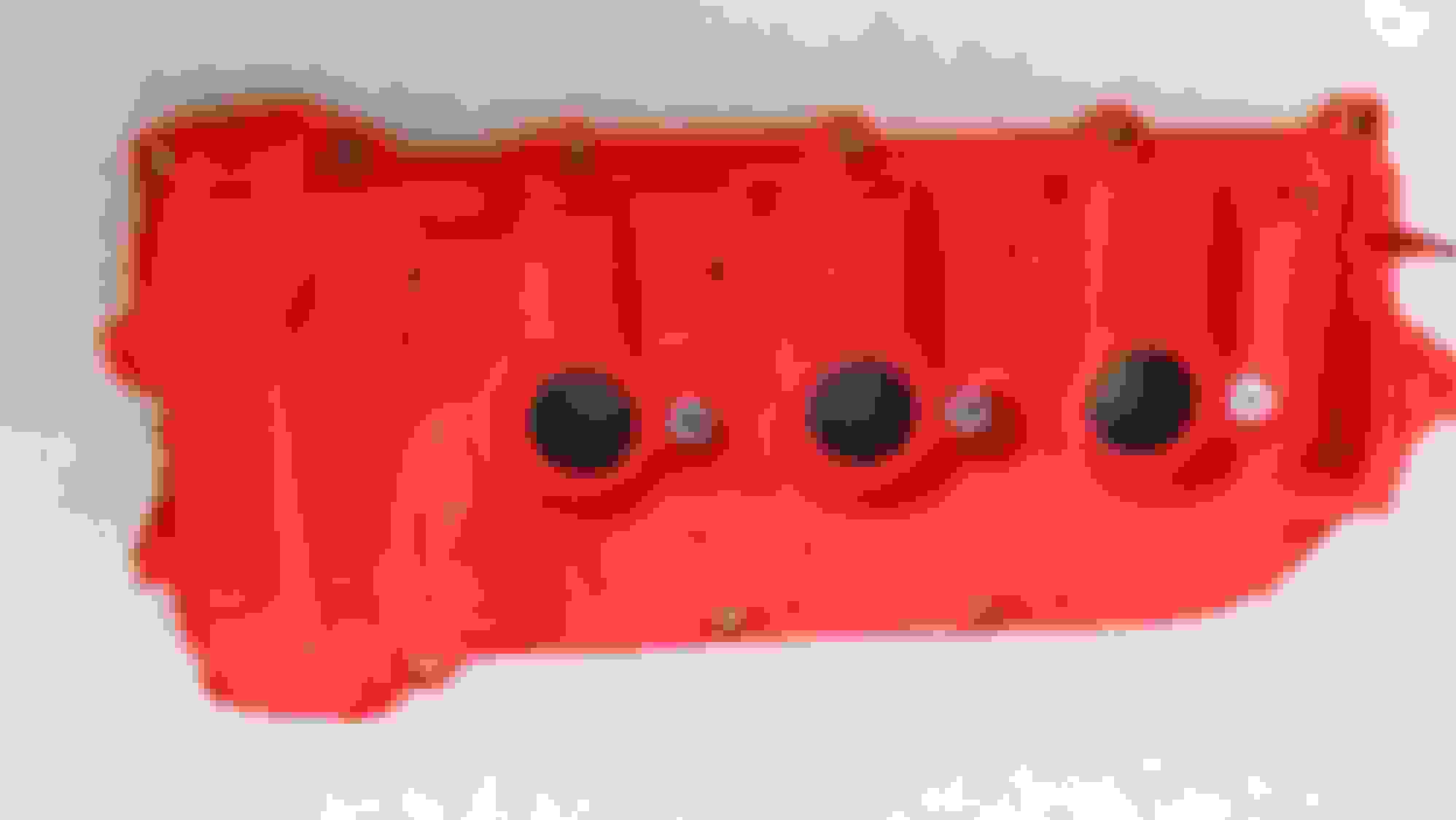
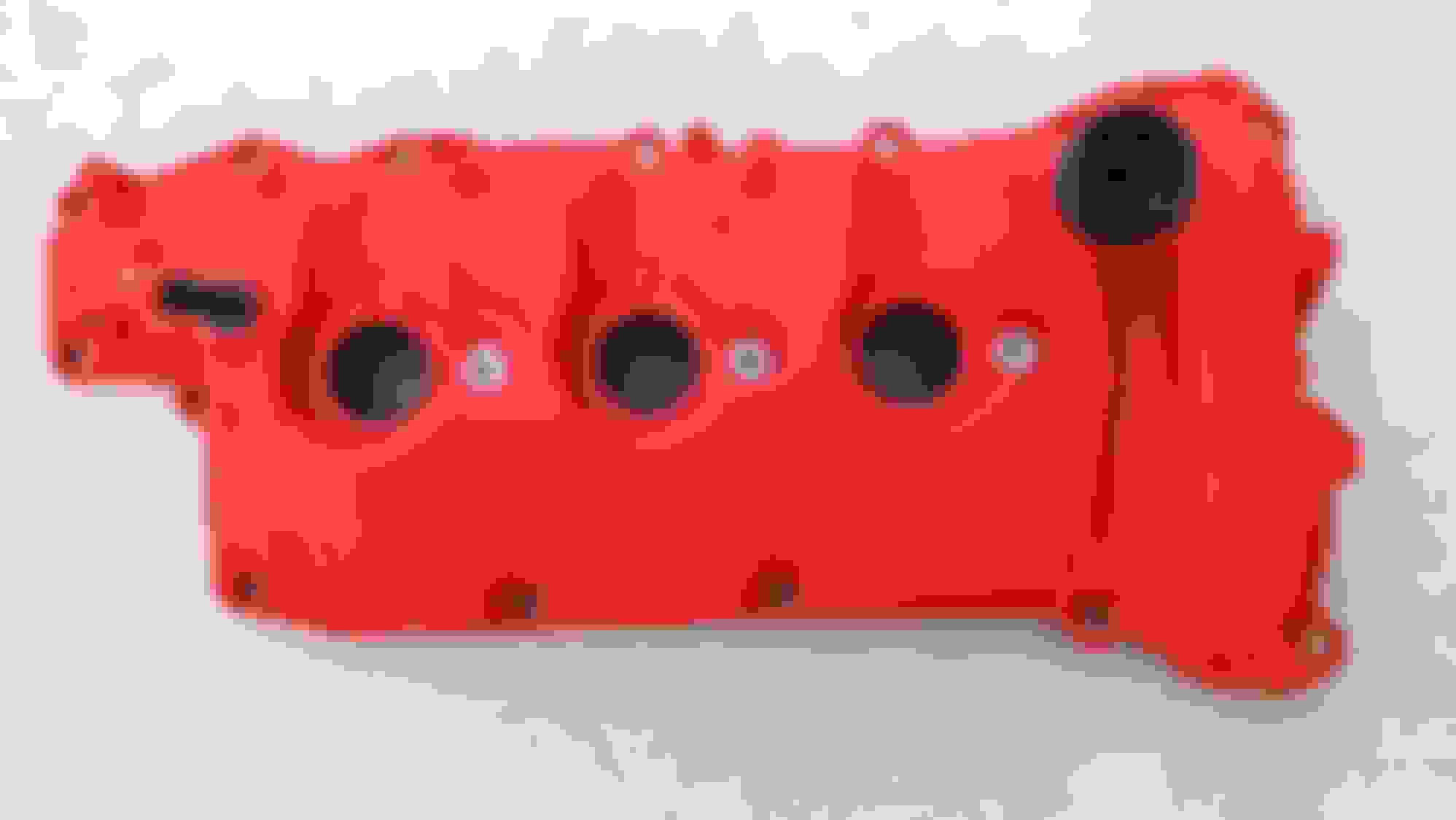
Here are a couple pictures of the results I didn't like... Driver's side valve cover as is plain from the pictures, the wrinkle effect is not even vaguely uniform or consistent. Passenger side valve cover had the same problems as the driver's side. So, in short order I went a bought a few containers of paint stripper and stripped these back to bare metal Both driver's and passenger's valve covers after I stripped off the wrinkle paint. At this point I figured out how to removed the oil fill tube, the PCV valve and removed all of the oil seals. Then I took the valve covers to a local power coating company and had them power coated. I got some color swatches and laid them down on a fender for comparison. While the last swatch was likely a better match of the color, I chose the red winkle finish for the valves cover power coat. Passenger side valve cover as it cam back from power coat. Note: Even though the masked these off somewhat, there was some over-spray cleanup necessary for me to be happy with them. Driver side valve covers after power coating. Needless to say, I am much happier with the power coat finish and even though it cost more, I think it will weather use in the engine bay much better than the wrinkle paint I started with.
One additional comment, care should be taken to pay real attention to the orientation of the seals which seal the spark plug cavities in the valve covers, these can be installed either direction and only one of them is correct. After a brief false start, I went back and looked at pictures of these to make sure I put them in properly. Getting this wrong can easily result in oil soaked spark plugs and a requirement for valve cover removal and new seal swap. Pictures prior to disassembly are a good way to get this right... assuming nobody before you has mucked it up.
I wish I had taken pictures of the cams and vale train when I had the valve covers off. The entire top of the head was very clean with a light covering of clean oil, there was little to no staining of the interior of the valve cover or the cams, valve lobes, or rocker assemblies. This gave me a good feeling about the health of the engine and was at least an indication that the engine had received regular maintenance.
 03-15-2023, 06:12 PM