
Hammer's 2009 Audio Build


Thread Starter
Not an UnRegistered User
Joined: Oct 2009
Posts: 191
Likes: 0
From: Fort Worth, TX
Hammer's 2009 Audio Build
Most of this, I am posting over in DIYMA but thought I would share with you great folks....
Equipment Details:
Kenwood 9980HD H/U
2 - Massive NX4 - Front mid, Front Hi, Rears & Center Amps
Massive N2 - Subwoofer Amp
JBL MS-8 - All 8 channels used
Front - Image Dynamics CTX-6.5cs
Rear - Infinity Reference 9633cf
Center - Polk Audio db351
Subs - Boston Acoustics G210-44
Axxess ASWC Controll
Pioneer ND-BC20PA Backup Camera
0 awg to amp rack
0 awg ground
4 awg to amps
Big 3 Upgrade
CLD / CCF / MLV Entire Car
-----------------------------------------
Wow, I don't believe I am even starting this thread. I finally made a start at this project. A little background... A couple months after getting my car, I knew the audio system had to go. It's not a "bad" Bose system, but it's just not there for me. I also knew that I wanted to quite the car down.
I am not a total SQ guy, nor a bass head. Just something in between. I set out over a year ago and I headed down the carpc route but after about 4 months planning, I scrapped that.
The most important part of this thread: THANK YOU to all the RX-8 Club folks that answered my questions and pointed me in the right direction.
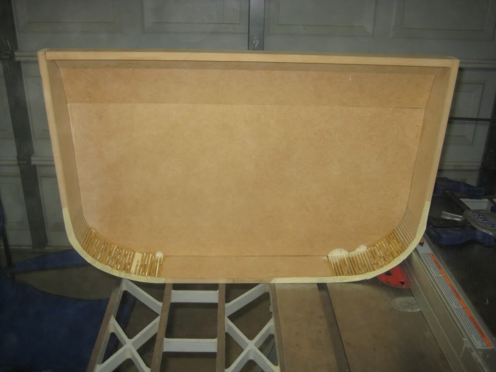
I started off with building the box, after I decided on 2 JBL GTO1014D. I later changed this....
Planning the box:
 This image has been resized. Click this bar to view the full image. The original image is sized %1%2 and weights %3.
To make sure I could get it in and out:
This image has been resized. Click this bar to view the full image. The original image is sized %1%2 and weights %3.
Building the box:
This image has been resized. Click this bar to view the full image. The original image is sized %1%2 and weights %3.
Stuffing and more stuffing:
This image has been resized. Click this bar to view the full image. The original image is sized %1%2 and weights %3.
Covering the box:
This image has been resized. Click this bar to view the full image. The original image is sized %1%2 and weights %3.
Completed enclosure:
This image has been resized. Click this bar to view the full image. The original image is sized %1%2 and weights %3.
I used black as I am still on the hunt for a true match to my carpet color. I have some samples on the way and I can rip this off and cover again if I find a perfect match.
While I was waiting on supplies and just resting, I constructed a solid state relay for remote turnon of amps and DSP processor.This image has been resized. Click this bar to view the full image. The original image is sized %1%2 and weights %3.
Now on to the amp rack that will fit in the trunk floor cutout.
Equipment Details:
Kenwood 9980HD H/U
2 - Massive NX4 - Front mid, Front Hi, Rears & Center Amps
Massive N2 - Subwoofer Amp
JBL MS-8 - All 8 channels used
Front - Image Dynamics CTX-6.5cs
Rear - Infinity Reference 9633cf
Center - Polk Audio db351
Subs - Boston Acoustics G210-44
Axxess ASWC Controll
Pioneer ND-BC20PA Backup Camera
0 awg to amp rack
0 awg ground
4 awg to amps
Big 3 Upgrade
CLD / CCF / MLV Entire Car
-----------------------------------------
Wow, I don't believe I am even starting this thread. I finally made a start at this project. A little background... A couple months after getting my car, I knew the audio system had to go. It's not a "bad" Bose system, but it's just not there for me. I also knew that I wanted to quite the car down.
I am not a total SQ guy, nor a bass head. Just something in between. I set out over a year ago and I headed down the carpc route but after about 4 months planning, I scrapped that.
The most important part of this thread: THANK YOU to all the RX-8 Club folks that answered my questions and pointed me in the right direction.
I started off with building the box, after I decided on 2 JBL GTO1014D. I later changed this....
Planning the box:
This image has been resized. Click this bar to view the full image. The original image is sized %1%2 and weights %3.To make sure I could get it in and out:
This image has been resized. Click this bar to view the full image. The original image is sized %1%2 and weights %3.Building the box:
This image has been resized. Click this bar to view the full image. The original image is sized %1%2 and weights %3.Stuffing and more stuffing:
This image has been resized. Click this bar to view the full image. The original image is sized %1%2 and weights %3.Covering the box:
This image has been resized. Click this bar to view the full image. The original image is sized %1%2 and weights %3.Completed enclosure:
This image has been resized. Click this bar to view the full image. The original image is sized %1%2 and weights %3.I used black as I am still on the hunt for a true match to my carpet color. I have some samples on the way and I can rip this off and cover again if I find a perfect match.
While I was waiting on supplies and just resting, I constructed a solid state relay for remote turnon of amps and DSP processor.
This image has been resized. Click this bar to view the full image. The original image is sized %1%2 and weights %3.Now on to the amp rack that will fit in the trunk floor cutout.
Last edited by bhammer; Feb 18, 2012 at 12:54 AM.
Thread Starter
Not an UnRegistered User
Joined: Oct 2009
Posts: 191
Likes: 0
From: Fort Worth, TX
Because of the limited space, I was limited on my selection of amps. I decided to go 2 Massive NX-4 for front stage and center and an N2 for the subs. I made a small tray out of 1/2" MDF to fit in the "box" in the trunk floor. I had thought about glassing it and probably will before this project is completed. The most annoying part of this was all the kurf cuts to fit make the bends. Glue is curing as I write. Cleanup, sanding, lid building and covering comes later.
This image has been resized. Click this bar to view the full image. The original image is sized %1%2 and weights %3.
Oh wait, who is that I see coming of the street. Wait, is it brown? Yes it is. Come on, no, don't stop there. Dang, I thought the UPS man had something for me...... Oh wait, he's stopping at my house; whoo hoooo!!

This image has been resized. Click this bar to view the full image. The original image is sized %1%2 and weights %3.
The start of the sound deadening job. Damn, the MLV is HEAVY!!!! I am sure some of you guys that try to strip every pound are baulking at this. Still waiting on one more box due to a mix up in shipping.
On Wednesday, I'll be at the hangar and plan to weigh the car and compute the CG now and after. I am expecting about 130lbs for this install. I am also going to take some baseline SIL measurements to see what effect the deadening job has.
More to follow as I start to remove the interior and the fun begins.
This image has been resized. Click this bar to view the full image. The original image is sized %1%2 and weights %3.Oh wait, who is that I see coming of the street. Wait, is it brown? Yes it is. Come on, no, don't stop there. Dang, I thought the UPS man had something for me...... Oh wait, he's stopping at my house; whoo hoooo!!
This image has been resized. Click this bar to view the full image. The original image is sized %1%2 and weights %3.The start of the sound deadening job. Damn, the MLV is HEAVY!!!! I am sure some of you guys that try to strip every pound are baulking at this. Still waiting on one more box due to a mix up in shipping.
On Wednesday, I'll be at the hangar and plan to weigh the car and compute the CG now and after. I am expecting about 130lbs for this install. I am also going to take some baseline SIL measurements to see what effect the deadening job has.
More to follow as I start to remove the interior and the fun begins.
Thread Starter
Not an UnRegistered User
Joined: Oct 2009
Posts: 191
Likes: 0
From: Fort Worth, TX
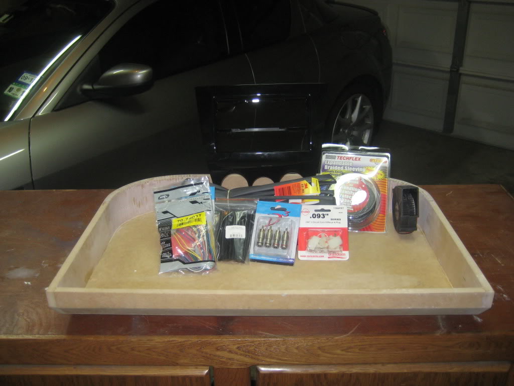
More goodies came in today. I received a lot of the stuff to make my own RCA cables and the Metra face plate. I also finished up building the tray and the lid. I am waiting to wrap them in carpet until the amps arrive. This way I can lay them out and place the cooling fan and make a final cut. I plan to use the rotorary image for the cooling fan intake.
Thread Starter
Not an UnRegistered User
Joined: Oct 2009
Posts: 191
Likes: 0
From: Fort Worth, TX
Before I begin the sound deadening project on Friday, I took some simple dB sound levels using my Atrix Android phone and Sound Meter Pro by Smart Tools. Several weeks ago, I was at Measurement Assurance Technology dropping off tools that needed calibration. We took a quick look at the phone and made a couple adjustments. It is calibrated from 40 to 95 dB to about +/- 5%. I was surprised at just how accurate the phone mic is. The phone is limited to 100 db and has a difficult time measuring under 40dB.
I plan to do the same type of drive after the project is completed.
http://youtu.be/4abj7BpPzx4
I plan to do the same type of drive after the project is completed.
http://youtu.be/4abj7BpPzx4
Thread Starter
Not an UnRegistered User
Joined: Oct 2009
Posts: 191
Likes: 0
From: Fort Worth, TX
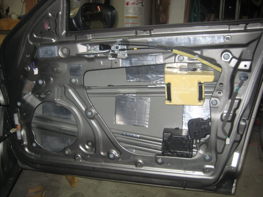
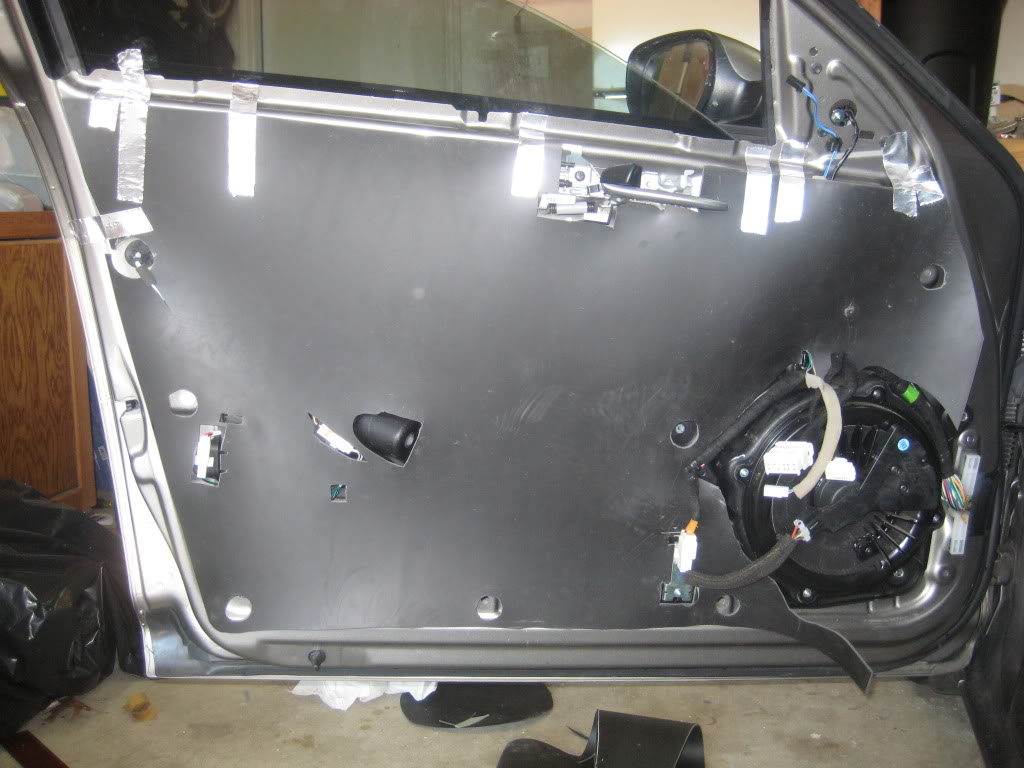
I spent some time the last several days working on the CLD/CCF/MLV application in the front doors and the trunk. I still need to do a little trim work for the front doors as the panels have a gap on the aft edge about in the middle. If I trim the MLV back by about 1/8" and remove the CCF about 1/2", they will fit snug again.
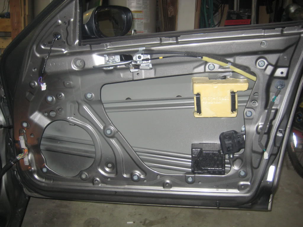
On the inner skin that only had one layer, I applied the CLD on the inside between glass. Where there were two layers, I added it to the cabin side. I was actually surprised at just has the inner skins had very little resonance to them. The outer skin, well, that is a another story. When I finished up the passenger door, I listened to some tunes. You can hear a definate difference between the two. I huge improvement.
Once I mount my replacement speakers, I'll trim it up with MLV.
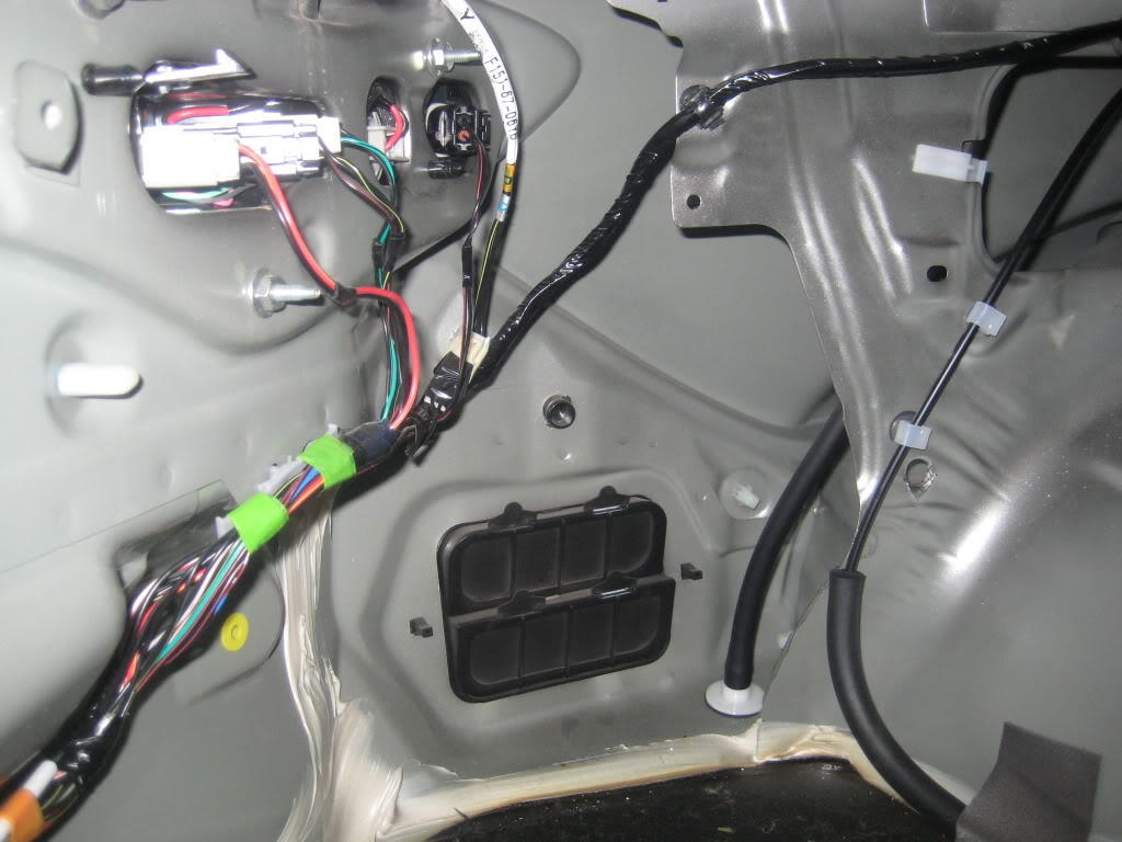
Not yet finished with the trunk. The way I am doing this is that the strip that ties pieces together are not glued to both sides. This way, if I have to remove it at latter date I can.
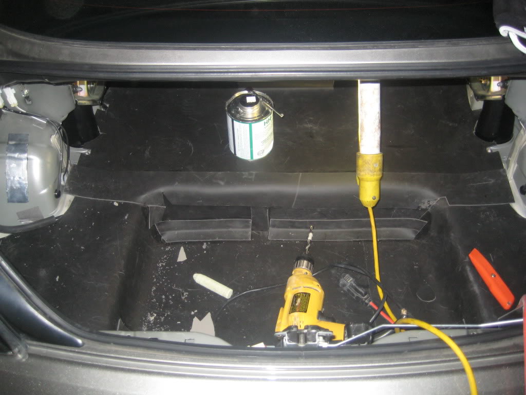
I find it intersting that Mazda though about about air pressure (my assumption) in the trunk. They added one way valves to allow air out of the trunk.
On the inner skin that only had one layer, I applied the CLD on the inside between glass. Where there were two layers, I added it to the cabin side. I was actually surprised at just has the inner skins had very little resonance to them. The outer skin, well, that is a another story. When I finished up the passenger door, I listened to some tunes. You can hear a definate difference between the two. I huge improvement.
Once I mount my replacement speakers, I'll trim it up with MLV.
Not yet finished with the trunk. The way I am doing this is that the strip that ties pieces together are not glued to both sides. This way, if I have to remove it at latter date I can.
I find it intersting that Mazda though about about air pressure (my assumption) in the trunk. They added one way valves to allow air out of the trunk.

Registered
Joined: Dec 2010
Posts: 229
Likes: 0
From: Dearborn Heights, MI
Subscribed to your thread. Looking forward to the finished product. I am planning on adding some sound insulation to my 8 but I hate ripping apart the interior. On my other car, some things didn't go back as smoothly as I hoped.
BTW every manufacturer uses those pressure relieving valves.
BTW every manufacturer uses those pressure relieving valves.
Thread Starter
Not an UnRegistered User
Joined: Oct 2009
Posts: 191
Likes: 0
From: Fort Worth, TX
Getting the interior parts to fit back in after adding the deadening is tough. I had issues in the trunk getting it to all go back as normal. I still have a little wrinkle in the carpet becasue I didn't remove the insulation that is there. I am giving it a couple days to see if it will lay flat.
More work this weekend.
More work this weekend.
Thread Starter
Not an UnRegistered User
Joined: Oct 2009
Posts: 191
Likes: 0
From: Fort Worth, TX
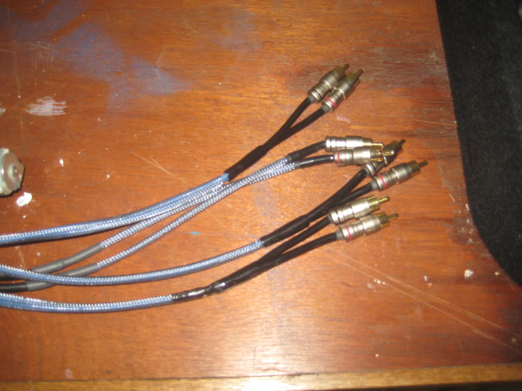
I've had some time over the last couple of days to get some more completed on the build. I made my RCA cables based on the DIYMobileAudio RCA DIY thread. I think I did it right by soldering the shield to only one end ground.
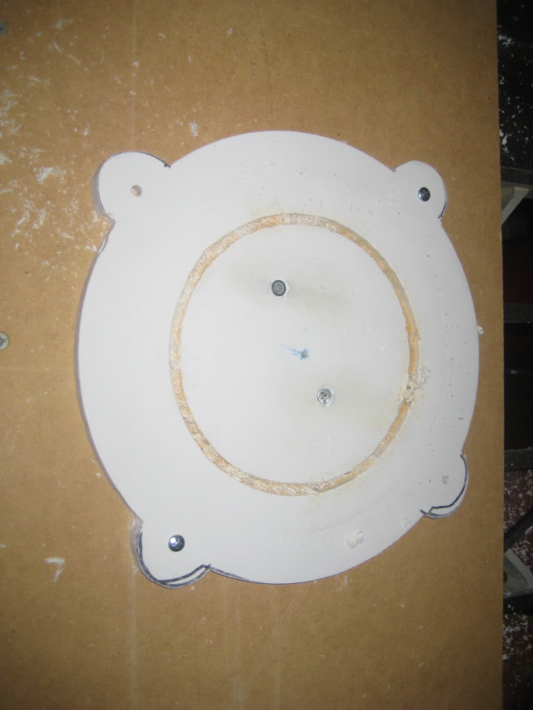
I'm going with Image Dynamics for the front stage.
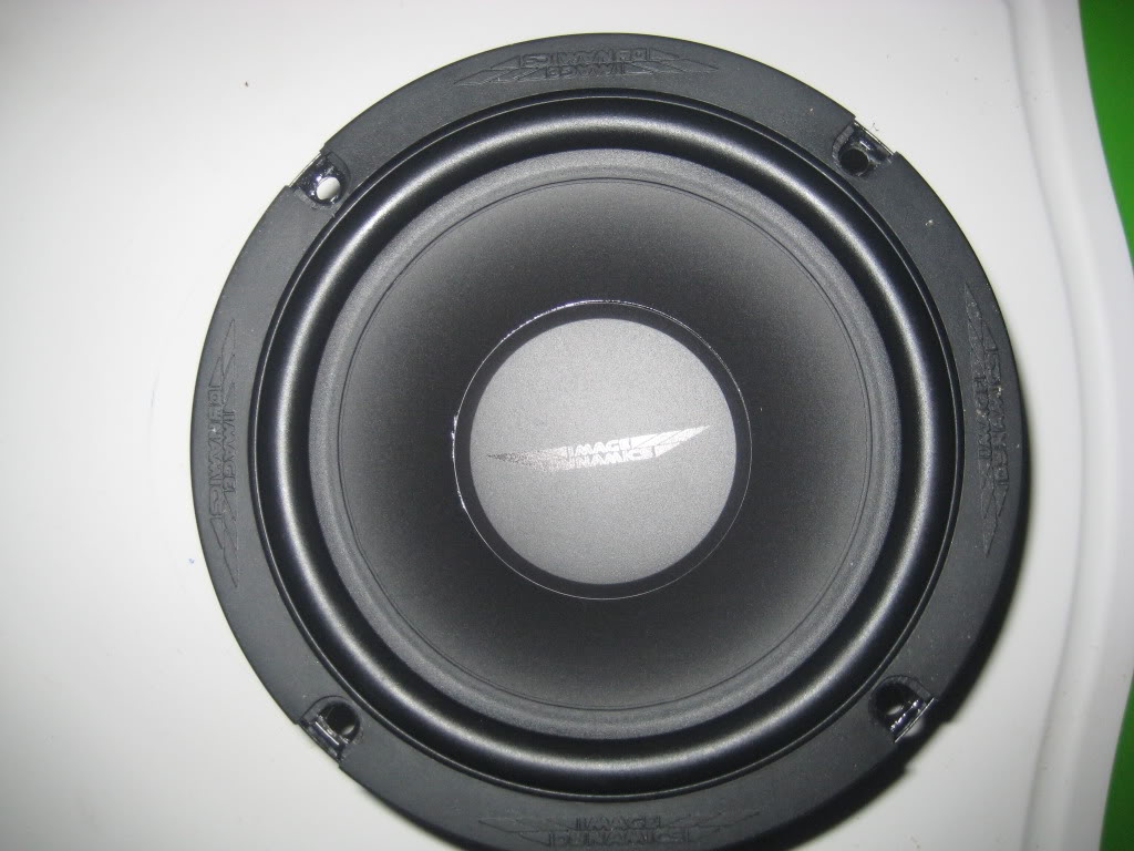
The car has Bose 8.5" woofers there now so I had created an adapter. Don't tell my wife, but I stole her cutting boards to use for the adapters. :D I used a dremel with the circle adapter to make the cuts.
I'm going with Image Dynamics for the front stage.
The car has Bose 8.5" woofers there now so I had created an adapter. Don't tell my wife, but I stole her cutting boards to use for the adapters. :D I used a dremel with the circle adapter to make the cuts.

I dont know much about the S2 RX8's, but is the trunk so different from the S1's that this box wouldn't work? It's not much more money than the bare materials themselves and certainly worth the hours of saved labor IMO.
Thread Starter
Not an UnRegistered User
Joined: Oct 2009
Posts: 191
Likes: 0
From: Fort Worth, TX
I dont know much about the S2 RX8's, but is the trunk so different from the S1's that this box wouldn't work?
It's not much more money than the bare materials themselves and certainly worth the hours of saved labor IMO
Now, ask me about yard work, yup, I pay someone $35 every week to come take care of it for me.

Thread Starter
Not an UnRegistered User
Joined: Oct 2009
Posts: 191
Likes: 0
From: Fort Worth, TX
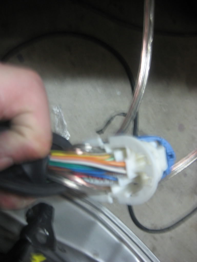
A little more work last night and this morning. No more work says the wife until I go to Wal-Mart and get her new cutting boards.  I built up the wire harness. One end goes to the car side plug, to the radio and Axxess. The white plug will go to the factory radio when I need to adjust the clock. It'll stay tucked away when the factory is not plugged in.
This image has been resized. Click this bar to view the full image. The original image is sized %1%2 and weights %3.

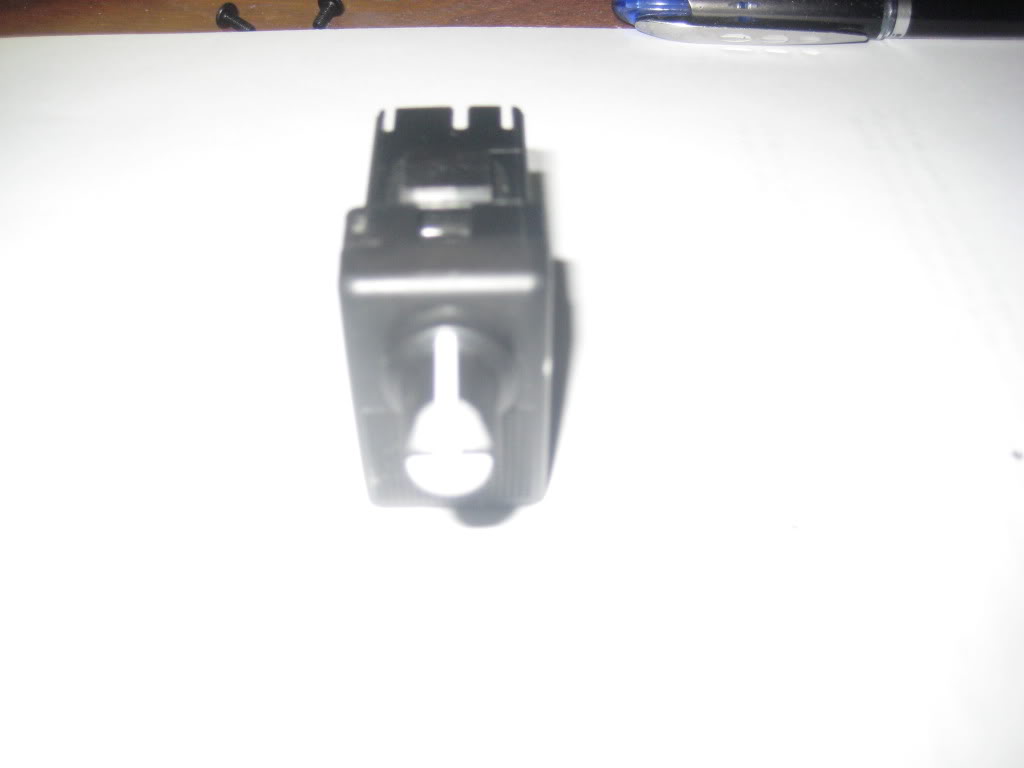
I also modified one of the blank out plugs for the base boost switch. I don't know if I'll ever use it, but it'll be there.
This image has been resized. Click this bar to view the full image. The original image is sized %1%2 and weights %3.
I built up the wire harness. One end goes to the car side plug, to the radio and Axxess. The white plug will go to the factory radio when I need to adjust the clock. It'll stay tucked away when the factory is not plugged in. This image has been resized. Click this bar to view the full image. The original image is sized %1%2 and weights %3.I also modified one of the blank out plugs for the base boost switch. I don't know if I'll ever use it, but it'll be there.
This image has been resized. Click this bar to view the full image. The original image is sized %1%2 and weights %3.
Thread Starter
Not an UnRegistered User
Joined: Oct 2009
Posts: 191
Likes: 0
From: Fort Worth, TX
Ok, I have been slow on getting you guys updates... So here it is.
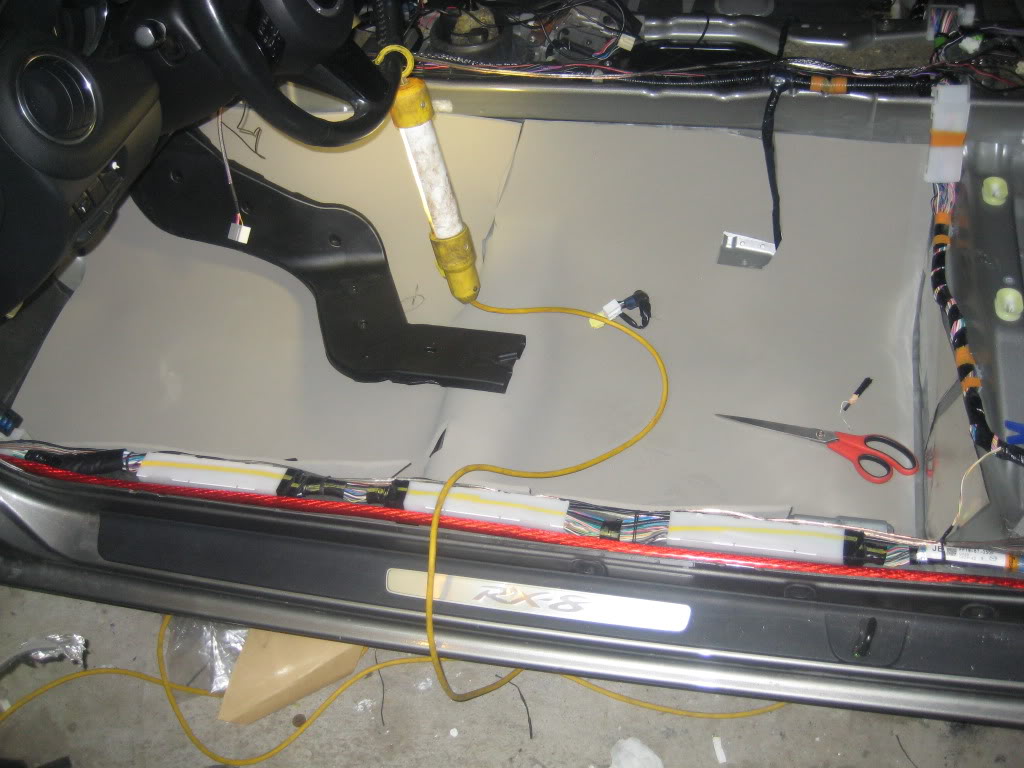
I took the entire interior out, minus the dash and laid down the CLD tiles, CCF and MLV. As is the case with most cars, the floor had much of the area covered with vibration dampening and I left it in place. The most difficult part of the sound part was the transmission tunnel. There is just a lot of wiring and connection points to work around. I can't find the couple images I have of the MLV portion.
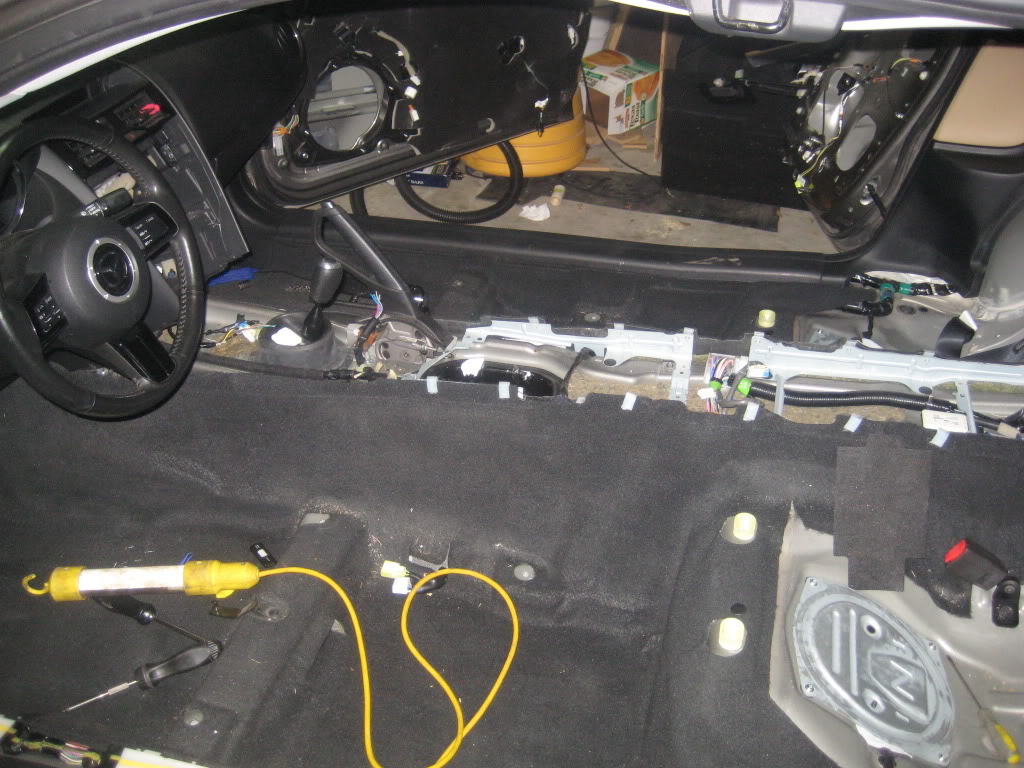
Some tips with this stuff. A heat gun does wonders helping to mold it. I found that the utility knife blades with the hook are the best for cutting MLV and commercial long shears for the CCF. Wear gloves when applying the CLD tiles as they can cut you quick. In my testing with the CLD, I found that more smaller pieces works better than one large one. I used the plastic snaps to size of the cut out holes to minimize opening sizes.
The first thing I decided to do was to modify the shark fin antenna to use the new Sirius antenna.
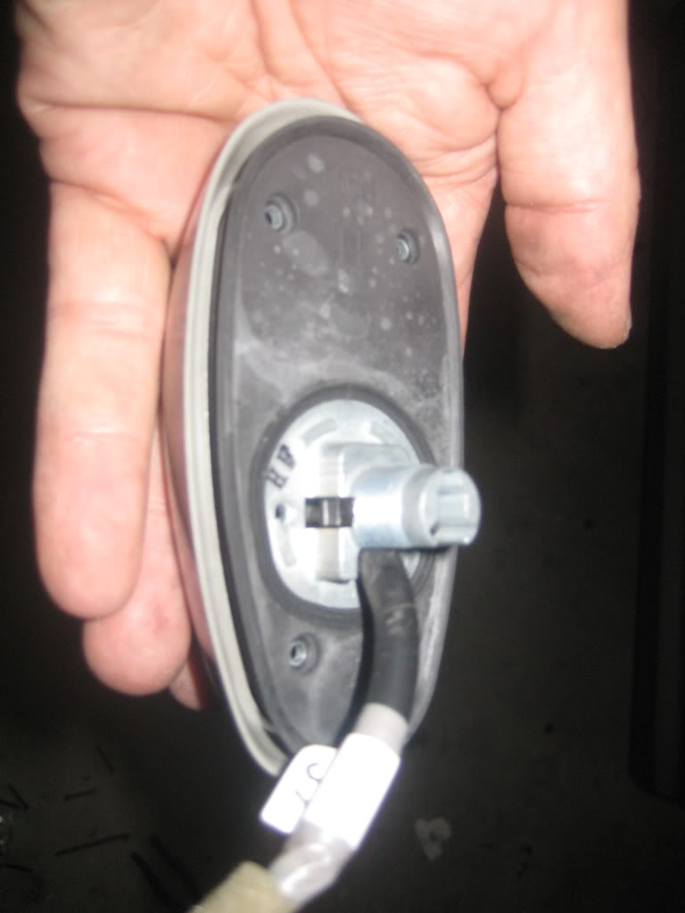
Here is the factory antenna used
with the antenna removed
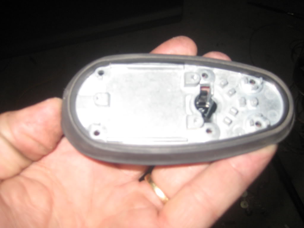
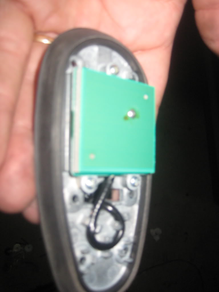
Base plate for the factory antenna that I modified to fit the new, slightly larger antenna
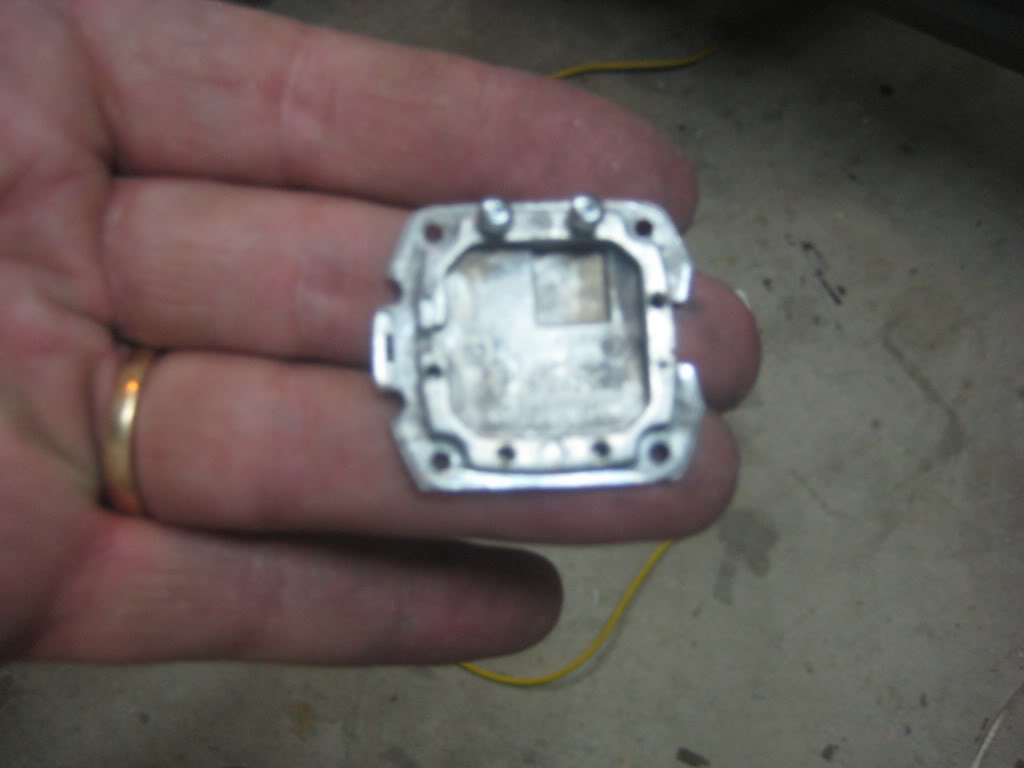
Here it is installed with a little JB weld to hold it in place. I didn't need to add the JB, just thought I would for extra measure.
I took the entire interior out, minus the dash and laid down the CLD tiles, CCF and MLV. As is the case with most cars, the floor had much of the area covered with vibration dampening and I left it in place. The most difficult part of the sound part was the transmission tunnel. There is just a lot of wiring and connection points to work around. I can't find the couple images I have of the MLV portion.
Some tips with this stuff. A heat gun does wonders helping to mold it. I found that the utility knife blades with the hook are the best for cutting MLV and commercial long shears for the CCF. Wear gloves when applying the CLD tiles as they can cut you quick. In my testing with the CLD, I found that more smaller pieces works better than one large one. I used the plastic snaps to size of the cut out holes to minimize opening sizes.
The first thing I decided to do was to modify the shark fin antenna to use the new Sirius antenna.
Here is the factory antenna used
with the antenna removed
Base plate for the factory antenna that I modified to fit the new, slightly larger antenna
Here it is installed with a little JB weld to hold it in place. I didn't need to add the JB, just thought I would for extra measure.
Thread Starter
Not an UnRegistered User
Joined: Oct 2009
Posts: 191
Likes: 0
From: Fort Worth, TX
For the front doors, I used the existing harness. Since this car had factory Bose, I didn't have any open space in the plug unless I wanted to de-pin the Bose wires. I wanted to leave them there in case I want to switch back to sell the car.
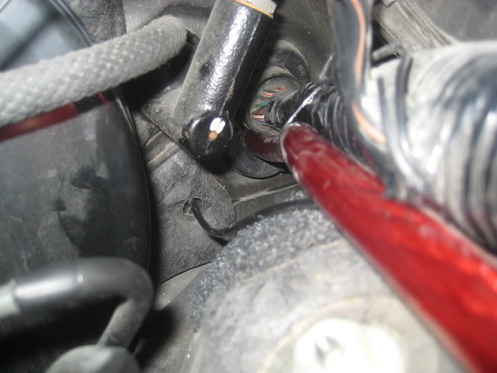
By doing it this way, I had to trim into the car a little for the speaker wire. After I notched out an opening, I etched the surface and them primmed it. The notches hide nicely behind the boot.
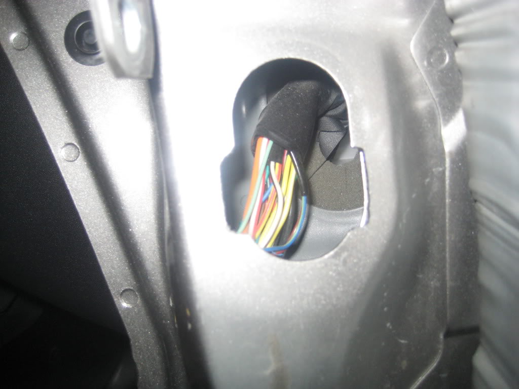
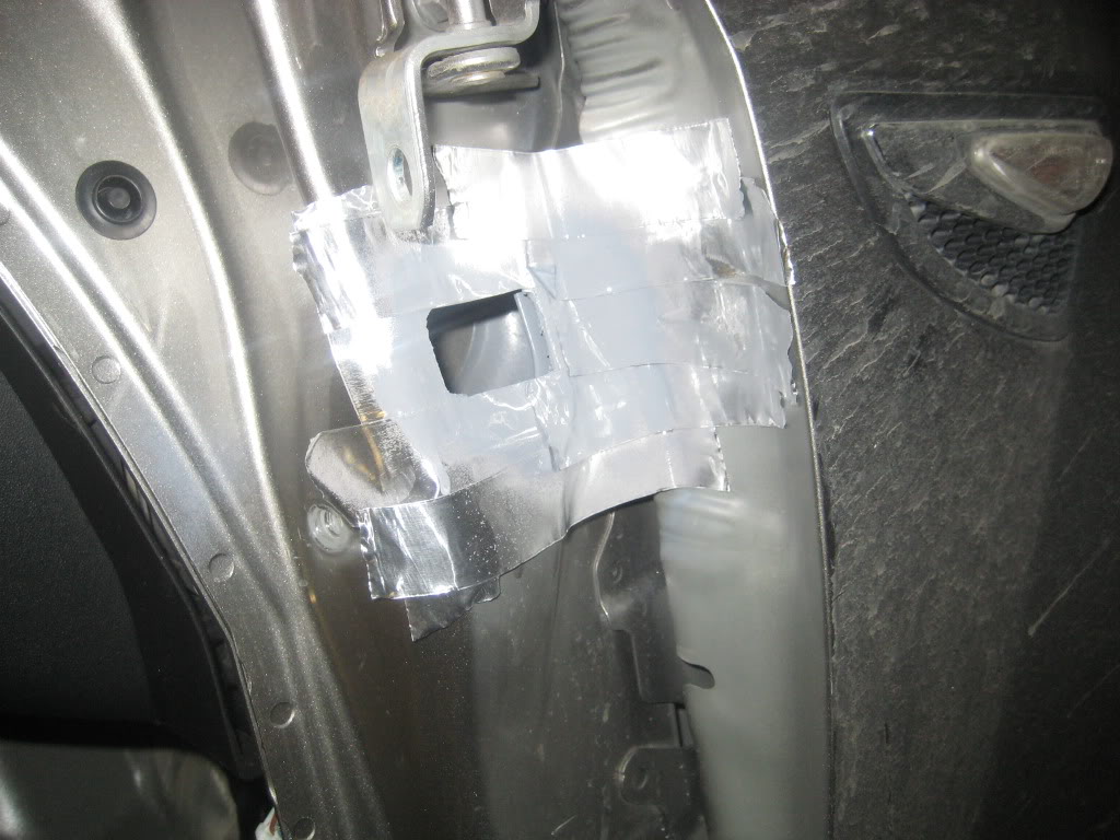
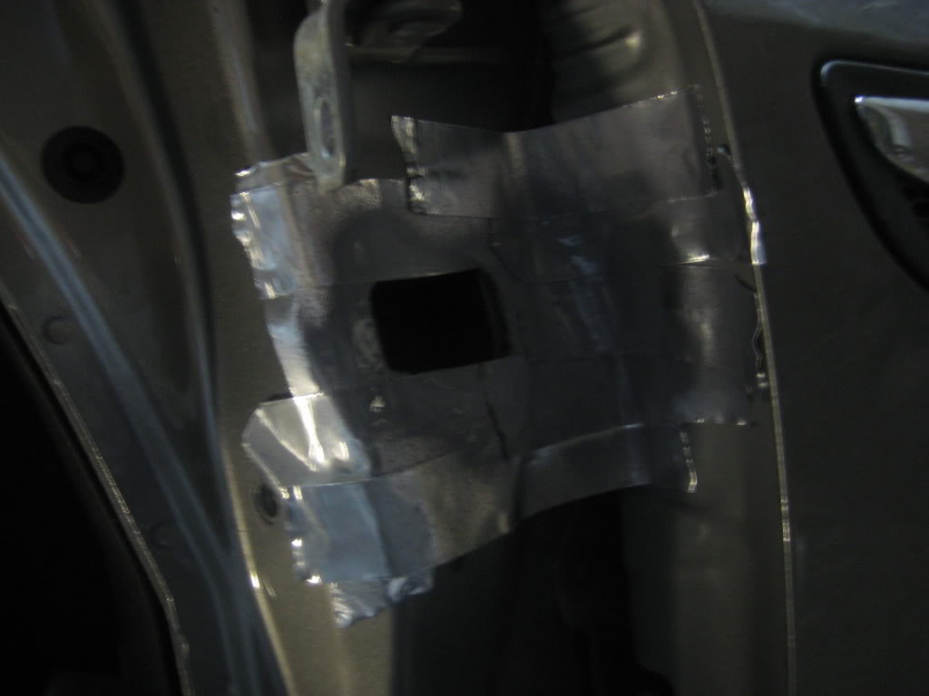
After all was dry, I used liquid rubber on the metal and wrapped the wire in tape so I didn't end up with chaffing.
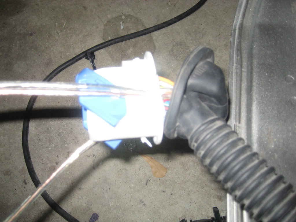
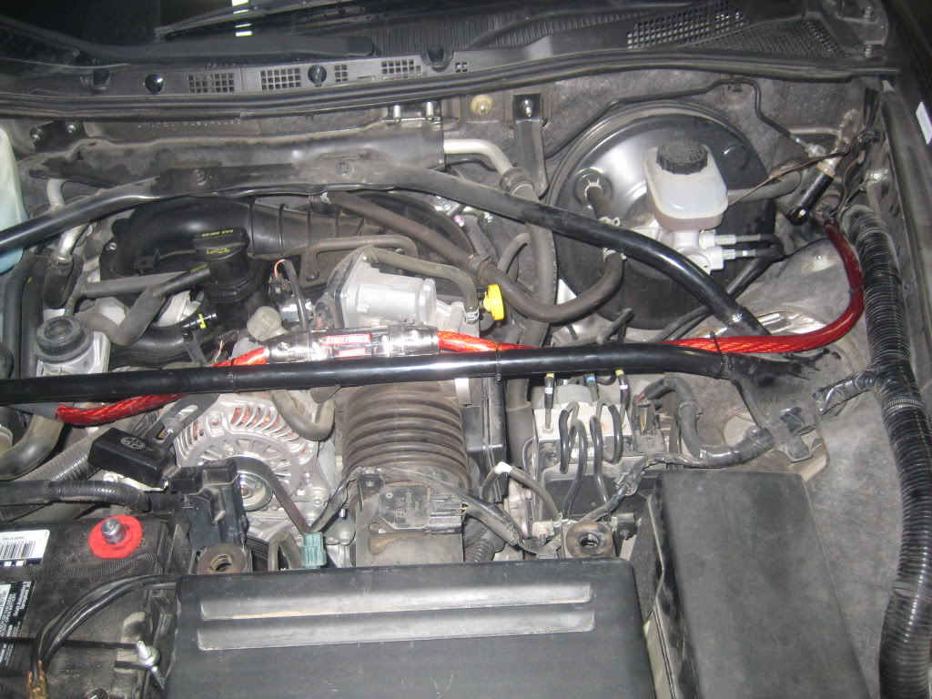
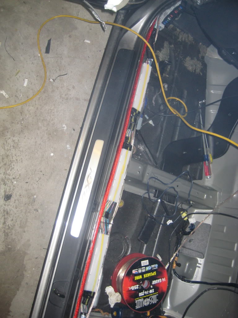
I used the existing firewall wire run to run my 0 awg wire from the battery into the cabin. I ran the wire down the left side.
I had to remove the white boxes in order to get the trim to snap back in. So I used spiral wrap around all the factory wiring in its place.
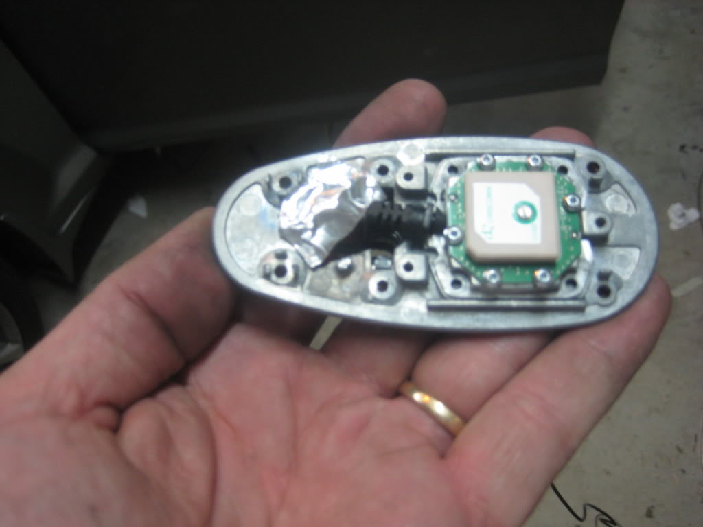
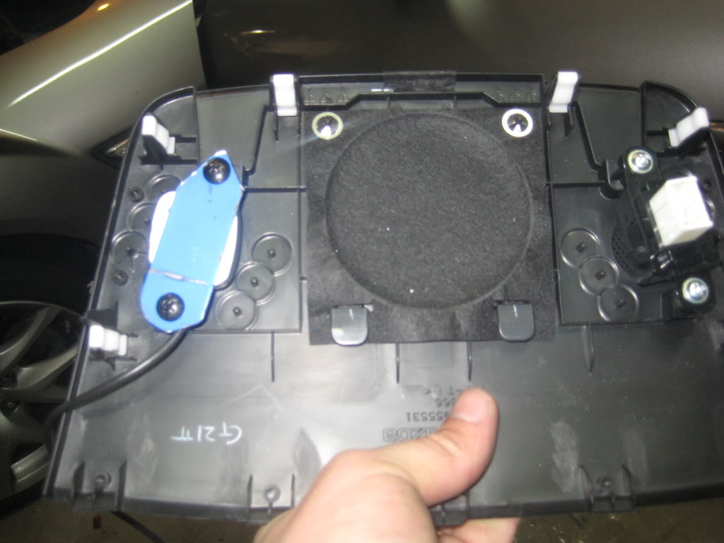
I used the center speaker location to mount the nav antenna and the 3.5" speaker. The blue part is a scrap ferrous metal for the GPS antenna magnet.
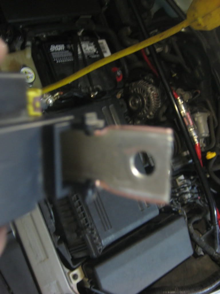
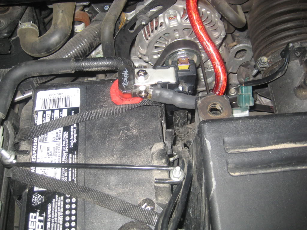
Time to modify the battery connection. Here is the factory end used to connect the alternator input and the 60 accessory fuse.
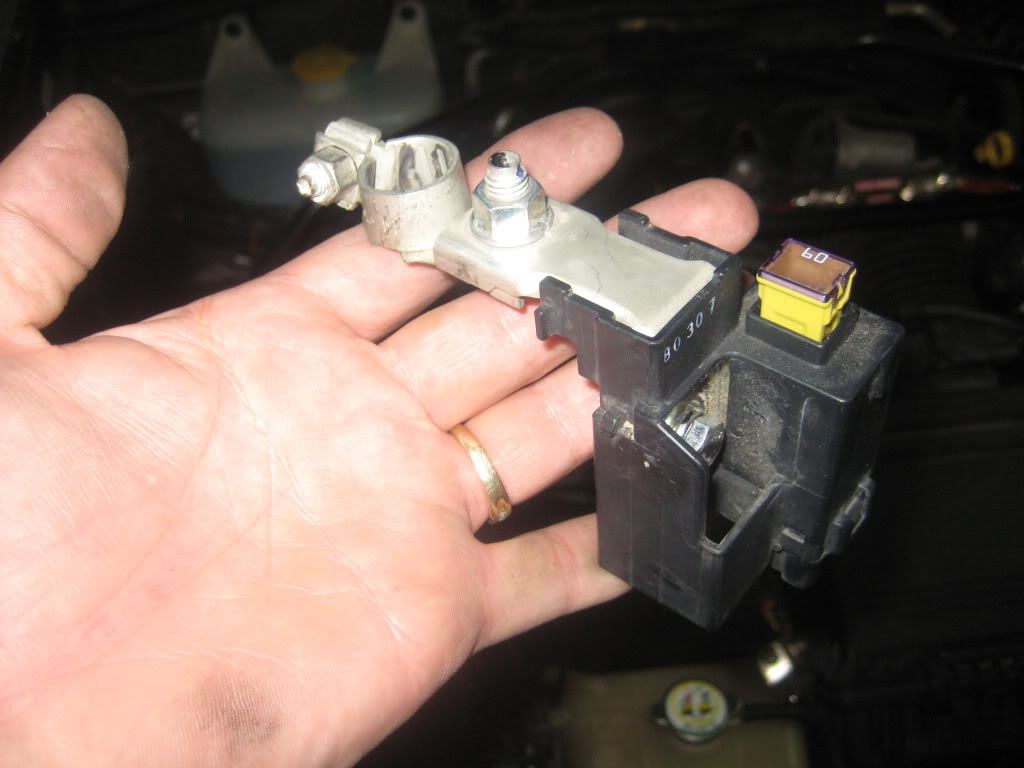
Cut off the side tabs so it'll fit the new battery connector.
Hooked up
By doing it this way, I had to trim into the car a little for the speaker wire. After I notched out an opening, I etched the surface and them primmed it. The notches hide nicely behind the boot.
After all was dry, I used liquid rubber on the metal and wrapped the wire in tape so I didn't end up with chaffing.
I used the existing firewall wire run to run my 0 awg wire from the battery into the cabin. I ran the wire down the left side.
I had to remove the white boxes in order to get the trim to snap back in. So I used spiral wrap around all the factory wiring in its place.
I used the center speaker location to mount the nav antenna and the 3.5" speaker. The blue part is a scrap ferrous metal for the GPS antenna magnet.
Time to modify the battery connection. Here is the factory end used to connect the alternator input and the 60 accessory fuse.
Cut off the side tabs so it'll fit the new battery connector.
Hooked up
Last edited by bhammer; Feb 17, 2012 at 11:04 PM.
Thread Starter
Not an UnRegistered User
Joined: Oct 2009
Posts: 191
Likes: 0
From: Fort Worth, TX
Oh, just found a picture with some of CCF down. It's 1/2" CCF on the floor.
Here is the new unit installed with a custom boot screen.
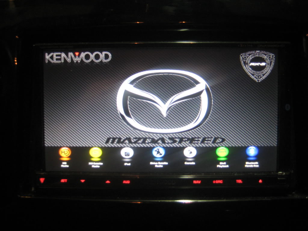
I've uploaded the nav files with Garmin's newest files and activated the NavTeq and TTN traffic.
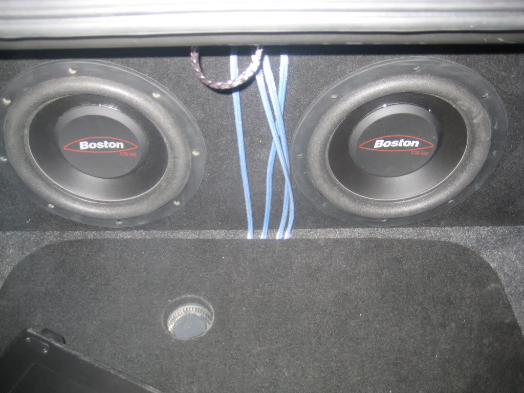
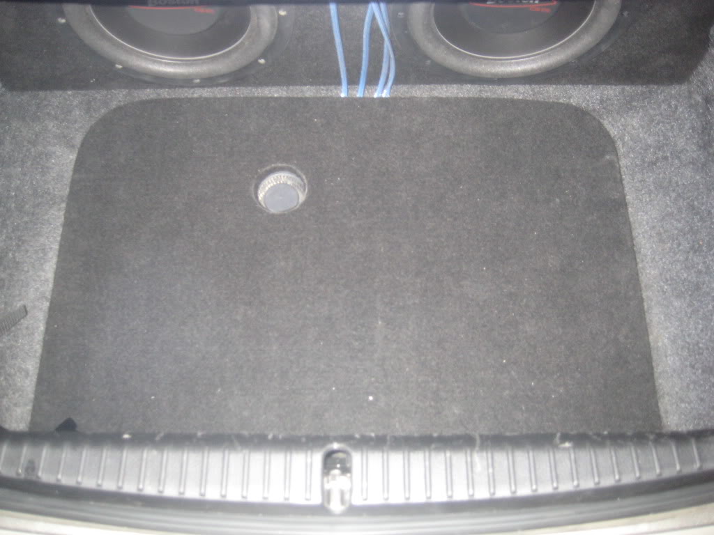
Here is the speaker box and amp rack. The MS-8 is mounted the rear deck and didn't take any pictures of it.
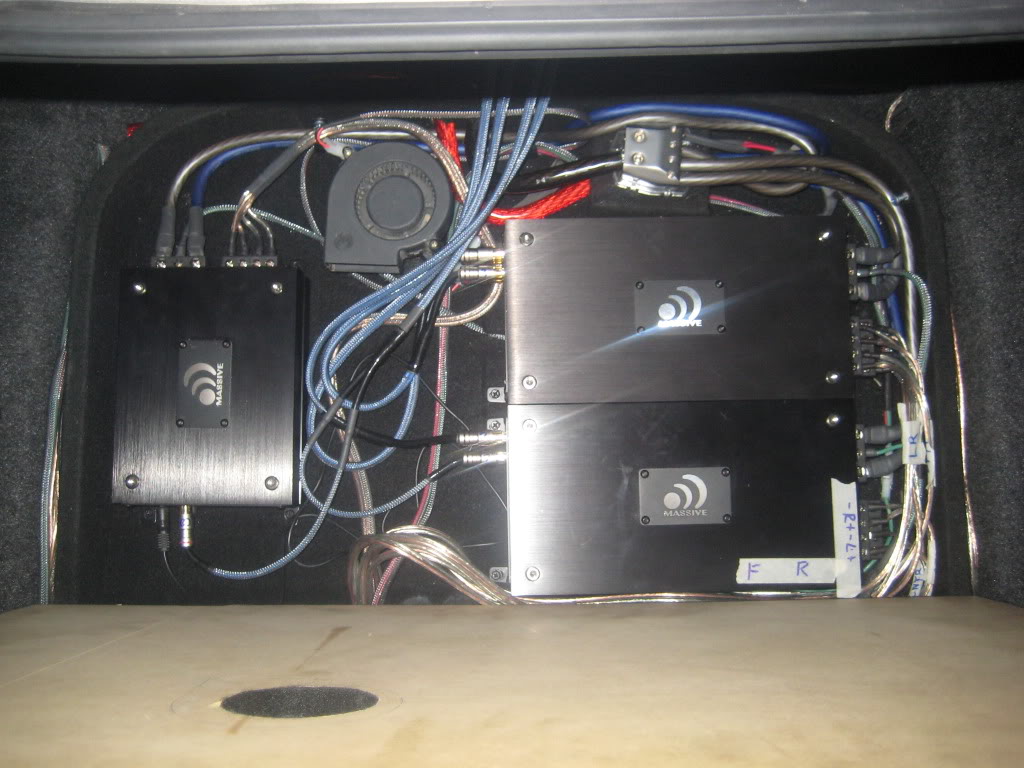
Amp cover
Ignore the RCA cables. I have to make some new ones as I changed the MS-8 location during intall and these were too short. I plan to do that this weekend.
Here is the new unit installed with a custom boot screen.
I've uploaded the nav files with Garmin's newest files and activated the NavTeq and TTN traffic.
Here is the speaker box and amp rack. The MS-8 is mounted the rear deck and didn't take any pictures of it.
Amp cover
Ignore the RCA cables. I have to make some new ones as I changed the MS-8 location during intall and these were too short. I plan to do that this weekend.
Thread Starter
Not an UnRegistered User
Joined: Oct 2009
Posts: 191
Likes: 0
From: Fort Worth, TX
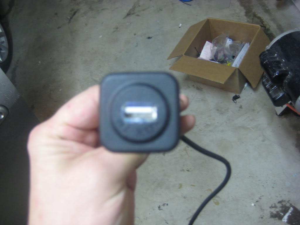
I modified the aux input in the center arm rest to accept the new USB connections. I thought it would also charge my phone but is too slow. I think the amp output is low compared to using a standard accessory plug output.
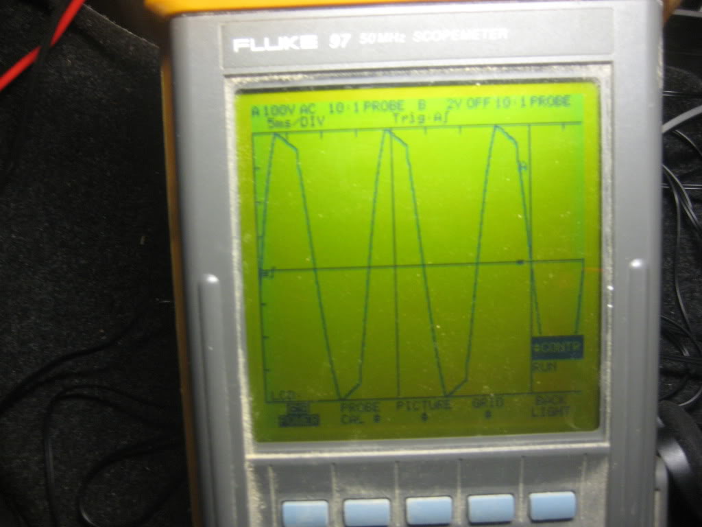
I have to say that in the past, I used a DMM to set gains. I used two online calculators to verify proper settings and tried that first. Then, I used my oscope to set/check the gains. I was surprised that the DMM route was close but was still clipping. This is how far I was off.
So far, I am very happy with the system. I am still playing around with the MS-8 and have tried a dozen or so combinations. I have to admit, I have thought more than once to bypass it and use the sound features of the head unit instead. I think I need to get a RTA and set the eq with that. I still seem to have a little bit of hollow sound. My settings for the setup are:
Subsonic @35/12
Sub front @ 95/24
Front lo hi @ 4500/24
Center hi pass @ 150/24
Side hi pass @ 60/24
The only issue I seem to have is the volume of the head unit seems a bit low. I set the MS8 at -35 when doing the settings and then -7 for regular running.
Also, based on my crossover points, what test tones should I use to set the gains properly. I think I used 62 for subs, 200 for front lo and center, 6500 for front hi and 100 for the sides/rear.
Any thoughts on this would be great.
Just to make sure we're on the same page, "Sub front @ 95/24" is the LP filter for the sub set at 95Hz with a 24db/octave rolloff? What does "Front lo hi" mean? LP for the front 6 1/2"? And "Side hi pass" refers to the front 6 1/2" too?
Oh and running speaker wire through the door harness is a total PITA huh? hahaha I managed to get the speaker wire through, but it was real tough getting the harness and boot back into position. Got the passenger side eventually, but had to remove the driver's door.
Oh and running speaker wire through the door harness is a total PITA huh? hahaha I managed to get the speaker wire through, but it was real tough getting the harness and boot back into position. Got the passenger side eventually, but had to remove the driver's door.
Last edited by firebirdude; Feb 18, 2012 at 10:09 AM.
Thread Starter
Not an UnRegistered User
Joined: Oct 2009
Posts: 191
Likes: 0
From: Fort Worth, TX
Just to make sure we're on the same page, "Sub front @ 95/24" is the LP filter for the sub set at 95Hz with a 24db/octave rolloff? What does "Front lo hi" mean? LP for the front 6 1/2"? And "Side hi pass" refers to the front 6 1/2" too?
Oh and running speaker wire through the door harness is a total PITA huh? hahaha I managed to get the speaker wire through, but it was real tough getting the harness and boot back into position. Got the passenger side eventually, but had to remove the driver's door.
Oh and running speaker wire through the door harness is a total PITA huh? hahaha I managed to get the speaker wire through, but it was real tough getting the harness and boot back into position. Got the passenger side eventually, but had to remove the driver's door.
Yes, a real PITA running those wires. I decided to take the doors off. It took me about 2 hours on the left becasue I tried to do it with the door on. Once I realized I had no room in the connector, I had to take the door off. The right door took just under an hour. Not sure if it is the same on the SI, but on the SII, if you disconnect the hinge from the door, there is no adjustment required when going back on. Made it much easier. I had my 15 y/o son come out and hold the door for me when I was going back on. That help a bunch while trying to futz with the connector, boot and bolts.
For the xovers, I am speaking the MS-8 language and the folks over at diymobileaudio.com understand it. I should have been a bit clearer in this thread. The MS-8 is a great piece of equipment as it does true time allignment and the EQ is impressive.
Here is a little more detail behind the numbers. The second number after the "/" is the dB/Octove rate of attenuation. For my fronts, they are components and not coaxil. I am running them as seperate mid bass and tweeters. Front lo hi means the cutoff between my front mid and front tweeter. Side is for my rears on the rear deck.
I played around a little more with it last night and lowered the sub front slope down to 12 dB and that made a huge improvement. I am also going to place some foam around the center speaker as I think the dash plastic is contributing to the hollow sound.
Subsonic @35/12 - This screen enables you to choose the subsonic (that is, infrasonic) high-pass filter for the system’s subwoofer(s).
Sub front @ 95/24 - This screen enables you to determine the crossover frequency between the subwoofer and the front left and right speakers.
Front lo hi @ 4500/24 - This screen enables you to choose the crossover frequency between the front midrange and tweeter.
Center hi pass @ 150/24 - This screen enables you to choose the high-pass filter for the center speaker.
Side hi pass @ 60/24 - This screen enables you to choose the high-pass filter for the side speakers.
Here's a thread for the MS-8 if you are interested: http://www.diymobileaudio.com/forum/...processor.html
Last edited by bhammer; Feb 18, 2012 at 11:56 AM. Reason: Cleaned up formatting
I realize you're running a component set up front. That's why I specified "front 6 1/2". I'm familiar with Image Dynamics and actually ran an ID MAX subwoofer awhile back.
So "sub front" is simply a combined high and low pass filter, with a 24/db octave roll-off in both directions. Below 95Hz is sent to the subwoofer output and above is sent to the front outputs. Same scenario for "front hi lo" really. I take it "side hi pass" is for the rear speakers? Any low pass options for the rear speakers? It would be interesting to play with that. May help with your sound staging.
MS-8 looks pretty sweet, but overpriced. Very powerful, but I still don't think warrants $800. If I was into car audio as much as I used to be, I'd consider one for myself. But it's simply not worth my time and money anymore. I've gotten to the point that I just buy some decent equipment, slap em in there, play with whatever adjustments are on the amp/headunit and let it roll. My car has turned into a transportation piece more than a sanctuary. Man I'm getting old.
Thread Starter
Not an UnRegistered User
Joined: Oct 2009
Posts: 191
Likes: 0
From: Fort Worth, TX
I realize you're running a component set up front. That's why I specified "front 6 1/2". I'm familiar with Image Dynamics and actually ran an ID MAX subwoofer awhile back.
So "sub front" is simply a combined high and low pass filter, with a 24/db octave roll-off in both directions. Below 95Hz is sent to the subwoofer output and above is sent to the front outputs. Same scenario for "front hi lo" really. I take it "side hi pass" is for the rear speakers? Any low pass options for the rear speakers? It would be interesting to play with that. May help with your sound staging.
MS-8 looks pretty sweet, but overpriced. Very powerful, but I still don't think warrants $800. If I was into car audio as much as I used to be, I'd consider one for myself. But it's simply not worth my time and money anymore. I've gotten to the point that I just buy some decent equipment, slap em in there, play with whatever adjustments are on the amp/headunit and let it roll. My car has turned into a transportation piece more than a sanctuary. Man I'm getting old.
So "sub front" is simply a combined high and low pass filter, with a 24/db octave roll-off in both directions. Below 95Hz is sent to the subwoofer output and above is sent to the front outputs. Same scenario for "front hi lo" really. I take it "side hi pass" is for the rear speakers? Any low pass options for the rear speakers? It would be interesting to play with that. May help with your sound staging.
MS-8 looks pretty sweet, but overpriced. Very powerful, but I still don't think warrants $800. If I was into car audio as much as I used to be, I'd consider one for myself. But it's simply not worth my time and money anymore. I've gotten to the point that I just buy some decent equipment, slap em in there, play with whatever adjustments are on the amp/headunit and let it roll. My car has turned into a transportation piece more than a sanctuary. Man I'm getting old.
 I just spend about 2-3 hours a day in my car for traffic. Funny thing is, I spend a good amount of time listening to talk radio.
I think the $800 is the MSRP. You can pick them up BNIB for $525 or used for $300. They are nice and make the sound wrap around you.
Thread Starter
Not an UnRegistered User
Joined: Oct 2009
Posts: 191
Likes: 0
From: Fort Worth, TX

Driving a Black R3
Joined: Nov 2007
Posts: 308
Likes: 0
From: Bronx, NY
Hate to bump an old thread, but I want to change my front speakers this weekend + wire a new amp in.
Are you saying I'll have to take the door off to run new speaker wire cleanly to the new speaker? I bought some 6.5" speakers and will mount them with homemade Lexan adapters.
I really don't want to take my door off no matter what.
Are you saying I'll have to take the door off to run new speaker wire cleanly to the new speaker? I bought some 6.5" speakers and will mount them with homemade Lexan adapters.
I really don't want to take my door off no matter what.
If you want to run new speaker wire, then you'll have to fight getting it through the molex connection. I managed to get it through one door, but wasn't happening with the other. So I was 1 for 2. If you don't mind using the factory speaker wires (which is fine really), then of course you won't have to remove the doors.
Driving a Black R3
Joined: Nov 2007
Posts: 308
Likes: 0
From: Bronx, NY
If you want to run new speaker wire, then you'll have to fight getting it through the molex connection. I managed to get it through one door, but wasn't happening with the other. So I was 1 for 2. If you don't mind using the factory speaker wires (which is fine really), then of course you won't have to remove the doors.
Also, can I remove the amp completely from the door?
Thanks for your help. I literally dumped all my plans to even attempt this when I read bhammer's post.
Last edited by amdhunter; Jun 8, 2012 at 08:55 AM.