
DTC P0076 : Intake Valve Control Solenoid Circuit Low Bank 1


Thread Starter
rockerfella174
Joined: Jun 2007
Posts: 16
Likes: 0
From: Brunei
DTC P0076 : Intake Valve Control Solenoid Circuit Low Bank 1
hi guys ,
I have diagnostic and come out with this code : DTC P0076 : Intake Valve Control Solenoid Circuit Low Bank 1
Im actually lost, Can some one explain to me where is this item on the RX8 ?
any advices or pics so i can troubleshoot this problem?
rockerfella174
I have diagnostic and come out with this code : DTC P0076 : Intake Valve Control Solenoid Circuit Low Bank 1
Im actually lost,
Can some one explain to me where is this item on the RX8 ? any advices or pics so i can troubleshoot this problem?
rockerfella174

One Shot One Kill
Joined: Jan 2008
Posts: 1,369
Likes: 2
From: Houston
hmmm, talking out of my ***, but you may wanna take a look at the wiring diagram and check the wiring/fuse that deals with the intake control system.
go back to autozone, find out what rpm you were at when this happens, then you can figure out which valve is open/stuck/watever.
bank 1 is rotor 1... though i don't think the valves are rotor specific, might wanna take a look at intake design also. o.O
paging RotaryGod.. or someone
go back to autozone, find out what rpm you were at when this happens, then you can figure out which valve is open/stuck/watever.
bank 1 is rotor 1... though i don't think the valves are rotor specific, might wanna take a look at intake design also. o.O
paging RotaryGod.. or someone
Last edited by xsnipersgox; Mar 18, 2010 at 09:34 AM.

Registered
Joined: Sep 2015
Posts: 35
Likes: 1
Now i've looked around and have no choice but to revive, since there's no clear path to take for this particular
P0076 : Intake Valve Control Solenoid Circuit Low Bank 1
dilemma.
A little bit of an add on in my particular situation - i experience power interruptions shortly after car warms up well.
Any advice? please )
P0076 : Intake Valve Control Solenoid Circuit Low Bank 1
dilemma.
A little bit of an add on in my particular situation - i experience power interruptions shortly after car warms up well.
Any advice? please )

Could be a bad electrical connection at the VDI solenoid or the solenoid itself.
You can swap the VDI and AIR solenoids to see if that corrects your issue.
Also clean the contacts while you're in there.
You can swap the VDI and AIR solenoids to see if that corrects your issue.
Also clean the contacts while you're in there.
Last edited by Jon316G; Oct 24, 2016 at 01:53 PM.
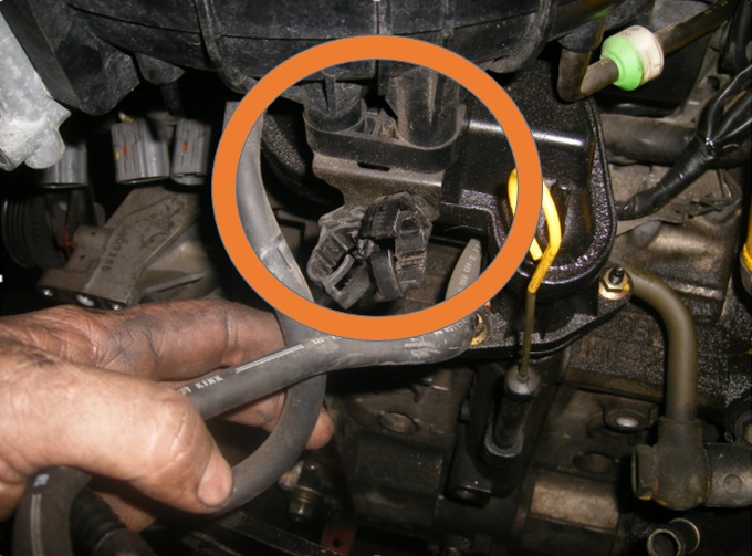
Follow this DIY for removing the UIM and you'll see them in the back behind the oil fill neck.
https://www.rx8club.com/series-i-do-...titled-196310/
Just be careful of the screened couplers (you'll see a screen mesh inside). Don't want to damage those screens.
Might want to take a picture of the AEM intake layout so you know which pipe sections go where (even better, label them as you take them out).
Also in that link I sent you above, I instruct how to remove the UIM, but a little further down in post #5 wcs added to my instructions with pictures.
Last edited by Jon316G; Oct 24, 2016 at 03:18 PM.
Registered
Joined: Sep 2015
Posts: 35
Likes: 1
Tried, ran in to trouble, the diy is good either a lil omitting or confusing or i'm missing something.
I removed the bolts 3+2 on the left (facing the car), removed the blue clipped hose in the center underneath and the connector between it and oil fill cap, removed the throttle body.
Now there's something holding the UIM under the first bend (that's after the throttle body)
- my guess is 2 bolts upside down
is there a trick to this?
PS. i'm not in a garage, or even a driveway, out on the street. daylight died, and wind picked up throwing and bending the hood, so i retreated for now...
Last edited by Brooklynite; Oct 24, 2016 at 05:46 PM.
I usually just bend that bracket up to expose the bolts and then you can get a socket or wrench on it (I like using a ratcheting wrench here).
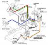
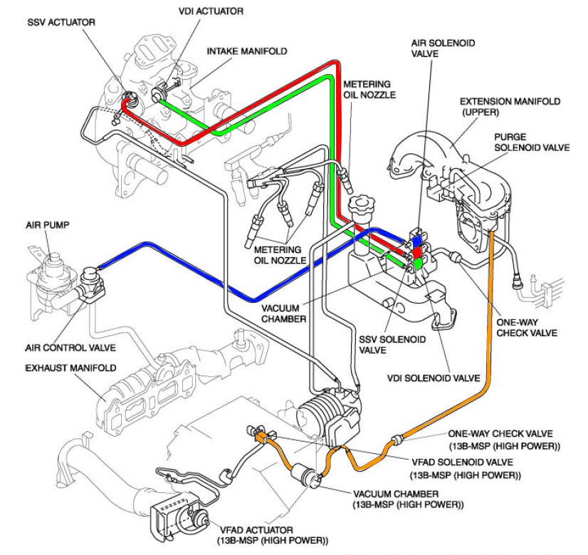
Also take care of the vacuum line behind the UIM that runs down to the vacuum chamber for the three solenoids.
In the pic above you can see it on the right with the green & white check valve.
You usually have to rotate the line back and forth on the plastic nipple to free it.
Don't grab and pull/twist on the line or the plastic nipple could break.
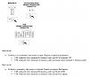
Here is good pic showing the three solenoids behind the oil fill neck:
Starting at the top is the AIR, SSV, then VDI at the bottom.
Just swap the AIR and VDI solenoid and clean the electrical contacts in the wire harness and in the solenoid in case there is corrosion on them.
FYI: All three solenoids are the same along with the VFAD solenoid if you still have that (but not used with the AEM intake like you have).
I just like to avoid the SSV in swaps since that is more critical/noticeable when it fails.
The SSV opens above 3250rpm when engine load is great enough to increase the air flow amount through secondary runners.
The VDI doesn't open until above 7250rpm to shorten the effective length of the intake tubes and provide dynamic air charging effect.
The AIR is used when the engine is started to allow the air pump to introduce secondary air into the exhaust ports, which reacts with unburnt gas and thereby raising the exhaust gas temp and enhancing catalyst activation (not needed if you are running without a catalytic converter).
Now my brain hurts.... hope this helps!
Last edited by Jon316G; Oct 25, 2016 at 07:05 AM.

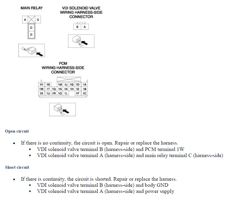
You will probably want to meter for resistance values of the VDI solenoid and check the wiring for any cuts or breaks leading to that solenoid. To properly diagnose this you will need the FSM. There's nothing you can do without it because you need the resistance values and you need the wiring diagram to trace the circuit.
If you want to take troubleshooting further you can follow this DIY I made awhile ago for testing solenoids:
https://www.rx8club.com/series-i-do-...lenoid-190364/
Solenoids can stick, but it can tell you if the valve never opens/switches.
And don't worry about tracing wires just yet.
From our experience either the solenoid itself fails or the electrical contacts become corroded in the harness and/or solenoid so start with the common stuff first.
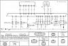
If it comes to tracing wires, you can use the diagram below:
https://www.rx8club.com/series-i-do-...lenoid-190364/
Solenoids can stick, but it can tell you if the valve never opens/switches.
And don't worry about tracing wires just yet.
From our experience either the solenoid itself fails or the electrical contacts become corroded in the harness and/or solenoid so start with the common stuff first.
If it comes to tracing wires, you can use the diagram below:

Last edited by Jon316G; Oct 25, 2016 at 07:03 AM.
Then you should see the bolt heads... it really makes the job easier.
I've tried it without bending it and it can be a pain.

Like with the other plastic nipple/fitting, it too has been known to break off if you're not careful.
Just lightly grab the hose at the nipple with pliers (I like wide nose pliers) and twist until the hose rotates.
Don't grab too hard or you'll twist and break the nipple.
Just don't rush, take your time, and all will (hopefully) go well.
Once the electrical harness is unplugged and the small vacuum line is off (caution with the plastic nipple), the solenoid will pull straight out of the manifold.
Rotate the solenoid back and forth while pulling away from the manifold.
It will be a little tough to pop out but it will.
Rotate the solenoid back and forth while pulling away from the manifold.
It will be a little tough to pop out but it will.
")

While I can't say for sure that the solenoids won't get damaged, I myself wouldn't because battery chargers usually start with high amps and ~14V+.
You can use your car battery or a 12V transformer brick from an old device you no longer use.
You can use your car battery or a 12V transformer brick from an old device you no longer use.
You can try the 12v 2a setting if you want... I wouldn't keep it energized for too long though.
And use the solenoid that was in the VDI position in case something does go wrong, that way you aren't damaging a solenoid that was likely good.
If a solenoid does get ruined, you can just install that in the AIR position and keep the good ones for the SSV and VDI.
And use the solenoid that was in the VDI position in case something does go wrong, that way you aren't damaging a solenoid that was likely good.
If a solenoid does get ruined, you can just install that in the AIR position and keep the good ones for the SSV and VDI.