Advanced Renesis tech
 11-09-2006, 11:18 AM
#176
Power!!

Another question: Could you step up the pressures though as series of pumps? You could have a lower pressure high flow pump in the gas tank and then two smaller pumps to step up the pressure in the engine compartment. One for each rotor (variable fuel pressure for each rotor) so you wouldn't have 20K PSI fuel running the length of the car and reduce your seal pressure differentials.
 11-09-2006, 11:24 AM
#177
Registered User

Join Date: Oct 2005
Location: Toronto, Canada
Posts: 2,047
Likes: 0
Received 0 Likes
on
0 Posts
That is indeed what the MS6 has. a low pressure pump and then its bumped up to 1800psi with a high pressure pump in the engine compartment, i think its right above the engine from what i learned.
________
Park Royal Condos Pattaya
________
Park Royal Condos Pattaya
Last edited by Renesis_8; 09-11-2011 at 10:35 AM.
11-09-2006, 11:34 AM
#179
Registered
Thread Starter

There are many things to consider when it comes to injector placement in a rotary. In a piston engine, you are pretty limited on where to put it. It's going to be in the vicinity of the spark plug. On a rotary, the injectors can be near the intake port way across from the apsrk plugs, right at them, or anywhere in between. The closer you get them to the spark plugs, the higher the chamber pressures get due to compression. This means you need more fuel pressure to atomize properly the closer to the plugs you get. As you move the injector towards that side of the engine, you also have less time to inject the fuel. Once you get this figured out, you still need to work out what direction the injector is sprayed as well as rotor dish shapes and fuel spray timing needed in order to get the most efficient use of the fuel injected. There's alot to worry about and much of it is far more complex than DI in a piston engine.
11-09-2006, 11:44 AM
#180
Registered User
Join Date: Oct 2005
Location: Toronto, Canada
Posts: 2,047
Likes: 0
Received 0 Likes
on
0 Posts
Hmm.. I think the rotary would need the injectors to be near the spark plugs, in the combustion chamber to make the most benefits. That'd lower the surface the fuel will stick to. To help with emissions and gas mileage. Those are the number one things the rotary needs right now. Maybe that is why the Mazda engineerer wants the 20,000psi of pressure so bad.
The MS6 gets quite good mileage last I checked (especially during crusing, when the motor can run in super lean burn), and its turbo-ed. I think direct injection in a NA engine will get very very good gas mileage. Very lean burning could be achieved.
________
Sh00t_In_Me live
The MS6 gets quite good mileage last I checked (especially during crusing, when the motor can run in super lean burn), and its turbo-ed. I think direct injection in a NA engine will get very very good gas mileage. Very lean burning could be achieved.
________
Sh00t_In_Me live
Last edited by Renesis_8; 09-11-2011 at 10:35 AM.
11-09-2006, 01:00 PM
#183
Power!!
Would you want to move away from a primary and secondary injector setup and more towards a parallel injector setup at different orientations or locations to get more coverage of the charge since your injecting fuel later in the cycle and have less time to mix?
 11-09-2006, 03:55 PM
#185
Registered User
Join Date: Oct 2005
Location: Toronto, Canada
Posts: 2,047
Likes: 0
Received 0 Likes
on
0 Posts
I dont know about that, but there is so much unknown to us. It really isnt as simple as piston engines. It seems to me that developing the DI rotary would need a lot of R&D budget too... There are many things to change and combinations to experiment with.
________
Marijuana Bubbler
________
Marijuana Bubbler
Last edited by Renesis_8; 09-11-2011 at 10:35 AM.
11-09-2006, 07:20 PM
#186
Registered
Thread Starter
Originally Posted by shaunv74
Would you want to move away from a primary and secondary injector setup and more towards a parallel injector setup at different orientations or locations to get more coverage of the charge since your injecting fuel later in the cycle and have less time to mix?
Speedsource Racing also alters which injectors get used on their 3 rotor race car except it isn't direct injected. The primaries are located right at the base of the manifold pointing directly into the intake port. As rpms rise, an additional set come online up by the throttleplates. They slowly handoff from the primaries to the secondaries. This supposedly increases fuel mixing.
DI has some of these things to work out and one way to do it is to raise fuel pressures up real high.
11-09-2006, 07:21 PM
#187
Registered
Thread Starter
Originally Posted by olddragger
It would seem that for di a differant combusion shaped depression could be used? .blows my mind just trying to grasp the concept/advantages. Maybe two combustion chambers to each face? Am i Crazy?
Olddragger
Olddragger
11-09-2006, 07:49 PM
#188
Registered User
Join Date: Oct 2005
Location: Toronto, Canada
Posts: 2,047
Likes: 0
Received 0 Likes
on
0 Posts
Hmm RG, I think the DISI only has direct injection injectors. The Lexus IS has both convention and direct injection. The Speed6 guys are discussing if they need to add convention injectors in the manifold once they reach the limit of the injectors, since they wont be able to find any aftermarket solutions for higher flow direct injection injectors.
________
Oliviya live
________
Oliviya live
Last edited by Renesis_8; 09-11-2011 at 10:36 AM.

 11-13-2006, 10:44 AM
#193
Banned

Join Date: Jun 2005
Location: Riverside, Ca
Posts: 188
Likes: 0
Received 0 Likes
on
0 Posts
ok now just out of curiousity ive gone to school to work on cars........however have limited information on the rotary.........ok someone had posted in earlier posts......reguarding the rotors and the dish area on them that has to do with compression ratio......since our rotorsr so much better in effect as apose to u know the older 13b rotors......would it not make since for someone to take our same design n in effect make a bigger dish area to compensate for those wanting to go FI......have good strong rotors yet also having a decrease in compression for an increase in boost. Or is there someone out there with the skills, to say if u had the cash buy an extra set of renesis rotors, n have someone use there talents n create a bigger dish area........???? just my thoughts dont wanna get flamed but i my self am goin FI soon......n if i could run a little extra boost it would be nice........especially considerin my car drinks crappy 91 CA gas.....but its V power as apose to ARCO lol if anyone can message me on what i just said n let me know ur thoughts on it........i would appreciate it.
11-13-2006, 10:47 AM
#194
Registered User
Join Date: Oct 2005
Location: Toronto, Canada
Posts: 2,047
Likes: 0
Received 0 Likes
on
0 Posts
There are many with the skills to lower the compression on the Renesis, but there isnt a market to buy them.
________
Glass pipes
________
Glass pipes
Last edited by Renesis_8; 09-11-2011 at 10:40 AM.
02-13-2008, 09:43 AM
#195
Registered
Hello everyone!
I�m bringing back this old thread because I think it�s a real shame that such an amount of great technical information gets lost.
A little more than one year ago, here, there were speculations about possible performance increases of the current renesis, as well as an interesting discussion about direct injection for the rotary. I think that the creation of the 16x could be an interesting point to start this discussion once again.
On top of that, I�d like to add a couple of things that had been floating in my mind:
First of all, I�ve been thinking about the feasibility of a hybrid intake and exhaust system for the rotary. As we know, side ports are very good at precisely controlling the airflow of gases going in and out of the engine at lower speeds, whereas peripherial ports allow an engine to reach very high peak power numbers. So the idea would be this, have an engine with both side and peripherial ports, with butterfly valves used to select only the most effective gas paths for every condition.
I think that such a thing was attempted several years ago by Mazda for a competition 10A engine (a butterfly valve was used to select between a side and a peripherial intake port), but no road engine ever did this as far as I know.
Going on with this reasoning, I don�t see great problems in doing the intake the way I described.
The real problems come from the exhaust, particularly when it comes to creating a valve able to stand the heat of the exhaust stream. And on top of this, this valve would also run the risk of being clogged by carbon deposits.
For this second problem, I thought that the valve could be operated whenever possible, so that it would �sweep� its seat free of carbon: during deceleration this valve could be cycled several times and, for example, every few minutes of low load operation the valve would be quickly opened and closed, causing only a minimal power loss and providing the already mentioned sweeping action.
The more I think about it, the more I feel it�s a feasible and good idea. If someone can think a reason other than cost or marketing constraints that forbade this solution from being adopted in a production car, I�d be curious to know.
The second point is more radical. It is all based on a single question: must the apex seals be straight?
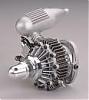
To understand what I mean, take a look at the (very crude ) rendering I did of a standard rotor (the one to the right, without the red pieces) versus one with curved apex seals (the one with the red pieces). You should see what I mean with �curved� vs. �straight� apex seal.
So, after the �what� section, you�d expect the �why� section; however, before that, I have to go to the �how� section.
As some may already have imagined, such curved apex seals would not work with a standard housing. They would need a new, grooved, housing.
The fact is that, since the angle at which the apex seals are with respect of the housing surface does vary, the groove on the housing cannot have the same depth everywhere. It�ll have to be deepest where the seals are perpendicular to the housing surface and flatter elsewhere.
And here comes the �why�: the housing groove would have to be deepest, among other places, right where the minor axis of the throchoid is, that is between the spark plugs. In other words, it would form a channel for the gases to pass, while in the current design the gases are forced to pass this �chokepoint� using the rotor recess. And, in turn, this is why increasing the compression ratio with a straight apex design (that means making the recess smaller) beyond 9:1 does not bring appreciably more power.
On the other hand, the housing groove on a curved apex design would provide the same passage area while allowing higher compression ratios.
In fact the deepest groove area between the spark plugs is surrounded by the shallowest groove areas immediately above and below it. This means that at TDC the chamber volume will still be small.
Conversely, the BDC positions will use housing areas with deep grooves (the areas near the major axis of the throchoid), thus increasing chamber volume.
Also, the more rounded shape of the combustion chamber might help with the heat loss problem.
Just like with the eccentricity of the housing, it will be possible to choose how much curved the apex seals will be, going from a nearly straight design to a heavily curved one. Of course the optimal bend radius would be determined after several experiments.
I know, it�s a very radical modification, but, at least to me, it seems it would be effective. Does anyone know if such a thing was ever attempted before?
Opinions?
P.S.: I hope that what I wrote was understandable . Writing such things in a language that is not your own is not that easy!
I�m bringing back this old thread because I think it�s a real shame that such an amount of great technical information gets lost.
A little more than one year ago, here, there were speculations about possible performance increases of the current renesis, as well as an interesting discussion about direct injection for the rotary. I think that the creation of the 16x could be an interesting point to start this discussion once again.
On top of that, I�d like to add a couple of things that had been floating in my mind:
First of all, I�ve been thinking about the feasibility of a hybrid intake and exhaust system for the rotary. As we know, side ports are very good at precisely controlling the airflow of gases going in and out of the engine at lower speeds, whereas peripherial ports allow an engine to reach very high peak power numbers. So the idea would be this, have an engine with both side and peripherial ports, with butterfly valves used to select only the most effective gas paths for every condition.
I think that such a thing was attempted several years ago by Mazda for a competition 10A engine (a butterfly valve was used to select between a side and a peripherial intake port), but no road engine ever did this as far as I know.
Going on with this reasoning, I don�t see great problems in doing the intake the way I described.
The real problems come from the exhaust, particularly when it comes to creating a valve able to stand the heat of the exhaust stream. And on top of this, this valve would also run the risk of being clogged by carbon deposits.
For this second problem, I thought that the valve could be operated whenever possible, so that it would �sweep� its seat free of carbon: during deceleration this valve could be cycled several times and, for example, every few minutes of low load operation the valve would be quickly opened and closed, causing only a minimal power loss and providing the already mentioned sweeping action.
The more I think about it, the more I feel it�s a feasible and good idea. If someone can think a reason other than cost or marketing constraints that forbade this solution from being adopted in a production car, I�d be curious to know.
The second point is more radical. It is all based on a single question: must the apex seals be straight?
To understand what I mean, take a look at the (very crude
) rendering I did of a standard rotor (the one to the right, without the red pieces) versus one with curved apex seals (the one with the red pieces). You should see what I mean with �curved� vs. �straight� apex seal.So, after the �what� section, you�d expect the �why� section; however, before that, I have to go to the �how� section.
As some may already have imagined, such curved apex seals would not work with a standard housing. They would need a new, grooved, housing.
The fact is that, since the angle at which the apex seals are with respect of the housing surface does vary, the groove on the housing cannot have the same depth everywhere. It�ll have to be deepest where the seals are perpendicular to the housing surface and flatter elsewhere.
And here comes the �why�: the housing groove would have to be deepest, among other places, right where the minor axis of the throchoid is, that is between the spark plugs. In other words, it would form a channel for the gases to pass, while in the current design the gases are forced to pass this �chokepoint� using the rotor recess. And, in turn, this is why increasing the compression ratio with a straight apex design (that means making the recess smaller) beyond 9:1 does not bring appreciably more power.
On the other hand, the housing groove on a curved apex design would provide the same passage area while allowing higher compression ratios.
In fact the deepest groove area between the spark plugs is surrounded by the shallowest groove areas immediately above and below it. This means that at TDC the chamber volume will still be small.
Conversely, the BDC positions will use housing areas with deep grooves (the areas near the major axis of the throchoid), thus increasing chamber volume.
Also, the more rounded shape of the combustion chamber might help with the heat loss problem.
Just like with the eccentricity of the housing, it will be possible to choose how much curved the apex seals will be, going from a nearly straight design to a heavily curved one. Of course the optimal bend radius would be determined after several experiments.
I know, it�s a very radical modification, but, at least to me, it seems it would be effective. Does anyone know if such a thing was ever attempted before?
Opinions?
P.S.: I hope that what I wrote was understandable
. Writing such things in a language that is not your own is not that easy!
03-12-2008, 10:11 PM
#196
Registered User

Join Date: Mar 2008
Posts: 225
Likes: 0
Received 0 Likes
on
0 Posts
On top of that, I’d like to add a couple of things that had been floating in my mind:
First of all, I’ve been thinking about the feasibility of a hybrid intake and exhaust system for the rotary. As we know, side ports are very good at precisely controlling the airflow of gases going in and out of the engine at lower speeds, whereas peripherial ports allow an engine to reach very high peak power numbers. So the idea would be this, have an engine with both side and peripherial ports, with butterfly valves used to select only the most effective gas paths for every condition.
I think that such a thing was attempted several years ago by Mazda for a competition 10A engine (a butterfly valve was used to select between a side and a peripherial intake port), but no road engine ever did this as far as I know.
Going on with this reasoning, I don’t see great problems in doing the intake the way I described.
The real problems come from the exhaust, particularly when it comes to creating a valve able to stand the heat of the exhaust stream. And on top of this, this valve would also run the risk of being clogged by carbon deposits.
For this second problem, I thought that the valve could be operated whenever possible, so that it would “sweep” its seat free of carbon: during deceleration this valve could be cycled several times and, for example, every few minutes of low load operation the valve would be quickly opened and closed, causing only a minimal power loss and providing the already mentioned sweeping action.
The more I think about it, the more I feel it’s a feasible and good idea. If someone can think a reason other than cost or marketing constraints that forbade this solution from being adopted in a production car, I’d be curious to know.
As to your hybrid exhaust ports, I would think that in addition to the carbon deposits that would surely build up on the inside of the unused port, there would also be an added level of aerodynamic inefficiency added to the chamber as it came past this lip. That'd create turbulence and probably reduce the amount of exhaust evacuated.
I was thinking along your lines, how about if you could create a hybrid port using both port types at once, 1 Peripheral connect through the housing to 1 Side Port. Rotarygod talked about the sudden pulses of the peripheral exhaust port... behind each one of these strong exhaust wave pulses there is a low pressure area (sort of like the big trough behind a large wave). If you made a peripheral port that had a smaller size than a 13B (so as to not suck out too much of the gasses in the initial burst), you could create a pulse down the pipe and connect the port to a side port immediately after the peripheral port. That way the power of the pulse from the initial peripheral blast could suck out the gases through the side port, or at least help to, especially as the rotor passes the peripheral port but the side port would still be exposed. The gasses of the side port would help fill in the pressure drop behind the peripheral wave, and allow the burn of the air/fuel more time to complete.
The second point is more radical. It is all based on a single question: must the apex seals be straight?
To understand what I mean, take a look at the (very crude
) rendering I did of a standard rotor (the one to the right, without the red pieces) versus one with curved apex seals (the one with the red pieces). You should see what I mean with “curved” vs. “straight” apex seal.So, after the “what” section, you’d expect the “why” section; however, before that, I have to go to the “how” section.
As some may already have imagined, such curved apex seals would not work with a standard housing. They would need a new, grooved, housing.
The fact is that, since the angle at which the apex seals are with respect of the housing surface does vary, the groove on the housing cannot have the same depth everywhere. It’ll have to be deepest where the seals are perpendicular to the housing surface and flatter elsewhere.
And here comes the “why”: the housing groove would have to be deepest, among other places, right where the minor axis of the throchoid is, that is between the spark plugs. In other words, it would form a channel for the gases to pass, while in the current design the gases are forced to pass this “chokepoint” using the rotor recess. And, in turn, this is why increasing the compression ratio with a straight apex design (that means making the recess smaller) beyond 9:1 does not bring appreciably more power.
On the other hand, the housing groove on a curved apex design would provide the same passage area while allowing higher compression ratios.
In fact the deepest groove area between the spark plugs is surrounded by the shallowest groove areas immediately above and below it. This means that at TDC the chamber volume will still be small.
Conversely, the BDC positions will use housing areas with deep grooves (the areas near the major axis of the throchoid), thus increasing chamber volume.
Also, the more rounded shape of the combustion chamber might help with the heat loss problem.
Just like with the eccentricity of the housing, it will be possible to choose how much curved the apex seals will be, going from a nearly straight design to a heavily curved one. Of course the optimal bend radius would be determined after several experiments.
I know, it’s a very radical modification, but, at least to me, it seems it would be effective. Does anyone know if such a thing was ever attempted before?
Opinions?
Centrifugal force acts on the air/fuel as it is rotated in the housing. With a flat apex seal, as the air/fuel is pressed against the housing evenly across the width of the rotor. Creating an even pancake. With a curved housing I imagine the combustion would probably be slowed. The fuel would probably sink into the trough, not atomizing as fully as the flat shape.
Also I'd imagine the tolerances would have to be tighter because of the seal extending out into housing, and they'd be further from the axis of the eccentric shaft and amplify the flexes of the shaft at high rpm.
Lastly, the curve would make the apex seals longer increasing the amount of friction.
Please feel free to correct any mistakes in understanding I might have about rotary function. I'm on my first rotary engine and enjoy it thoroughly, though I'm pretty revved up about getting a 16x when they hit the states (as long as it's not mounted in a CX-7 or something)
Last edited by BMonkey; 03-13-2008 at 12:08 PM.
03-12-2008, 11:00 PM
#197
Registered User
Join Date: Mar 2008
Posts: 225
Likes: 0
Received 0 Likes
on
0 Posts
The topic of heat keeps coming up in here. Especially in relation to the exhaust and the catalytic converter.
I was thinking, what if mazda created an upper exhaust manifold that included a water jacket. This way, the combustion temperatures could be raised through either more radical ignition or compression (a la fmzambon) and still be cooled to the point of equalling an Otto cycle at the catalytic converter.
The manifold would only need to be like 8" out of the ports and could bolt up with a metal gasket. Then from there, a more traditional tube unit could carry it down to the cat. Also, since the exhaust would be undergoing rapid cooling and slowing, the pipe diameter would have to be kept small to maintain exhaust velocity to an adequate level.
The water from the manifold would probably need to be run through it's own heat exchanger at the front of the vehicle before being re-introduced into the cooling system.
However with this exhaust cooling system, I imagine that under hood temperatures would drop sharply. The cat would have more life and performance could be raised while still meeting emissions controls.
03-15-2008, 03:27 AM
#198
Registered
The topic of heat keeps coming up in here. Especially in relation to the exhaust and the catalytic converter.
I was thinking, what if mazda created an upper exhaust manifold that included a water jacket. This way, the combustion temperatures could be raised through either more radical ignition or compression (a la fmzambon) and still be cooled to the point of equalling an Otto cycle at the catalytic converter.
The manifold would only need to be like 8" out of the ports and could bolt up with a metal gasket. Then from there, a more traditional tube unit could carry it down to the cat. Also, since the exhaust would be undergoing rapid cooling and slowing, the pipe diameter would have to be kept small to maintain exhaust velocity to an adequate level.
The water from the manifold would probably need to be run through it's own heat exchanger at the front of the vehicle before being re-introduced into the cooling system.
However with this exhaust cooling system, I imagine that under hood temperatures would drop sharply. The cat would have more life and performance could be raised while still meeting emissions controls.
I was thinking, what if mazda created an upper exhaust manifold that included a water jacket. This way, the combustion temperatures could be raised through either more radical ignition or compression (a la fmzambon) and still be cooled to the point of equalling an Otto cycle at the catalytic converter.
The manifold would only need to be like 8" out of the ports and could bolt up with a metal gasket. Then from there, a more traditional tube unit could carry it down to the cat. Also, since the exhaust would be undergoing rapid cooling and slowing, the pipe diameter would have to be kept small to maintain exhaust velocity to an adequate level.
The water from the manifold would probably need to be run through it's own heat exchanger at the front of the vehicle before being re-introduced into the cooling system.
However with this exhaust cooling system, I imagine that under hood temperatures would drop sharply. The cat would have more life and performance could be raised while still meeting emissions controls.
This could be an interesting idea, provided one has enough cooling capacity available. This is the real problem IMHO, getting enough cooling capacity.
After all, even in the current renesis, the exhaust runners are surrounded by water passages, so a simplified version of your idea is already in action.
Furthermore, the warmup phase could not be altered: a secondary water pump (or even a simple thermostat) could be used for the exhaust cooling circuit, and this pump could only be switched on after the catalyst has reached operating temperature.
By the way, as far as I understand it, a higher compression ratio would result in a naturally lower exhaust gas temperature, due to the greater amount of heat that's converted into useful work during the expansion phase overwhelming the higher initial combustion temperature. But I may be wrong on this point
Just one more thought about my curved apex idea and your point about the fuel concentrating in the trough: couldn't this concentration be used to create a stratified charge engine? I mean, the spark plugs are palced along the middle of the groove, exactly where the fuel tends to concentrate. This sould mean that even a low amount of injected fuel would produce a mixture around the spark plugs that's rich enough for ignition. Better fuel consumption is my next thought...
03-15-2008, 10:42 AM
#199
Registered User
Join Date: Mar 2008
Posts: 225
Likes: 0
Received 0 Likes
on
0 Posts
Just one more thought about my curved apex idea and your point about the fuel concentrating in the trough: couldn't this concentration be used to create a stratified charge engine? I mean, the spark plugs are palced along the middle of the groove, exactly where the fuel tends to concentrate. This sould mean that even a low amount of injected fuel would produce a mixture around the spark plugs that's rich enough for ignition. Better fuel consumption is my next thought...
This is like the gas particles (people) and the food (air). Without being in the midst of the air, the fuel won't combust. This is why you hear them going on about fuel atomization (making the finest mist possible) all the time in relation to fuel economy. That's why GDI with the piezo injectors are such a big deal because fuel pressure goes up from the low 100 psi range (120 psi was about the limit) to anywhere from 200 (as seen in the 3.0L BMW twin turbo N52 motor) to 4000 psi in an injector that is 5 times as fast as a standard fuel injector. Plus by putting the injector directly into the combustion chamber, you can run a wider angle spray than in the inlet, making the air/fuel mixture homogenous across the entire rotor. Also, by injecting fuel straight into the chamber at the start of compression, you give the fuel less time to heat up, thereby increasing lowering charge temperatures before ignition. Lower charge temperatures means more compression can be achieved without risk of detonation, more compression means faster flame fronts and more complete combustion before reaching the exhaust ports. Better fuel economy for everyone.
Does that help?
Last edited by BMonkey; 03-15-2008 at 10:50 AM.
03-15-2008, 11:08 AM
#200
Registered
I understand what you mean, but I was looking at this situation the other way round. That is, if there is very little total fuel in the mixture, then this concentration could be useful, instead of a problem.
If this amount of fuel were evenly distributed in the whole chamber, the resulting mixture would be way too lean to be ignited (reliably) by a spark plug.
This concentration would make the mixture (locally) rich enough for ignition. That's what I meant, if it makes any sense at all
If this amount of fuel were evenly distributed in the whole chamber, the resulting mixture would be way too lean to be ignited (reliably) by a spark plug.
This concentration would make the mixture (locally) rich enough for ignition. That's what I meant, if it makes any sense at all