When you click on links to various merchants on this site and make a purchase, this can result in this site earning a commission. Affiliate programs and affiliations include, but are not limited to, the eBay Partner Network.
Pretty much every IWG Garrett I ever tuned on one of these has had boost creep, which varies from mild to extreme depending on how free flowing the rest of the system is. Extreme porting of the wastegate helps a lot but doesn't eliminate the issue completely. It was actually partly because of this that I came up with the idea of restricting the APVs. https://www.rx8club.com/series-i-maj...9/#post4980242
But yeah, lowering EMAP is what's caused the issue you now have but that EMAP is still very high. For reference - mine's at around 11psi at 6000 with 10psi boost pressure.
I did tune one recently that had a 44mm EWG fitted (to a Greddy manifold) and that had the reverse issue ............ couldn't hold boost up top.
I'm not getting boost creep, I'm getting absolute oveboost everywhere due to the wastegate being held shut. Agreed that EMAP is still high but I'm not willing to go to an EWG because of too much hassle. I might as well change the entire turbo and manifold... which is $ I don't want to spend. The IWG on this turbo is about 30mm in diameter, which should be enough given the flow limitations of the T25. As said, it's either new turbo + manifold, or tone down the power expectations . I've seen enough scope of improvement with this ic/exhaust revamp that I feel it will be enough power for me.
I still have my doubts about this EMAP measurement thing. I have to try this on a NA car and stock exhaust to get a baseline reading. I recall getting 20psi EMAP at NA flow levels which already sounds impossible. Brett, when you say you get 11 psi emap at 10 psi boost, do you measure differentially across the turbine? I measure relative to atmosphere - and here is where my EMAP drop stems from(larger exhaust/free flowing mufflers).
Sadly I can no longer run NA flow levels at the moment as I used to before(probs. because of BOV position reducing flow) so I can't measure exactly how much good the exhaust part did on its own.
A very rough case would be at 4300 rpm with 10 psi = ~ 210g/s; At this flow the previous setup wanted 20 psi emap, this new one seems to be at 14psi.
But upon looking at an older video in similar RPM/boost, it seems 32psi EMAP has now dropped to 24 - which to me sounds like good return on mere low hanging fruit.
Last edited by ciprianrx8; Mar 12, 2023 at 04:33 AM.
Maybe I'm reading it wrong but In your previous post you mention that you use the BOV to vent air to help control boost ..... did you realise that all that flow has to be generated by the turbo which in turn heats the air and increases EMAP (by a LOT)? If you are recirculating the air ...none of it is being picked up by the maf as it's just doing loops.
It sure sounds like your problem is boost creep to me. If you don't believe me ............. remove the lever holding the wastegate and allow it to run fully open. Don't vent the BOV and do a run to see what boost it generates at WOT. Yes 30 mm WG should be enough with the EMAP you have, but is that the flap diameter or the hole diameter?
Re my EMAP ..... I'm just measuring gauge pressure at the turbine - not the differential. I actually use the same gauge to measure boost and swap it from one line to the other between logs.
Also ...which side of the WG are you applying boost ? It's supposed to be on the side that opens the wastegate ..... not the side that closes it.
I recall getting 20psi EMAP at NA flow levels which already sounds impossible.
Sadly I can no longer run NA flow levels at the moment as I used to before(probs. because of BOV position reducing flow) so I can't measure exactly how much good the exhaust part did on its own.
When you say NA flow levels ..... it sounds like you are venting the BOV to achieve 0 psi at the lim? If so ..... that is where the 20psi EMAP is coming from! Because your engine may be flowing NA levels but your turbo is probably flowing double that!
I've never ever used my BOV to control boost. It's ONLY opened when:
a) I need to vent boost when closing the throttle body (as god intended it to do)
b) an overboost, over-load, lean afr, egt spike, or any other dangerous condition occurs. In the past the bov could flow enough to prevent any boost buildup. Now, that's no longer the case(sadly). Opening the BOV under boost and WOT now only drops boost to 4-5 psi; this is not ideal but, hey, it's less than what was before opening it.
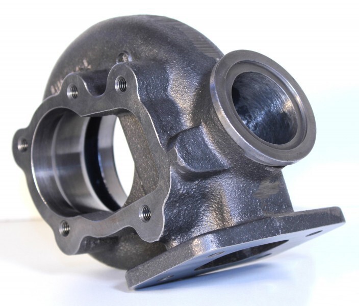
My IWG has a 30mm hole and a 40mm ish flapper. It's not something Garret OEM, but I believe it's something ATP Turbo USA cooked up for idiots like me who want to run big turbines in too small packages. My IWG actuator only has one port, so I'm sure I'm using it right as it has worked well in the past(and even struggled to keep boost up). The 20ish PSI emap at NA flow levels was gathered with IWG fully opened(no actuator present; gases free to exit via wide open IWG flapper). That sounds bad in itself but I should verify the same measurement setup with a stock NA car to confirm. I still don't know what it is I'm doing wrong in measuring this EMAP thing; 'cause I can't believe it myself what the numbers tell me.
Today I've dropped down my spring rate and reduced preload on it; now to test it again when there's time for this.
Last edited by ciprianrx8; Mar 12, 2023 at 12:20 PM.
OK .... but with all those safetys .............. are you 100% sure that the BOV is staying fully closed when there are no spikes etc ?
My BOV stuck partially open the other day ....... added a good 5psi to emap!
Well, want it or not, I have to get an EWG now. I started with a much weaker IWG actuator spring that did no difference. No boost control at all. So I've disconnected the actuator entirely and left the flap wide open.
Overboost by 5000 rpm instead of 4000.
This time my failsafe kicked in faster than I could notice(watch TPS vs BOV failsafe triggered). I've got a buzzer that goes on whenever such a failsafe happens, it was at that time that I lifted off the throttle.
Keep in mind that the same IWG was able to keep boost under 5 psi at WOT and redline before this exhaust/ic revamp.
So, lack of emap is a blessing and a curse. I have to think long and hard about if this turbo manifold I have right now can be saved somehow. Space for a 45mm EWG is very tight.
Then I see this steaming pile of **** and ask myself who thought this was a good idea:
Because if I've learned anything at all from this ordeal, is that you _never_ do the exact stuff they tell you not to:
Last edited by ciprianrx8; Mar 13, 2023 at 05:50 PM.
given how much emap there is it�s still better than nothing and will probably work. Because there�s more to it than that; the WG size and other factors matter.
it maybe highlights the real issue; you thinking at any given moment that you understand more than you actually do and charging straight ahead into the wall you�re not seeing.
In reality, given all three pipes come together in an open scroll just tapping into it there should work.
Originally Posted by TeamRX8
no you can just mimic the Brettus manifold in your own style; the front rotor and siamese exhaust port are piped from the front toward the rear. Just tie into those two and carry it rearward. They will be strongly biased to the wastegate. Maybe better than his even. You already demonstrated great courage, don�t let us or yourself down now
Which btw a full 3� system will support more hp than you�re going to make with a 3076.
.
Look at it purely from the turbo's standpoint; 20 psi EMAP for 16psi boost at about 75% of the flow levels I aim for. At full flow full power I should be at 25psi EMAP where I once was at 47psi (same measurement setup which I still don't understand what's wrong with it but seems consistent).
LE; I think I've figured it out. Whereas I'm measuring ALL the pressure my front rotor sees on the exhaust, the setup Brett seems to be using is measuring only what the turbine inlet sees, after dumping 40% of the gas flow out the wgt(that's based on an old picture from 3 years ago so don't behead me if I got it wrong or it's no longer up-to-date). Different flows, different areas, different shapes, of course it will turn out to different numbers.
I've decided to not give up yet(mostly because this seems to be the last link towards success) and fit a 45mm EWG somewhere. The turbo is surely up to it, the IC, intake and exhaust are all squared up and so is the engine still holding up after all the abuse it endured; albeit leaking oil to the point it's putting BMWs to shame.
The plan at the moment is to create a Y for the rear rotor to dump its gasses and to snake through a smaller one(space permitting) for the front rotor:
Of course the best laid out plans fail first, so once the manifold is off it's not out of the question to scrap everything and do another one.
Last edited by ciprianrx8; Mar 19, 2023 at 10:11 AM.
IC boost at 16psi with UIM boost at only 6 psi ? Am I reading that right ? If so , was that a part throttle only log?
Also ... be careful you don't favor the WG too much with a 44mm WG or you'll end up with the opposite issue - can't hold boost! A 38mm might be a better option if it looks that way.
Yes, part throttle, closed-shut bov. Not sure of wgt position, because at some point my actuator clevis slid off the wgt flapper... leaving it wide open past that. I saw back at home when wanting to move to a softer spring. At this point the IWG does little at those flow levels, just delays spool.
I doubt I'll run into no-boost-possible land again, judging that this ewgt placement won't be that great to the extent where the wgt flows too well. It should be doable and fixable with springs and a tuned EBC. I've had a look on garretts site and found this chart:
Based on my .86 turbine hot side and target flow, the wgt should flow out 160g/s which works out reasonably for a 45mm wgt, but too close for comfort on a 40mm one. I kept in mid that I don't want a screamer pipe, so as such there will be pressure at the outlet of the wgt which will limit flow.
And they further mention that "the ideal connection is at 45� with a smooth transition. Placing the wastegate at 90� to the manifold will reduce flow capacity by up to 50 percent and can cause over boosting! More reduction in flow capacity will result if the wastegate is placed at angles greater than 90�." Yeah I doubt I'll be in the most ideal placement ever; so more margin + a tougher spring that only cracks open a slight bit is what I hope will work out for me. I plan to use this routing, too, with a soft spring:
Those flow charts don't mean much other than to show the relative performance. In the real world it's all about backpressure and how well positioned it is. I got away with a 38 for years ...only reason I changed was because the G30 was so much more efficient (less emap) than the 3582.
Your system will still have EMAP at 2x IMAP or more at peak rpm so a 38 mm positioned well will do a great job. Too big and you can get resolution issues or difficulty holding boost.
Howard Coleman on RX7Club runs a 60mm and positioned the exact opposite direction of the preferred way
yet on his recent test of a Garrett G40 1.06 AR turbo he was down in the 12-13 psi boost range and had no WG control issues at all. A G40 1.06 is huge turbine housing too, higher flowing than the EFR 80 mm 1.44 AR housing. It has very little back pressure at that boost level, if any. So there’s more to these things that people looking for simple answers don’t really want to be bothered with.
.
Well yes ...there is more than one way to do things and that's a classic example of thinking outside the square.
Gotta admit I'd be skeptical if someone sugested that to me without knowing the details . But it is a huge wastegate AND my guess is he is running a screamer pipe or at the very least a separate WG exhaust . Both those things would allow some unconventional ideas to work.
I'm running a small turbo with a small A/R, with a free flowing exhaust, no intake restriction(apart from the engine itself), running a poor manifold design, with no screamer pipe or other separate plumbing AND want to run little boost. Stack these up together and the answer screams large wastegate to me, at least. If not, well, moving down is generally easier than up(ask how I know). Then again, 60mm is a an animal of a gate despite the terrible mounting seen above. The stock exhaust diameter of this car is about there, for ref.
Now about this setup still standing as a high emap one... doubt it will still be half as bad as it started. Lest we forget where I'm measuring EMAP, on this stub protruding from the front rotor:
Correct me if I'm wrong, but that pressure is caused by all the flow that exits the rotor. not dumping half of it out the wastegate then measuring what's left and feeding the turbine. In my eyes there's a huge difference in measuring turbine inlet pressure and total exhaust pressure as seen by the rotor(once wgt. starts flowing).
I'm running a small turbo with a small A/R, with a free flowing exhaust, no intake restriction(apart from the engine itself), running a poor manifold design, with no screamer pipe or other separate plumbing AND want to run little boost. Stack these up together and the answer screams large wastegate to me, .
No
To put it simply:
big turbo with low emap wanting low boost = big WG
small turbo with high emap wanting low boost = smaller WG
The higher the emap the smaller (or less efficient) the WG required .... you've already seen this when you made the IC and exhaust improvements!
that only supports my assertion to use a larger WG.
It seems as if my words are being misinterpreted. Let me come back and edit this reply to try and more accurately convey the intention and meaning of them.
������-
all I�m trying to explain is that when the WG can be properly biased, then the smaller diameter flow path it can be to serve the purpose. It still has to be properly sized to handle the excess flow requirement not being swallowed by the turbine. When the flow path can�t be properly biased, it effectively acts like a smaller diameter. To overcome that, the WG size and flow path diameter for it has to increase.
In the case of the RX7 maniold I posted the picture and example of, the WG flow path is biased in a direction opposite of the flow into the turbine. In the example, it was operating at low pressure making upper 3xx whp. So I get Brettus� point and if you go to RX7Club to the thread where the example came from, I posted the exact same thing. In reality, this situation is a bit different than over there. He�s going to be pushing that RX7 manifold to 25-30 psig boost for 600 whp or more eventually.
The reason the wrong bias works is because the oversized 60mm WG is effectively operating as a smaller size. Can a WG be too big? Sure, but it has to be way down at the bottom of the duty range for that to occur. There can be other things going on that can make it look like that�s happening, when it�s not though.
I don�t see that happening up to a 50mm WG size in this application. Especially if the flow path isn�t optimally biased to it. Because one aspect not being considered is this; this isn�t an actual Garrett turbo and assuming it�s the same as one can be a mistake. It wouldn�t be the first time a far-east, no-name turbo had 0.83 cast on the turbine housing, but in reality was a 0.65. Because based on all the numbers I�ve seen so far, it seems smaller to me than stated.
Those are just my experiences and thoughts on it. Not trying to start any argument. Frankly, not going to care past this post unless someone wants to pm me.
.
Well IMO
38mm - 40mm : will work great on this setup in the position proposed.
44mm-45mm : a bit oversized but will still work ok so long as flow is not too heavily favored towards the WG
50mm : way too big ... dumb choice unless flow is at right angles or worse (as seen in rx7 example above)
Based on ............ actually doing it myself plus tuning many Renesis systems of various configurations similar to this.
For me its just "strange" approach to use much bigger WG than to place it correctly. If correct placement is absolutely impossible, than it can be argued for...
A to big WG will be very difficult to control (small opening creates very large area and pressure change) - same like to big throttle, if at 20% opening, you flow 95% of requirements, than you are way oversized, all the resolution is in the 20%, ie it has to be 5 times more accurate (not easy to achieve). same will apply to the WG.
Intentionally putting it so it is in a very unfavorable position to flow, just creates even bigger headache. it can create all sort of control problems due to turbulence, etc.. we should strive for as linear response as possible or towards logarithmic (in regards to flow / power / rpm), while a overly large creates an inverse logarithmic (very big change in start, and than very small change as its further opened).
The RX-7 manifold should be evaluated once he is at its target level of power. Haven't seen the thread if he gives actual data (and not feelings) on how good the WG is at regulating flow / boost so don't want to comment on that in particular..
The reasons I'm so confident in my choice for a 45mm gate despite being on the large size is:
1) I've got absolute control over my EBC. Hell, that thing can have N input variables, EMAP included. The output(s) can be any PWM duty cycle at any frequency I want it to. I can also use 2 separate solenoids to apply pressure as desired to either bottom or top ports of the wastegate(though that can't be needed). Viva la hardcore DIY; given how bad my setup was/is, no commercial EBC would have done a good job. My PWM resolution can be in as little as 256 steps or as many as 32768, which, let me tell you, is much better than the OEM ECU signal feeding fuel injectors (or throttle body, for the same matter!)
2) plethora of spring combinations to use as base spring pressure, in 2 psi increments
3) depending on how fab work turns out, I may only use the rear rotor runner to feed the wgt, and bias it 50/50 between the turbo and wgt. The runner I believe is already 45mm OD. I keep running the numbers to see if one rotor shall drive the turbine and the other just be wastegated mostly. Now where did I see that before
4) still plan to run 3 very different boost levels, ranging from "none as mechanically possible", 5 psi for 98 RON gas and 10 psi for 100 RON gas.
5) still use the wgt as a backup failsafe for those 1/100 chances where I'd need to run NA or suddenly revert to NA flow levels. As said, much nicer being thrown back into NA slow realm than having to pull the engine due to an overboost or lean spike. Pushing boost up against a weak spring should do the trick. Pushing boost alongside a weak spring to keep it shut should help keep it shut for as long as needed.
Last edited by ciprianrx8; Mar 21, 2023 at 05:14 AM.
The rear port wont flow quite enough to allow proper wastegating by itself and could result in serious boost creep .... you should join front and rear as originally sketched.
Or take it from the where they all join as Team suggested.
Ciprian the 256 is not chosen by coincidence (I have been tuning with WinOLS without a2l or damos..)..
You cant control a flow of solenoid (or even throttle position), or fuel injector in higher resolution than that. Also resolution of feedback sensor is not high enough. Don't be fooled by number/resolution you can output in the sw. 5V/256 signal = 0.02V.. or for any feedback sensor, they are most often in .5-1% range of accuracy. 1/256= 0.3%. the TB would simply "round off" the input signal... etc. lets not forget mechanical "acuracy" ie, slack and tolerances.