
For those with Electronic Background....


For those with Electronic Background....
I need a simple electronic circuit that will help me accomplish what is depicted in the attached pic. This is for a more personal project but I know there is talent in this forum and I am no "wizzard" with electronics.
Basically when the switch is off I want the motor to turn in one direction indefinitely until and if it hits a stop at which point its Voltage would drop and its current would go sky high and then it shuts off (I'm guessing a current limiting or voltage drop cut off can be used)
When the switch is placed in the on position(12V) i want the motor to run in the opposite direction (reverse polarity) until and if it hits a stop at which point it shuts off again.
Any help is greatly appreciated.
Best regards,
Chris

You are better off using a 12V DC motor controller.
You'll need to find one within your voltage spec and has a current limiter installed.
This way you can adjust the limiter trip-point based on the motor and also adjust the motor speed.
You'll need to find one within your voltage spec and has a current limiter installed.
This way you can adjust the limiter trip-point based on the motor and also adjust the motor speed.
Chris
But you need a way to monitor the current and also adjust it to your motor spec.
Having the flexibility to adjust to your motor is very important since different motors have different specs.
This is archived with a logic circuit on a controller board.
Or if the motor is moving something like a car window, you can wire limit switches on both sides so that voltage is cut-off when the switch is engaged.
I know how to make a circuit that will run one direction constantly(as soon as power is connected) when there is no input and the other direction when the +12v signal comes through...I just need something to shut it off when it reaches its "destination" and cant go any further to save the motor. Oh and I need it to be able to handle this on a regular basis...its normal operation will consist of it reaching the limit.
EDIT: I though you were talkign about Low Limit Voltage switches....I see you are talking about "physical" limit switches. Its moving something rotatory about 300 degrees so limit switches are out of the question.
Any other suggestions???
Last edited by ChrisRX8PR; May 20, 2009 at 03:57 PM.

The Professor
Joined: Aug 2004
Posts: 3,479
Likes: 7
From: Omaha, NE
I'll have to think of a simple way to wire this.

Registered
Joined: Mar 2006
Posts: 101
Likes: 0
Could this be your ultimate goal? or maybe pick out what suits your application:
https://www.rx8club.com/series-i-do-yourself-forum-73/diy-auto-up-down-windows-86459/
https://www.rx8club.com/series-i-do-yourself-forum-73/diy-auto-up-down-windows-86459/
Thanks for the responses. Keep em' coming.
Chris
Thanks....I am reading lots.....hopefully I'll sort this out...
Any more ideas?
Best regards,
Chris
Thats why I recommended using a controller in the beginning.
Check this one out and see if it'll suit your needs:
http://www.electromen.com/commondata/vkem-140-12.pdf
Check this one out and see if it'll suit your needs:
http://www.electromen.com/commondata/vkem-140-12.pdf
Thats why I recommended using a controller in the beginning.
Check this one out and see if it'll suit your needs:
http://www.electromen.com/commondata/vkem-140-12.pdf
Check this one out and see if it'll suit your needs:
http://www.electromen.com/commondata/vkem-140-12.pdf
Chris
Thats why I recommended using a controller in the beginning.
Check this one out and see if it'll suit your needs:
http://www.electromen.com/commondata/vkem-140-12.pdf
Check this one out and see if it'll suit your needs:
http://www.electromen.com/commondata/vkem-140-12.pdf
Thanks.
Chris
It appears that the company's distributors are international:
http://www.electromen.com/
I'll try to find something similar that can be purchased within the US.
http://www.electromen.com/
I'll try to find something similar that can be purchased within the US.

I have a few other electrical engineers here at Rockwell who are helping me look for a good cheap controller (or alternative) for your application Chris.
Got a couple good ideas, now we are just looking for a commercially available way to purchase what we are thinking.
Not knowing fully what you're controlling is making this a little tricky, though I have an idea
Got a couple good ideas, now we are just looking for a commercially available way to purchase what we are thinking.
Not knowing fully what you're controlling is making this a little tricky, though I have an idea

Registered User
Joined: Feb 2009
Posts: 14
Likes: 0
I'll draw you up a circuit. If you can solder simple stuff(like LEDs) you'll be able to make it yourself for a few bucks with stuff you can get at Radio Shack or the like.
Is it possible for you to stick a multimeter on the motor and see how much current it draws so i can pick appropriate components?
Is it possible for you to stick a multimeter on the motor and see how much current it draws so i can pick appropriate components?
About the load.....I doubt it would draw much in operation until it hits a "wall" and stops and then it would be pretty large.... if it is one or two components that need to be changed for this you can still draw up a circuit...maybe assuming that it uses 4-5 amps in operation and with a cut off of 10-15 amps to start and I can play with the components on my end.
To all, I really appreciate your help on this, everyone has their "niche" and mine is not circuitry....(I must have slept through most of those classes in engineering school,
 )
)Best regards,
Chris
Registered User
Joined: Feb 2009
Posts: 14
Likes: 0
That would be great! I can build circuits.....I built a few ignition drivers for the RX-8 when we were experimenting before we started using internally driven coils for our ignitions.
About the load.....I doubt it would draw much in operation until it hits a "wall" and stops and then it would be pretty large.... if it is one or two components that need to be changed for this you can still draw up a circuit...maybe assuming that it uses 4-5 amps in operation and with a cut off of 10-15 amps to start and I can play with the components on my end.
To all, I really appreciate your help on this, everyone has their "niche" and mine is not circuitry....(I must have slept through most of those classes in engineering school,)
Best regards,
Chris
About the load.....I doubt it would draw much in operation until it hits a "wall" and stops and then it would be pretty large.... if it is one or two components that need to be changed for this you can still draw up a circuit...maybe assuming that it uses 4-5 amps in operation and with a cut off of 10-15 amps to start and I can play with the components on my end.
To all, I really appreciate your help on this, everyone has their "niche" and mine is not circuitry....(I must have slept through most of those classes in engineering school,
)Best regards,
Chris
I dont know what your level of component knowledge is
 so i am working on something simpler. Tell me this, would you be more comfortable/prefer building an H-Bridge from components(transistors/mosfets) or would you rather use an Integrated circuit?
H-bridge IC: (just an example, i havent looked to see if this specific IC would suit the application) http://www.national.com/ds/LM/LMD18200.pdf
Component H-Bridge:
also other things that may help or make this simpler for ya/me -
-do you happen to know if it is a worm drive? ie, once the valve reaches full open/close - is it held there by mechanical design, or via shorting/braking the motor?
- how does the motor sense full duty cycle as it is OEM? load sensing, time period, microswitch?
- can you take a MM to it? voltage and current during operation and at load spike will determine which component values to choose.
i think its probably likely that its worm drive or similar, but if by chance it has microswitches, or works off time period it will be much easier
BTW - dont go trying to build anything until i verify that i have a working simulation... electronics is a new hobby to me and i make plenty of mistakes - but i do have a very knowledgable group of peers to criticize my work. I'm thinking of throwing more transistors at it or trying inductance to shut the motor down via sensed current
FWIW the circuit using flip-flops and the comparator is a good starting point if you're comfortable with all that. You'll need to use a SPDT Return-to-center switch, try an LM311 comparator, and maybe CD4001 flip-flops(careful though as 12V on the 4000 series is pushing it!) also, the MOSFETS are 2 PMOS and 2 NMOS. This circuit can get stuck also - it would be wise to put a reset switch across the resistor at the comparator's voltage divider. If you chose to use 4000 series flip flops i'd reccomend good filter caps and transient voltage suppressor...
Last edited by needadvice; Jun 2, 2009 at 09:18 PM.
Registered User
Joined: Feb 2009
Posts: 14
Likes: 0
Breakthrough!!!!
Chris, this is likely going to be MUCH simpler than current sensing....
I took another closer look at all the manuals -
EDITAccording to the manuals is a Hall element...
position sensing is built into the motor ALREADY there is potentiometer/voltage division going on there.... with a few MM readings i can have your APV operating EXACTLY as OEM, only under your control... this is much preffered over "winging it" with load sensing i think. and it will be simpler circuit.
Sending you a PM.....
I took another closer look at all the manuals -
The position sensor is built into the APV motor.
position sensing is built into the motor ALREADY
there is potentiometer/voltage division going on there.... with a few MM readings i can have your APV operating EXACTLY as OEM, only under your control... this is much preffered over "winging it" with load sensing i think. and it will be simpler circuit.Sending you a PM.....
Last edited by needadvice; Jun 3, 2009 at 11:23 PM.
So it is for the APV motor! That is what I thought!
I have an intake manifold removed so I have easy access to the motor.
I removed the APV motor and made a DIY video on how to troubleshoot various valves on the intake manifold.
So if you need anything with it let me know.
I have an intake manifold removed so I have easy access to the motor.
I removed the APV motor and made a DIY video on how to troubleshoot various valves on the intake manifold.
So if you need anything with it let me know.
Registered User
Joined: Feb 2009
Posts: 14
Likes: 0
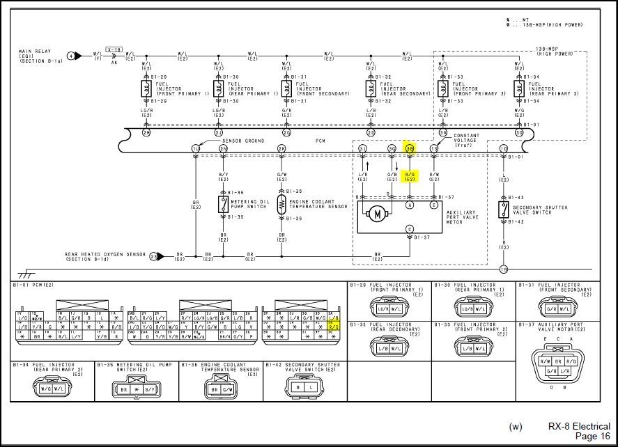
highlighted is the pin i need measurements from. should be a high/low thing. V and A during motor operation and condition that triggers shutoff. btw thats page 16 from the electrical section, pin is labeled 3B and should be Red/Green colored. If I can get V&A readings from the motor i can also choose component values for you and take all the guesswork/trial&error out of it
highlighted is the pin i need measurements from. should be a high/low thing. V and A during motor operation and condition that triggers shutoff. btw thats page 16 from the electrical section, pin is labeled 3B and should be Red/Green colored. If I can get V&A readings from the motor i can also choose component values for you and take all the guesswork/trial&error out of it
Thanks for the help.
Chris
Registered User
Joined: Feb 2009
Posts: 14
Likes: 0

Thread
Thread Starter
Forum
Replies
Last Post
JimmyBlack
Series I Major Horsepower Upgrades
273
Feb 10, 2020 10:23 PM
Olorin2
Series I Interior, Audio, and Electronics
20
Mar 13, 2016 11:01 AM