
modification of greddy manifold and downpipe


Thread Starter
life begins at 9k
Joined: Mar 2011
Posts: 54
Likes: 0
modification of greddy manifold and downpipe
I started this thread bc I needed info and pix bc their is no how to thread for this modifaction to the greddy turbo system. I started off buying the manifold and downpipe from jeff aka MM and the manifold had already been modifided with the t25/t28 flange Im not exactly sure what flange comes shipped from greddy and bc its already madified I decided to go with a garrett gt28
I wanted to go with a little bigger turbo like the 3071r but I picked up a brand new gt28 for a much better price about 1/2 of what they would normally sale for and to be honest I really only plan on shoting for around 300hp
So I put new engine in and decited to drive it a few weeks to make sure it runs and work all the kinks out. so far all good except I have to get a rear 02 o well...
I have a few questions for you guys tho I am going to go external with the waistgate im looking for the best place to have have the flange welded b4 I send it to be powder coated I have taken measurments and it looks like I got 2 options whats your input guys.
Last edited by blakerx87; May 30, 2012 at 01:25 AM.


I Can Sing....
Joined: Sep 2010
Posts: 23
Likes: 0
From: on stage
send forum member Chris a message he had a greddy manifold with a external gate on it, he might be able to show you some pictures. The places you have placed the wastegate will not work due to the engine mount placement and second picture would just have the wastegate sitting pretty low and can damage the wastegate.
Thread Starter
life begins at 9k
Joined: Mar 2011
Posts: 54
Likes: 0
send forum member Chris a message he had a greddy manifold with a external gate on it, he might be able to show you some pictures. The places you have placed the waste gate will not work due to the engine mount placement and second picture would just have the waste gate sitting pretty low and can damage the waste gate.
Ive read of a few members killing the diaphragm's in the trails because the EGT's in turbo applications.
I also need sum input on welding the cast to the ss "flange" and as far as dumping this back to the exhaust should this be ran behind the rear o2 or will this effect the car at all?
Last edited by blakerx87; May 30, 2012 at 03:28 AM.

couple of things,
I run the stock greddy turbo and currently run it with an internal wastegate. In any turbo application I would always recommend external wastegate, but with the limited space on the bottom mount greddy manifold it becomes very difficult. If you have a really good welder you may be able to have a flange mounted on the rear of the manifold and just dump it down under the car. If you are going to run external I would recommend just dumping it.
In my build thread there are pictures of how mine turned out all tig welded and smoothed. Another issue that arose that also made it easier to just cap the external wastegate idea was the cross plate that runs across the bottom of the car just behind the oil pan. When that is mounted there is very little room for a wastegate back there. If you try to go this route. You must take measurements with the motor in place and that cross member plate in place as well. Even with my manifold the way it is, there is no way we would be able to fit a wastegate on there with the cross plate bolted in. That being said if it were angled down a bit more I am sure we could easily bolt up something but it would sit very low to the ground.
The tial wastegates are ok from what I have heard (on the other hand I have also heard of them failing) but I honestly do not have personal experience with them. I would recommend the synapse as they are a great adjustable option for both BOV and wastegates.
internal wastegates are frowned upon by lots of HP chasers but for my application it is perfect. A quiet and working solution is always a good one in my book.
If you really want to bring it back into the exhaust you should try to do it post o2, The heat from it would be up there in temps and mounting it post o2 will only prolong the sensor itself.
Thread Starter
life begins at 9k
Joined: Mar 2011
Posts: 54
Likes: 0
Great info I think I'm going to go internal the next question I have is looking at the turbo i have the gt28 and comparing it to the greddy The waistgate looks to be in a different spot or diffrent angle Will I most likely have to move the arm somehow? I will up load a pix when I get home!
Last edited by blakerx87; May 31, 2012 at 08:34 PM. Reason: add
Thread Starter
life begins at 9k
Joined: Mar 2011
Posts: 54
Likes: 0
problem
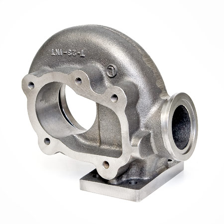
 I got a chance to test fit the turbo to the manifold and it looks as if the wg will be an easy fix the problem I am having is where to position the water/oil feeds.
 I found the instructions for the MM upgrade kit and I was using that as a reference Whats throwing me off is it looks as tho he is using the oil Feed hole as the return. Also the water inlet side is really close to the manifold. I will attach 3 pix 2 of my turbo and one of the mm upgrade.
Thread Starter
life begins at 9k
Joined: Mar 2011
Posts: 54
Likes: 0
I got a chance to test fit the turbo to the manifold and it looks as if the wg will be an easy fix the problem I am having is where to position the water/oil feeds. I found the instructions for the MM upgrade kit and I was using that as a reference Whats throwing me off is it looks as tho he is using the oil Feed hole as the return. Also the water inlet side is really close to the manifold. I will attach 3 pix 2 of my turbo and one of the mm upgrade.

Thread Starter
life begins at 9k
Joined: Mar 2011
Posts: 54
Likes: 0
Yes I plan to most def get everything coated I'm just going to test fit everything first I just want to work thru all the kinks bc this isn't the greddy turbo I'm trying to figure out how to run everything.
 I got a chance to test fit the turbo to the manifold and it looks as if the wg will be an easy fix the problem I am having is where to position the water/oil feeds.
 I found the instructions for the MM upgrade kit and I was using that as a reference Whats throwing me off is it looks as tho he is using the oil Feed hole as the return. Also the water inlet side is really close to the manifold. I will attach 3 pix 2 of my turbo and one of the mm upgrade.
Use the coolant lines that go to the throttle body.

I'm not sure what you mean about the oil feed and drain, it looks like it will work fine. Are those yoru pics? On some turbos both the oil feed port and drain looks like the drain port on a Greddy turbo.
Your problem (if those pics are your setup) will be the coolant line on the engine side. You can feed the turbo coolant by tapping into the coolant circuit that feeds the throttle body.
Your problem (if those pics are your setup) will be the coolant line on the engine side. You can feed the turbo coolant by tapping into the coolant circuit that feeds the throttle body.

From the fitting at the thermostat housing that feeds the TB, to turbo coolant inlet, from turbo coolant outlet back to fitting on the rear of the motor. That of course eliminates the coolant going to the TB. You could still go from the Turbo coolant outlet to the TB, and then from the TB to the fitting at the rear of the engine.
Thread Starter
life begins at 9k
Joined: Mar 2011
Posts: 54
Likes: 0
Ok just went to pick up some odds and ends bolts and such it appears it will be easier to use the greddy downpipe than build my own I have to make up ab a 1/2 gap from where extra flange was welded to the manifold to fit the gt2871 turbo so for clarity the manifold and d/p will sit ab a 1/2 higher than it normally would and I can make up the difference at the cat by modifying the connection.
I've been debating on rather to make this a blow thur or pull thru as i do not have the greddy pipping for the system and i will have to make my own any feed back would be appreciated. I plan on using the accessport for tunning will either way effect the outcome?
I've been debating on rather to make this a blow thur or pull thru as i do not have the greddy pipping for the system and i will have to make my own any feed back would be appreciated. I plan on using the accessport for tunning will either way effect the outcome?
Thread Starter
life begins at 9k
Joined: Mar 2011
Posts: 54
Likes: 0
Also it does not look at tho I'll be able to use the small brace that would usually not on the transmission and downpipe any disadvantage to this I suppose I could just make my own brace if need be!
I have mine set up the same way.
However, from what I have figured out, the coolant flows from thermostat to turbo to rear iron in this configuration. I am afraid that doing this can potentially warp the rear iron.
I plan on redoing mine using the coolant line that comes out from the other side of the iron (driverside) I believe it goes to the heater core.
Yes it will ... run pull through
you'll probably need this http://www.treadstoneperformance.com...yota%2C+Lexus+
Are you doing the tuning yourself?
I plan on doing this upgrade too ... but a bit different ... do you think you can post a picture of the turbo flange on the manifold? thanks!
As far as wastegate goes ... can OP use this?
Last edited by stinksause; Jun 6, 2012 at 12:30 PM.
Thread Starter
life begins at 9k
Joined: Mar 2011
Posts: 54
Likes: 0
Why pull thu? Just wondering only bc I've seen a few kits that have the blow thru and it will be a lot less pipe to run lol whats the advantages and I'll take a pix of the manifold with the modification when I get off and post it