When you click on links to various merchants on this site and make a purchase, this can result in this site earning a commission. Affiliate programs and affiliations include, but are not limited to, the eBay Partner Network.
In my old build thread I measured and proved that the Greddy manifold and turbine housing are a performance bottleneck at higher RPM, restricting the potential of the boosted Renesis. All the details of my measurements are in the other thread, but in summary, excessive exhaust manifold pressure vs. boost pressure showed the system was inefficient, and changing to higher flowing turbine/compressor wheels did not significantly improve the exhaust boost pressure ratio (EBPR), meaning the efficiency is lost in the manifold/turbine housing.
This new build consts of a low mount tubular mani connecting to a T3 turbine housing that I've put on my previous modified Greddy turbo.
Turbo Details: Similar to a Garrett GTX3576, the turbo uses a greddy/mitsubishi oil cooled journal bearing core (TD06H) with a large compressor housing (better for lower boost applications, e.g. <18psi). The original T25 internal wastegate turbine housing is replaced with a T3 twin scroll housing with no iwg. This is described as a 12cm turbine housing, which equates to 0.89 A/R - the largest AR value I could get on a T3 twin scroll for the TD06H. A Garrett GTX 76mm billet compressor wheel is used. The original Greddy 12 blade turbine wheel has been replaced with an 11 blade wheel to improve exhaust gas flow without significantly impacting spool.
Brettus and I have been chin-wagging for a while about the ultimate low-mount manifold design, and I've now decided on the method I'll use...assuming my fabrication skills are up to the task. I purchased and learned to TIG weld specifically for this project. Everything I've welded to date has just been fooling around, but I'm about ready to pop my TIG cherry. I'm going all the way with this build.
Last edited by JimmyBlack; Jan 18, 2017 at 02:25 PM.
Progress to date:
Car is jacked up on all four corners and I've pulled the midpipe and old turbo and right side engine mount.
I bolted on the new manifold flange onto the engine and found the best location for the turbo - there really aren't many options for the low mount - I managed to find a spot with the most clearance - about 0.5" from any other engine/chassis surfaces. I welded some braces between the turbo flange and engine flange to keep the orientation, then removed the flanges from the car and bolted them onto my spare motor for easier access during fabrication.
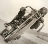
Comparing the old and new turbine housings. Inlet and outlet are quite similar, but there's a lot more surface area inside the snail for exhaust to hit and flow through the turbine wheel. Should improve the efficiency by heaps.
Temporary bracing can be seen here, holding the flanges in correct location until the pipework is in place.
Clearance is pretty tight.
Starting to mock up the pipe layout. I'm currently constructing the front runner. The central (Siamese port) runner will swing left over the top of my hand towards a wastegate located further back.
Grinding on the workbench...it's like trying to get a square peg in a round hole - working to get a nice transition from rectangular exhaust port to circular exhaust tube, while also using wedge shaped pie cuts to get the correct pipe angle. Damn, that Schedule 40 pipe is NOT easy to shape.
Oil drain is work in progress. I'll get the primaries (runners) sorted first, then use a hard drain line (I.e. pipe) to get past the primaries while maintaining some clearance.
From memory both scrolls on the turbine housing are the same size internally. The (front) scroll closest to the CHRA takes a wider path around the axis of the turbine wheel, while the rear scroll takes a tighter radius path around the axis of the turbine wheel, but from what I can see both scrolls have the same internal dimensions. I'll have a look when I'm home and if there's anything interesting I'll post up some more pics. Larger front scroll would probably suit your mani quite nicely.
Last edited by JimmyBlack; Jan 17, 2017 at 07:22 PM.
Ha, the meat grinder has scored a few busted knuckles and burnt fingers since starting. Not to cause any unnecessary concern, but my % of build completed vs. % of undamaged digits are tracking at similar rates. This build is balanced on a knife edge right now.
I'm on the fence about reducing Siamese pipe size. Smaller internal pipe volume means less volume of high pressure exhaust gas stuck in the Siamese pipe during reversion, but larger pipe volume size means promoting more airflow to towards the turbo and wastegate, making a lower pressure during reversion. Smaller pipe size may also result in boost creep.
Of course, this is all a moot point if the pipe size needs to be smaller for clearance anyway.
OMP mod is interesting. The connector was way too close to the compressor inlet pipe with my previous Greddy setup due to the larger compressor housing. If clearance is still an issue with this new setup I'll definitely get more detail from you on this mod. Depending on the nature of the mod it may be possible to encase the cables with epoxy for a robust solution.
looks like you are using the next size up pipe to what I used (mine is 11/4" schedule 10 which has a 36.7mm ID) so if you went down a size on the siamese it would be same size as what I have . Boost creep has not been an issue for me .
While I think of it , i have bolts rather than studs and nuts on the lower front two holes . You wont get it in and out on the car if you don't do that .
I could only get hold of sch40 piping, and with the thicker wall the 1.5" has 40mm ID. The 1.25" would have given me 32mm ID, which I think is too small. If I get stuck I could potentially mail order some sch10 1.5" for the Siamese runner.
The job would have been a lot easier if I'd gone with sch10 1.25"!!
My flange placement is probably a bit different to yours, so I don't think I'll have any issues clearing the engine block studs. If I do I'll try the bolt solution. Good tips, keep 'em coming!
Before welding the runners to the turbo flange I wanted to port the turbine housing/flange junction.
Before porting.
After porting.
The photos don't really show how much of an improvement the porting was. Based on the gains seen when porting my previous turbine housing, I expect this will liberate approx. 3-5whp across the range. I'll never know for sure as I don't have a before/after comparison, but I have to admit, aside from the black boogers it's a very therapeutic task.
Brettus was in town over the weekend and came around for a beer and some garage time. Was a good catch up, shame we're not in the same town more often.
I haven't made much progress with the manifold over the last week. The thick walled sch40 piping is just too thick to easily shape into a rectangle cross section where it joins the turbo and engine flanges.
After talking through with Brett, I've now decided to ditch the 1.5" sch40, and move to the slightly thinner walled 1.25" sch10. This will make fabrication much easier, and will also improve spool up, which I am a bit concerned about after moving to the T3 turbine housing.
I found a local steel supplier and will pick up the new stock tomorrow. I'm looking forward to the build getting back on track. I'm expecting to have some more updates later in the week.
Kudos for learning to weld and designing your own manifold. I can appreciate the effort and time that you're putting in as I did a fair amount of research when designing my 13B REW conversion, although I decided that I'd leave the welding to the professionals.
I did try some bashing of 1.5" Sch 10 but decided I'd be better off buying a cast flange & joiner. With your design you may be stuck with having to make one yourself; with 1.25" pipe you may struggle to get a good structure around the [T3] flange (the circumference of 1.25" pipe is a good 18mm/0.6" less than that of 1.5" pipe) and 1.25"-1.5" transitions aren't short. I'm also wary of bashing stainless for high-temperature environments; it work-hardens significantly and residual stresses are hard to relieve. I recommend you weld inside the flange and either weld or braze the outside of the pipe like the one in the image rather than cut away the pipe on the inside as you have.
Are you planning to back-purge your welds? If you aren't then I suggest that you do; the stresses from having a big lump of metal on the end may be far less than in other applications but the thermal and fatigue stresses are just as bad.
Minor update as I haven't been able to spend much time on this recently. I started again with sch10, and while I wouldn't call it easy, it's MUCH better to work with than the sch40. I'm actually making some progress now, and I've completed the front runner between engine flange and turbo flange and tacked it together. I'm really happy with the transitions and finally feel like I may be able to pull off this project. I noticed a bit of warping with both flanges, so I've straightened these out before completing the runner, so everything is very much on track right now....just going at a very slow pace.
I'll tack all the runners into place first, then back purge for the final welding.
I haven't inset the front runner into the flanges, but I may do this on the rear and centre runners when I get to them. I'd also inset them if I were concerned about strength, or if I I can't get a decent weld in the valley between the two runners where the meet at the turbo flange I may need to consider this. I'm not too concerned about strength as the turbo sits so close to the engine it's not putting too much leverage onto the manifold. I'll also have a support attached to the downpipe, which should also take a lot of stress off the manifold.
Last edited by JimmyBlack; Feb 21, 2017 at 10:51 AM.
I'm not too concerned about strength as the turbo sits so close to the engine it's not putting too much leverage onto the manifold. I'll also have a support attached to the downpipe, which should also take a lot of stress off the manifold.
Good to hear it's coming along . I don't think I've mentioned the extreme lengths my fabricator went to to support the turbo . I think it's quite important to take the burden of supporting the turbo away from a red hot stainless mani.
You'll find the stresses from differential expansion will be much higher than those from the turbo's weight and that any strengthening fillets and turbo supports will introduce additional thermal stresses and probably do more harm than good.
Professionally-made stainless exhaust manifolds on 13B REW conversions with 1.5" pipe and heavier turbos seem to be holding up pretty well despite being much longer. Designing a good manifold then building it is challenging enough as it is without adding more complications.
I don't claim to be an expert in this , but the guy that did mine builds hundreds of turbo manifolds and guarantees his work for ten years . I suspect he may have a clue as to what it takes to make a reliable manifold .
I've seen the short REW manifolds that basically mount straight off the ports and can see that perhaps these don't need much support . Anything that has a few bends and is any distance away from the ports is no doubt a different proposition.
I know it's not the same thing , but the Greddy turbo mani. is notorious for cracking . In part, I believe , due to the lack of support for the turbo.
I don't claim to be an expert in this , but the guy that did mine builds hundreds of turbo manifolds and guarantees his work for ten years . I suspect he may have a clue as to what it takes to make a reliable manifold.
I know it's not the same thing , but the Greddy turbo mani. is notorious for cracking . In part, I believe , due to the lack of support for the turbo.
I don't think we disagree. That your guy has learnt what works doesn't take away from my point that reinforcing exhaust manifolds generally does more harm than good. Without an image of your manifold (I've spent some time looking) I can't see what he's done or, more importantly, not done to learn from his work. I suspect Jimmy would like to see too.
For the Greddy manifold cracking I've similarly been unable to track down images or good descriptions. I did a fair amount of stress work a while ago so would be able to take a fair stab whether thermal or load stresses were the main factor. From a quick Google it seems that a lot of Greddy manifolds on other cars are also cracking, which suggests that Greddy's material specs and/or manufacturing processes are a big factor (in other words, you get what you pay for and Greddy didn't pay enough; casting for high temperature environments is quite tricky and/or expensive to get right).
I don't think we disagree. That your guy has learnt what works doesn't take away from my point that reinforcing exhaust manifolds generally does more harm than good. Without an image of your manifold (I've spent some time looking) I can't see what he's done or, more importantly, not done to learn from his work. I suspect Jimmy would like to see too.
I'll get a pic next time I've got the car off the ground . The bracket is attached to the manifold in a way that would allow some movement when hot yet still provide support.
Re the Greddy manifold . I had big cracking issues initially then i fitted a much stronger than stock brace to the downpipe . Didn't have anymore problems with it .