
Intercooler water sprayer


Thread Starter
Registered
Joined: Jul 2009
Posts: 425
Likes: 4
From: Whangarei, New Zealand
Here's the next project that I'm working on at the moment.
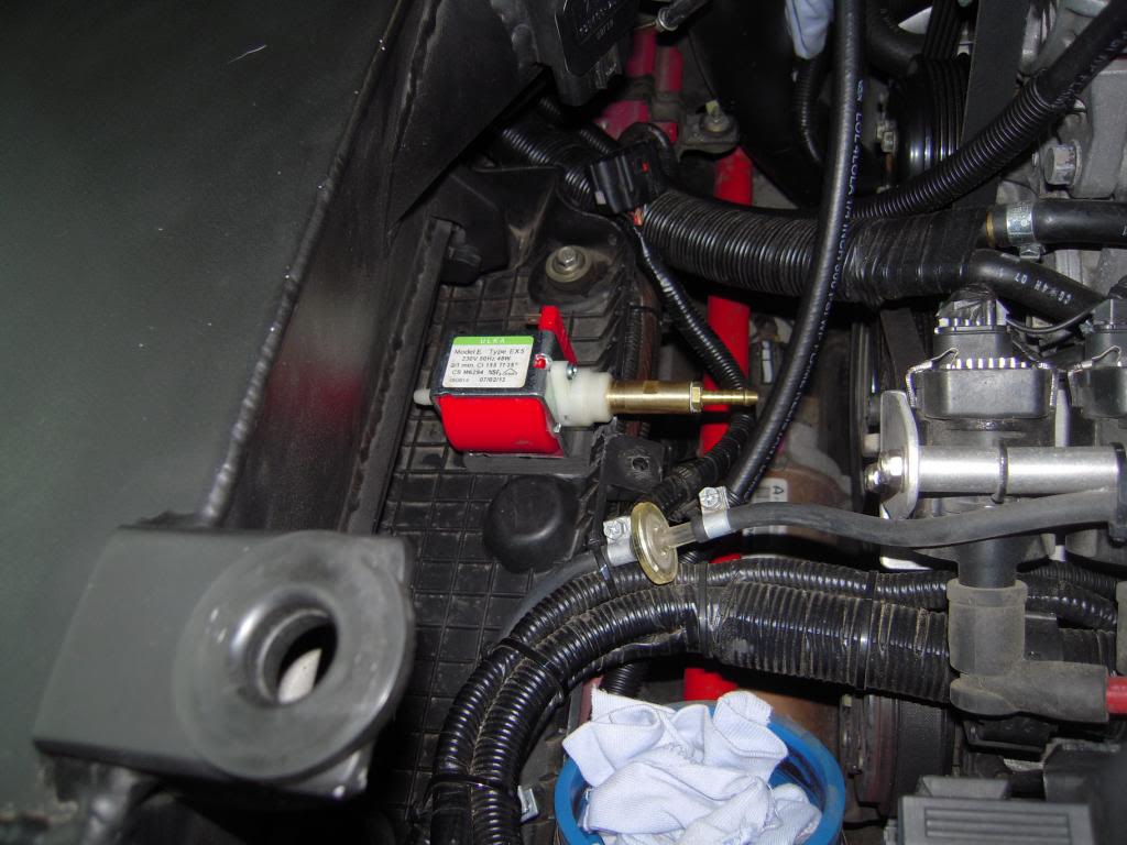
I'm adding a water sprayer ( mister ) system to my intercooler.
So far I have fitted a couple of mister nossles to the front of the intercooler.
These are a very fine nossle with filter and shut off value built into the nossle head.
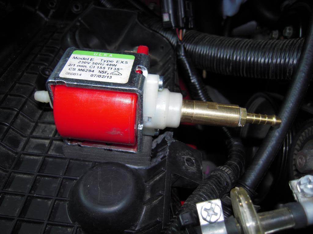
The pump I'm using is an Italian Ulka high pressure pump commonly used in coffee machines.
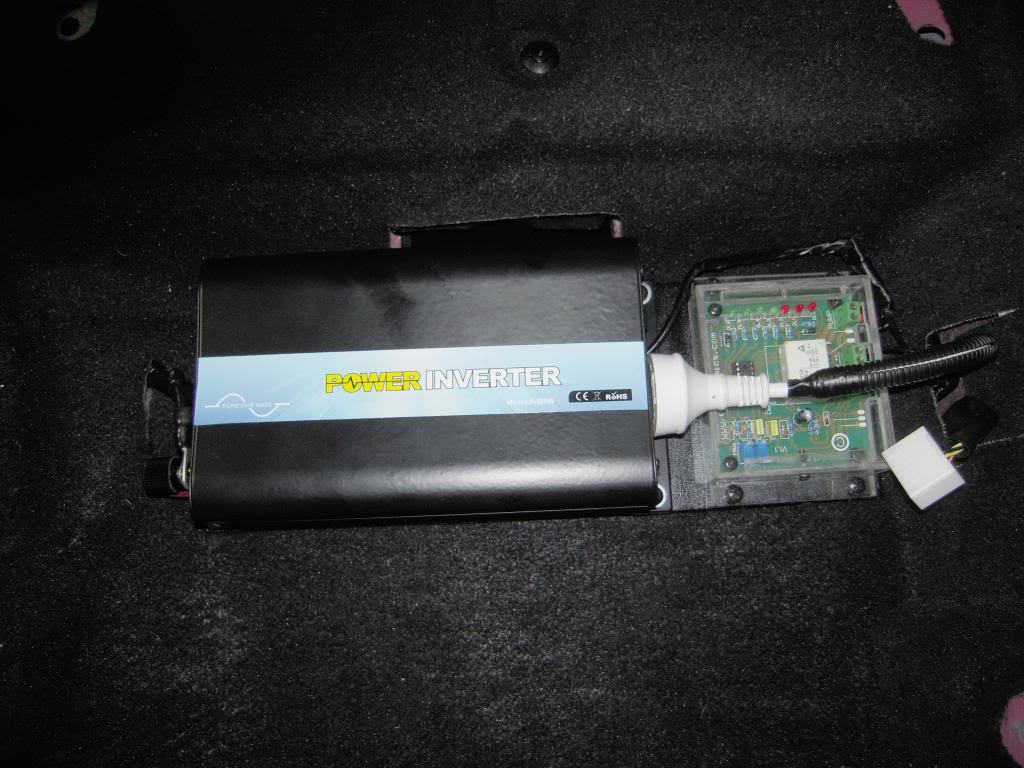
Its advantage is its very small and light and can pump up to 200psi. Its downfall is its a 220v pump, so I have to use a 12-220 volt inverter to be able to use it in my car.
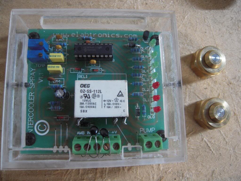
The whole system will be controlled using an intercooler spray controller circuit from e-labtronics out of Australia.
It controlls using temperature thermistors and time control.
Anyway here are a few photos of what I have done so far.
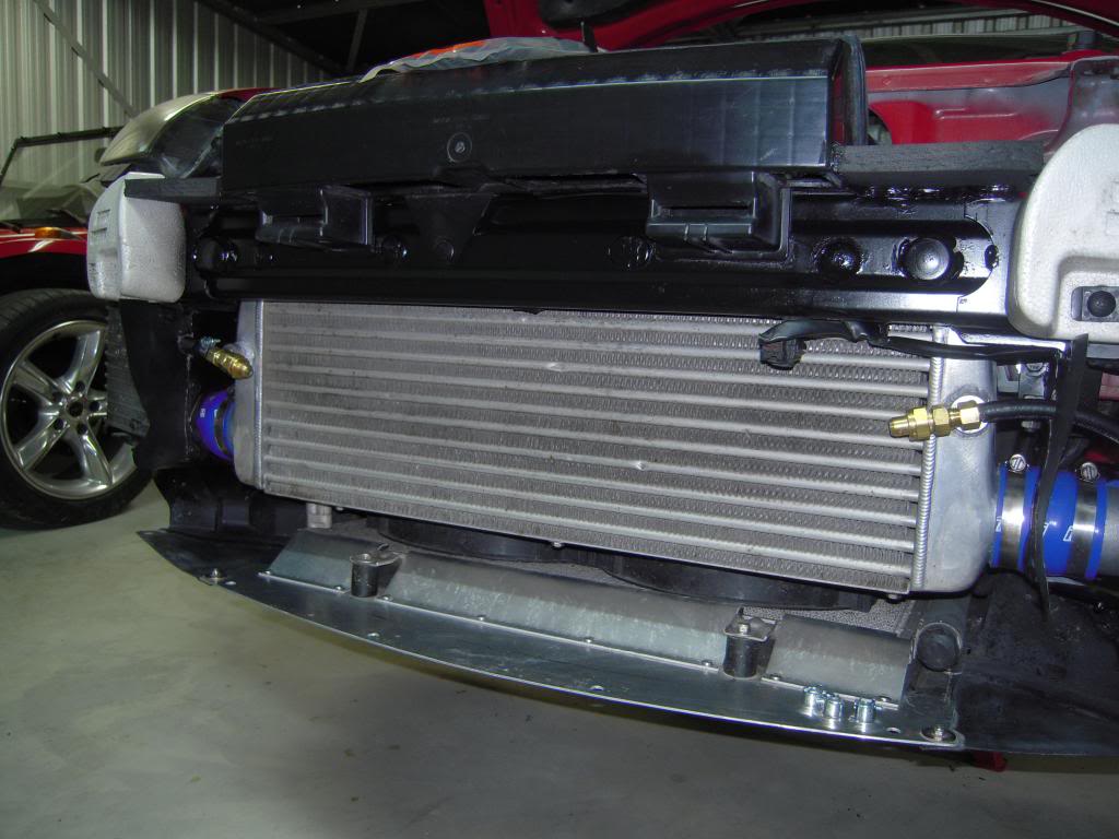
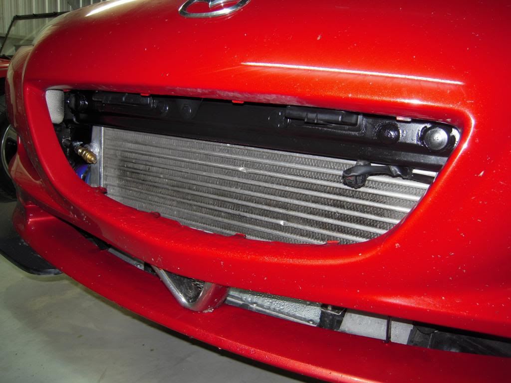
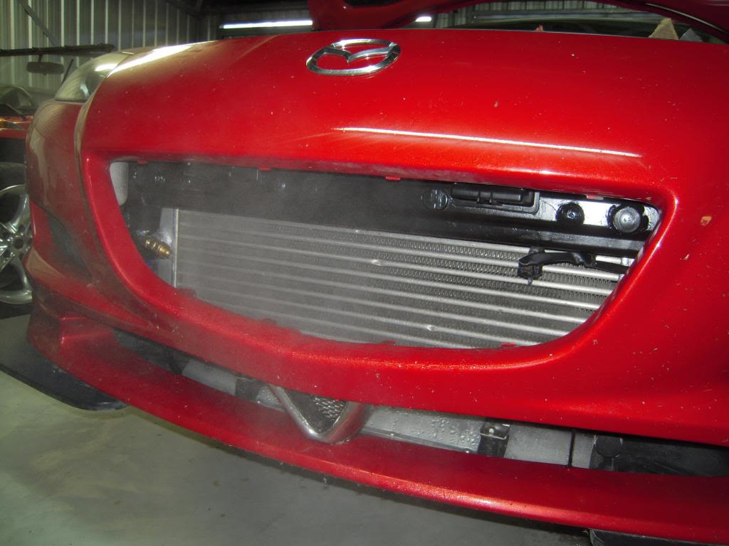
As you will see in the second and third photos, I have the grill removed at the moment and the front panel is just sitting in place while I'm doing the testing.
In the last photo you can see a test run of how the system works and the type of mist produced.
Still a lot to do yet.
Rotaman
I'm adding a water sprayer ( mister ) system to my intercooler.
So far I have fitted a couple of mister nossles to the front of the intercooler.
These are a very fine nossle with filter and shut off value built into the nossle head.
The pump I'm using is an Italian Ulka high pressure pump commonly used in coffee machines.
Its advantage is its very small and light and can pump up to 200psi. Its downfall is its a 220v pump, so I have to use a 12-220 volt inverter to be able to use it in my car.
The whole system will be controlled using an intercooler spray controller circuit from e-labtronics out of Australia.
It controlls using temperature thermistors and time control.
Anyway here are a few photos of what I have done so far.


As you will see in the second and third photos, I have the grill removed at the moment and the front panel is just sitting in place while I'm doing the testing.
In the last photo you can see a test run of how the system works and the type of mist produced.
Still a lot to do yet.
Rotaman


Thread Starter
Registered
Joined: Jul 2009
Posts: 425
Likes: 4
From: Whangarei, New Zealand
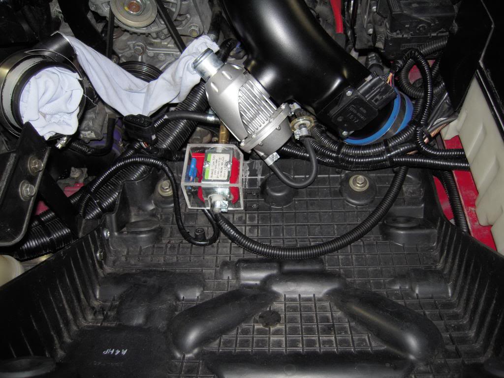
Here are 3 more photos, these are the Ulka pump which is rubber mounted in the air box tray. The second photo is with the airbox in place. The last photo is of the electronic controller and the box I made to mount it in and the two nozzles that are used to produce the mist. The nozzle hole diameter is .020in, so pretty small.
Rotaman


Rotaman

Thread Starter
Registered
Joined: Jul 2009
Posts: 425
Likes: 4
From: Whangarei, New Zealand
Thanks
I have been doing plenty of work on this project at the moment, mainly wireing at the moment, still got more to go yet.
As I do with the rest of the mods I've done, I'm trying to make all the wiring look factory, which takes hours of work. I'll try get some more photos up soon.
Rotaman
I have been doing plenty of work on this project at the moment, mainly wireing at the moment, still got more to go yet.
As I do with the rest of the mods I've done, I'm trying to make all the wiring look factory, which takes hours of work. I'll try get some more photos up soon.
Rotaman

Thread Starter
Registered
Joined: Jul 2009
Posts: 425
Likes: 4
From: Whangarei, New Zealand
I suppose it could be used on the Radiator as well if you wanted. I hadn't planed to do that at this stage.
I'm sure it would be interesting to test that idea. I will see how it goes with these two to start with.
Rotaman
I'm sure it would be interesting to test that idea. I will see how it goes with these two to start with.
Rotaman
Thread Starter
Registered
Joined: Jul 2009
Posts: 425
Likes: 4
From: Whangarei, New Zealand
Here's a bit of an update of what I've been upto with the Intercooler sprayer.
Ulka pump is now wired and all plummed up.
The electronic controller is now all wired in position along with the inverter and will sit under the passenger seat.
Still have some wiring to go, but nearly done.
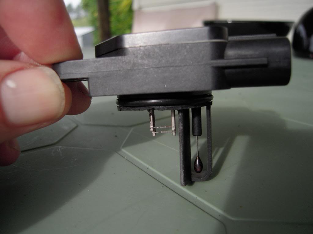
Also note that I have added a maf sensor to the inlet pipe before the trottle body, this is going to be used as my Inlet Air temp sensor and has been modified as seen in this photo.
Rotaman
Ulka pump is now wired and all plummed up.
The electronic controller is now all wired in position along with the inverter and will sit under the passenger seat.


Still have some wiring to go, but nearly done.
Also note that I have added a maf sensor to the inlet pipe before the trottle body, this is going to be used as my Inlet Air temp sensor and has been modified as seen in this photo.

Rotaman
Last edited by Rotaman; Jul 10, 2013 at 03:08 AM.


Registered
iTrader: (1)
Joined: Jun 2009
Posts: 697
Likes: 0
From: Paramaribo, Suriname ( South America )
I've noticed two things, did u use the rear rotor accent for front and is your radiator placed opposite ?
BTW, why not route the windshield washer hose to the intercooler and put a on/off valve at the windshield nozzles ?
Easier, same spray, no need for wiring or inverter ?
BTW, why not route the windshield washer hose to the intercooler and put a on/off valve at the windshield nozzles ?
Easier, same spray, no need for wiring or inverter ?
Registered
iTrader: (1)
Joined: Jun 2009
Posts: 697
Likes: 0
From: Paramaribo, Suriname ( South America )
Or why not just use a windshield washer pump ? They sell for like 20 bucks ? Or buy a washer fluid reservoir with pump for $80 ?
Just suggestions to make life easier.
Just suggestions to make life easier.


Nope - not necessary . The IAT sensor has no input into the tune so best place for it is post IC so you can monitor IATs where it matters.

I explained all that in the calc load thread . It's there to correct the max calc load curve as is baro . And we have established without any doubt, that the max calc load curve is not used for the tune - it's a safety net (for cat protection) .
I said "typically" which is a generic statement rather than specific. I don't see how that makes me wrong or having a bad week other than maybe the idea as such satisfies something within you 
If max calc load is not used as you state then why can I manipulate it to alter the calc load output which then changes where the engine operates on the fuel map under WOT/open loop even though all the engine operating conditions are still the same? I've actually done this on back-back testing. Denser air, whether baro or temp based, increases calc load which in turn puts the the engine operating in the richer area of the fuel map as was intended by Mazda since the additional oxygen needs more fuel or vice versa in the opposite scenario. Even though these inputs don't physically alter the tune they impact where in the tune that the outputs are determined.
You make many mistakes in the calc load thread and I simply chose not to pursue arguing it. In your own words (more or less as I recall) to explain your own guessing game, " Why does it do this? I don't know". It amazes me the things people make up to explain their own lack of understanding. The OE calc load based tables were specifically pushed out to 125% to account for all the input variables that could push the engine to operate there.
If max calc load is not used as you state then why can I manipulate it to alter the calc load output which then changes where the engine operates on the fuel map under WOT/open loop even though all the engine operating conditions are still the same? I've actually done this on back-back testing.
.
You make many mistakes in the calc load thread and I simply chose not to pursue arguing it. In your own words (more or less as I recall) to explain your own guessing game, " Why does it do this? I don't know". It amazes me the things people make up to explain their own lack of understanding. .
Anyway - It's great that you believe what you believe , have fun in blissful ignorance land.
Last edited by Brettus; Oct 28, 2013 at 02:54 PM.
Thread Starter
Registered
Joined: Jul 2009
Posts: 425
Likes: 4
From: Whangarei, New Zealand
I've noticed two things, did u use the rear rotor accent for front and is your radiator placed opposite ?
BTW, why not route the windshield washer hose to the intercooler and put a on/off valve at the windshield nozzles ?
Easier, same spray, no need for wiring or inverter ?
BTW, why not route the windshield washer hose to the intercooler and put a on/off valve at the windshield nozzles ?
Easier, same spray, no need for wiring or inverter ?
That accent was on the car when I bought it. My Radiator sits in the factory position, what you can see is the aircondensor sitting flat on the under tray.
The reason I don't use the windshield washer is because it is only low pressure, and will not produce the same mist quantity. This setup might be more complex and more expensive, but it should be a lot better then most.
Rotaman
Last edited by Rotaman; Oct 28, 2013 at 02:13 PM.

Driving my unreliable rx8
Joined: Oct 2012
Posts: 2,051
Likes: 7
From: Alvarado, Tx
A voltage divider requires two resisters.
One of them is the Hot wire and one of them is the Thermosister.
As temp fluctuates, the thermosister changes resistance and thus voltage output. The hot wire does the same thing based on how much cooling it is getting.
If the secondary IAT affects anything at all I do not know.

Registered
iTrader: (1)
Joined: Jun 2009
Posts: 697
Likes: 0
From: Paramaribo, Suriname ( South America )
Ok. I'll give you that on the low pressure.
How about this ? Is also 12V
12V 100PSI 4L MIN High Pressure Diaphragm Water Pump for RV Caravan Boat | eBay
How about this ? Is also 12V
12V 100PSI 4L MIN High Pressure Diaphragm Water Pump for RV Caravan Boat | eBay
Ok. I'll give you that on the low pressure.
How about this ? Is also 12V
12V 100PSI 4L MIN High Pressure Diaphragm Water Pump for RV Caravan Boat | eBay
How about this ? Is also 12V
12V 100PSI 4L MIN High Pressure Diaphragm Water Pump for RV Caravan Boat | eBay
His solution looks way overcomplicated to me. I need something simple. that is what I am aiming for. Also, you can get that Ebay pump for like $20.00 shipped.
Last edited by 9krpmrx8; Oct 28, 2013 at 04:20 PM.