
Greddy turbo - correct connection of vacuum hoses - don't stuff this up!!!!!!!!!!!!!


on the charge pipe near where it couples up to the throttle body there will be a nipple coming off for the jet air hose. My kit is an older kit thus it didnt have this nipple originally, however, the previous owner decided to weld a hidious nipple which is the wrong size too 

I have a top mount, but my jet air is hooked to the charge pipe right now, I am thinking of adding a check valve, to see if it changes anything, cant decide if intake would have more pressure then right at throttle body. It still could be a leak of sorts.

^^ I'm trying to find the drawing I had earlier with no luck; but where does the jet air hose tie into? I would Imagine that the pressure before the throttle body is always greater than the pressure in the manifold and it shouldn't matter as the direction of the pressure difference will always be away from the intake.... but i'm still looking for that damn drawing to see if I even make sense haha...
On mine its on the bottom center of the lower intake maifold.
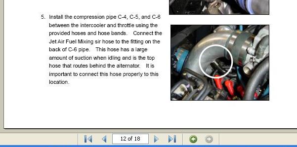
If preassure is leaking back to the throttle body, its a boost leak. If the throttle body has more pressure then your boosting the manifold directly, helping mix fuel.
I just cant decide which is the case.
If preassure is leaking back to the throttle body, its a boost leak. If the throttle body has more pressure then your boosting the manifold directly, helping mix fuel.
I just cant decide which is the case.
I'm not sure if we're saying the same thing or not but with the Jet air hose connected to the LIM, just from basic fluid mechanics there should be more pressure upstream (i.e charge pipe just before the TB) than downstream (i.e LIM) because of pressure drops (losses) in between the two locations. Meaning there should be no need for a Check valve if you have your jet air hose hooked to your charge pipe as flow will always be going from larger pressure (Charge pipe) to lower pressure (LIM). Although the difference between the two would be miniscule.
thats the basic idea, however, with running more pressure (connecting jet air to charge tube "boost") you run the risk of blowing the jet air tube off at different connections. This is what this thread is all about. be sure to either put zip ties or clamps on the connections.

Thread Starter
Boosted Kiwi
iTrader: (2)
Joined: Apr 2006
Posts: 20,845
Likes: 1,799
From: Y-cat-o NZ

Great thread Brettus, Thanks everyone.
I would just like to point out that to me ....... on my computer this picture represents the OMP hose (White stripe) being connected to where they are suggestion the Jet hose (Yellow stripe) should be connected.
I thought this was suppose to be Greddy's updated instructions lol, or it's just the picture being rendered poorly on my machine.
Love to stay and chat off to read the OMP thread by MM.

wastegate actuator to turbo outlet
took a look at the manual online. and zoomed in on it. it is yellow. haha
Great thread Brettus, Thanks everyone.
I would just like to point out that to me ....... on my computer this picture represents the OMP hose (White stripe) being connected to where they are suggestion the Jet hose (Yellow stripe) should be connected.
I thought this was suppose to be Greddy's updated instructions lol, or it's just the picture being rendered poorly on my machine.
Love to stay and chat off to read the OMP thread by MM.
I would just like to point out that to me ....... on my computer this picture represents the OMP hose (White stripe) being connected to where they are suggestion the Jet hose (Yellow stripe) should be connected.
I thought this was suppose to be Greddy's updated instructions lol, or it's just the picture being rendered poorly on my machine.
Love to stay and chat off to read the OMP thread by MM.

no sleep til it spools
Joined: Jan 2009
Posts: 502
Likes: 1
From: Austin, Texas
another thing, I connected the one way check valve hose (originally goes from the bottom of the throttle body to the to the vacuum chamber) to the nipple of the blow off valve. thoughts on this? also, there is a green sensor connected to the VFAD solenoid valve. What does this sensor read?

no sleep til it spools
Joined: Jan 2009
Posts: 502
Likes: 1
From: Austin, Texas
^^ok, so just to make sure I understand, the VFAD nipple is located post throttle body on the underside of the UIM and all I need to do is remove the check valve hose and replace it with a "regular" hose. as for the green sensor, that is safe to be unplugged as there will be no vacuum signal to send because there is no VFAD?

