
Greddy turbo - correct connection of vacuum hoses - don't stuff this up!!!!!!!!!!!!!


Thread Starter
Boosted Kiwi
iTrader: (2)
Joined: Apr 2006
Posts: 20,858
Likes: 1,808
From: Y-cat-o NZ
Greddy turbo - correct connection of vacuum hoses - don't stuff this up!!!!!!!!!!!!!
This seems to be a very common thing to get wrong and often the first thing you will notice is very poor results at the dyno .
There are two different sets of instructions for Greddy kits .
Here is an excerpt from the original instructions :
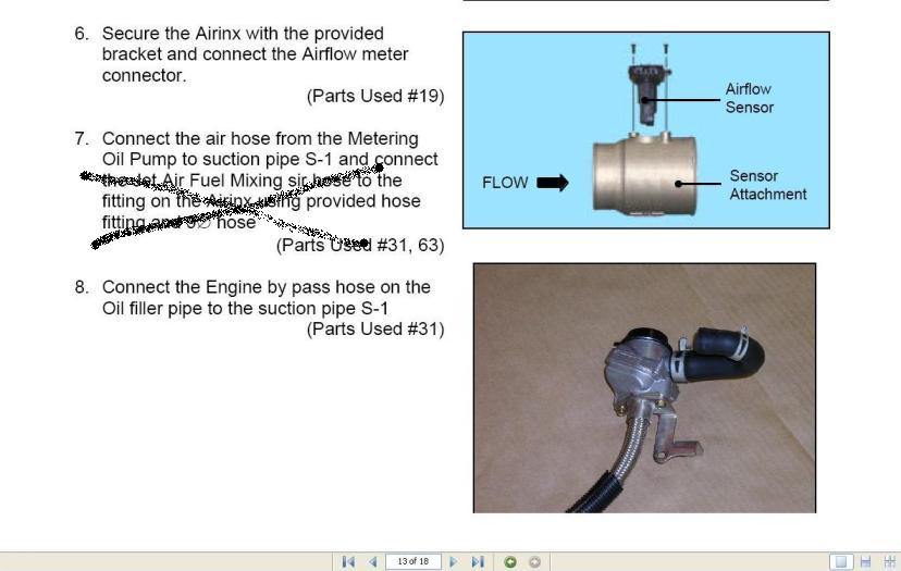
In item 7 they say to connect the Jet air to the airnx air filter connection .
This allowed boost pressure to escape to atmosphere and under vacuum allowed unmetered air to be sucked in . Bad on both counts .
Many people thought they fixed this by connecting jet air to the suction pipe(S1) instead . This is also WRONG as boost can still leak back into the intake robbing you of power .
The way to fix this is to put a ONE WAY check valve between the jet air and the suction pipe (S1) fitting such that the jet air can still suck in (metered)air under vacuum but will not allow boost to escape.
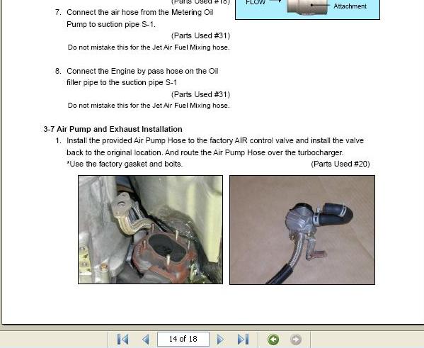
Alternatively , if you have the newer version kitset, you just hook up the jet air as explained below . However this way exposes the jet air connections to higher boost levels than the check valve method above. So if you do this , it is imperitive that you fit zip ties to all the connections on this hose. There are 4 connection points make sure you fit 4 zip ties . The hose by the thermostat is know to blow off quite easily if not secured .
And hook up the other two hoses as explained below :
Additional notes :
1/Make sure the Jet air hose and OMP hoses are correctly identified - there are marks on the end of each hose that tell you which is which - see post #10 in this thread for details . If in doubt trace each hose to its destination to be 100% sure .
2/Rather than have oil from your breather gum up your intake system - a better idea is to fit a catch can on the oil breather . Either vented to atmosphere or back to the suction pipe (S1) .
3/2006 models onwards have a different setup for the oil breather system . DO NOT leave this system in place . You MUST block off the two nipples on the lower intake manifold and connect the hose from next to the dipstick to the catch can or block it off.Then connect the oil breather line to suction pipe(S1) or fit a catch can as described below .

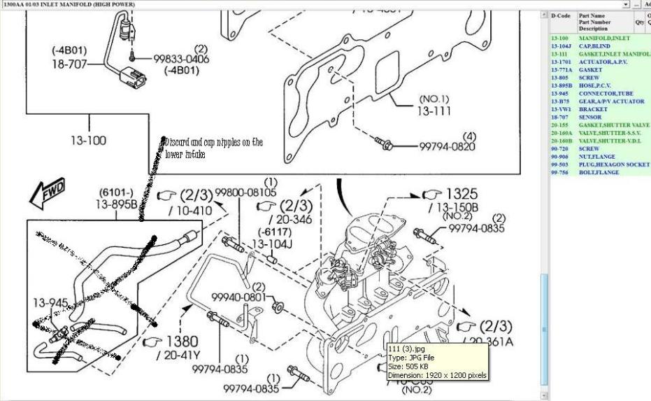
Failure to do this will give you a very large boost leak . I have seen 50whp lost at the dyno as a result .
There are two different sets of instructions for Greddy kits .
Here is an excerpt from the original instructions :
In item 7 they say to connect the Jet air to the airnx air filter connection .
This allowed boost pressure to escape to atmosphere and under vacuum allowed unmetered air to be sucked in . Bad on both counts .
Many people thought they fixed this by connecting jet air to the suction pipe(S1) instead . This is also WRONG as boost can still leak back into the intake robbing you of power .
The way to fix this is to put a ONE WAY check valve between the jet air and the suction pipe (S1) fitting such that the jet air can still suck in (metered)air under vacuum but will not allow boost to escape.
Alternatively , if you have the newer version kitset, you just hook up the jet air as explained below . However this way exposes the jet air connections to higher boost levels than the check valve method above. So if you do this , it is imperitive that you fit zip ties to all the connections on this hose. There are 4 connection points make sure you fit 4 zip ties . The hose by the thermostat is know to blow off quite easily if not secured .
And hook up the other two hoses as explained below :
Additional notes :
1/Make sure the Jet air hose and OMP hoses are correctly identified - there are marks on the end of each hose that tell you which is which - see post #10 in this thread for details . If in doubt trace each hose to its destination to be 100% sure .
2/Rather than have oil from your breather gum up your intake system - a better idea is to fit a catch can on the oil breather . Either vented to atmosphere or back to the suction pipe (S1) .
3/2006 models onwards have a different setup for the oil breather system . DO NOT leave this system in place . You MUST block off the two nipples on the lower intake manifold and connect the hose from next to the dipstick to the catch can or block it off.Then connect the oil breather line to suction pipe(S1) or fit a catch can as described below .
Failure to do this will give you a very large boost leak . I have seen 50whp lost at the dyno as a result .
Last edited by Brettus; May 6, 2011 at 05:00 PM.
Thread Starter
Boosted Kiwi
iTrader: (2)
Joined: Apr 2006
Posts: 20,858
Likes: 1,808
From: Y-cat-o NZ
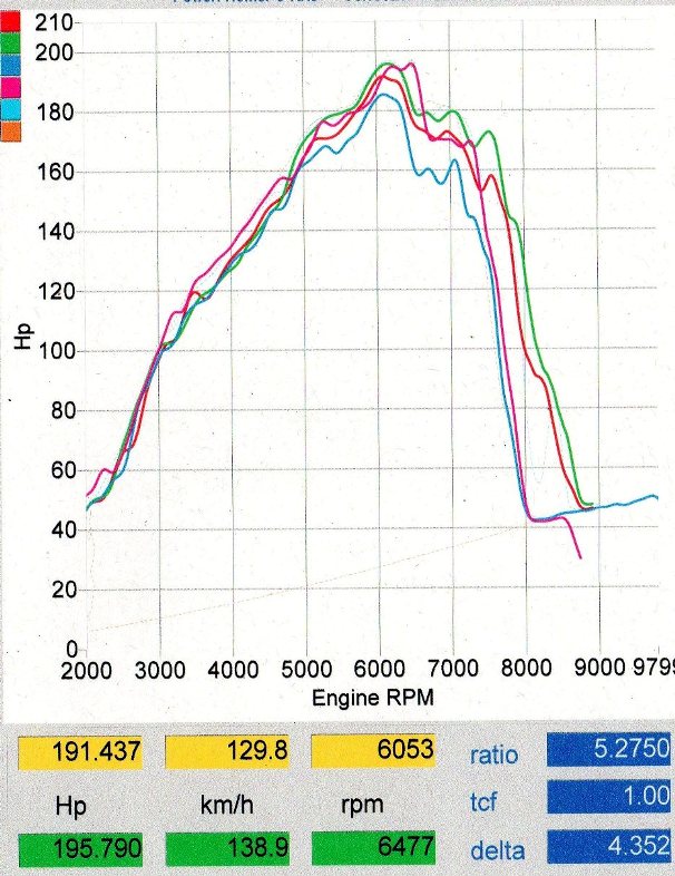
Here is an example of a very poor dyno at 5-6 psi on a 2005 RX8 with BNR upgraded Greddy kit fitted .
Issue here was that the LIM was hooked directly into the suction tube (S1) allowing a huge boost leak to rob power .Also the jet air was hooked up per original instructions with no check valve.
The same kit properly set up should produce around 240whp at that boost level .
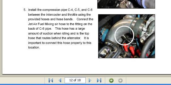
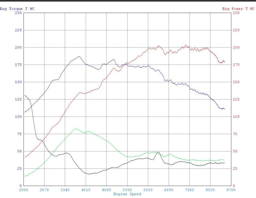
Here is an example (BNR Greddy again) where the breather tube was hooked direct into the charge pipe (the one with the white circle around it in post #1) instead of into a catch can .Also the jet air tube was hooked up per the original instructions with no check valve ..... 220 whp would be realistic at the boost level shown (4psi) but you can see it was making a lot more boost early in the rpm range . The drop in boost was related to another issue however .
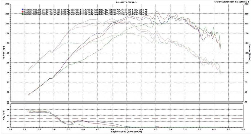
Here is a 3071 where the jet air hose had blown off under the thermostat . Should be making 300whp at 10psi , instead - this :
I have seen lots of examples of similar looking dynos on this forum , but these are the only three thus far where I have managed to talk to the owners directly to find out what was going on .
Issue here was that the LIM was hooked directly into the suction tube (S1) allowing a huge boost leak to rob power .Also the jet air was hooked up per original instructions with no check valve.
The same kit properly set up should produce around 240whp at that boost level .
Here is an example (BNR Greddy again) where the breather tube was hooked direct into the charge pipe (the one with the white circle around it in post #1) instead of into a catch can .Also the jet air tube was hooked up per the original instructions with no check valve ..... 220 whp would be realistic at the boost level shown (4psi) but you can see it was making a lot more boost early in the rpm range . The drop in boost was related to another issue however .
Here is a 3071 where the jet air hose had blown off under the thermostat . Should be making 300whp at 10psi , instead - this :
I have seen lots of examples of similar looking dynos on this forum , but these are the only three thus far where I have managed to talk to the owners directly to find out what was going on .
Last edited by Brettus; Oct 8, 2014 at 04:31 PM.

Ah great reminder brettus...I'll have a look at the markings on the hoses and let you know what they are....as for my kit I luckily have the newer set-up and a 2004... Dyno to come in the spring

Thread Starter
Boosted Kiwi
iTrader: (2)
Joined: Apr 2006
Posts: 20,858
Likes: 1,808
From: Y-cat-o NZ
That should not be a problem . In fact I would say it's the best place to hook the WG line into as you will make a little more boost that way (as opposed to straight off the end of the turbo) .
Yeah I got the Idea from you originally haha, accounts for all the losses through out the IC, hard piping, etc...
Thread Starter
Boosted Kiwi
iTrader: (2)
Joined: Apr 2006
Posts: 20,858
Likes: 1,808
From: Y-cat-o NZ
heh . Just make sure that line is well secured and protected . If it comes off it could cost you an engine .
Last edited by Brettus; Feb 14, 2011 at 09:10 PM.
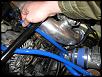
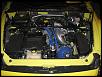
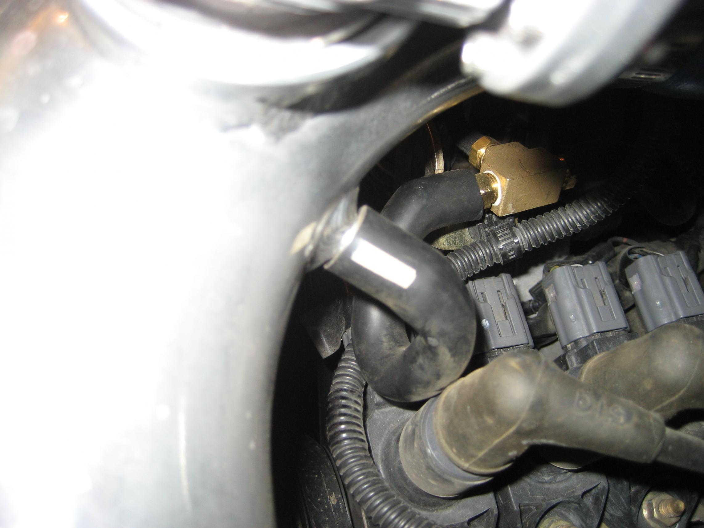
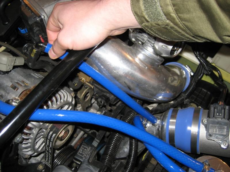
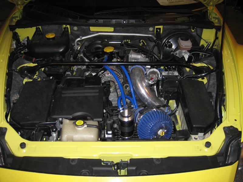
So here are some pics and hose color markings as promised. I'm not sure if all 8's are the same but for my car the Jet Air Hose was marked with a yellow patch on it and the air hose from the OMP is marked in a white patch. The oil filler breather hose is quite obvious and you should have no trouble finding this one. (It is the blue hose in the picture between the oil filler neck and oil catch can) See the pictures below for a visual. Also you can see the brass T-Fitting I used to tap my wastegate signal from the jet air hose (white marking) with.
This Picture is an incorrect photo.... you can see the White patch meaning it is the hose from the OMP:
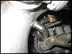
In this picture you can see the yellow marking indicating that this line is the Jet Air hose:
Oil Filler Breather:
This Picture is an incorrect photo.... you can see the White patch meaning it is the hose from the OMP:
In this picture you can see the yellow marking indicating that this line is the Jet Air hose:
Oil Filler Breather:
Last edited by RotaryMachineRx; Mar 9, 2011 at 10:34 AM.
Thread Starter
Boosted Kiwi
iTrader: (2)
Joined: Apr 2006
Posts: 20,858
Likes: 1,808
From: Y-cat-o NZ
On reflection , I think the check valve way is better .
Hooking into the charge pipe like that does get the desired result but it also exposes the jet air tubing to higher levels of boost , including big spikes at times on gear changes.
This (jet air) hose is only a slip on hose and the tube it slips onto on the LIM has no barrbs to hold it on . And it is practically impossible to to reach down below the LIM and put a zip tie on the connections . So in time it is inevitable that it will blow off .
Last edited by Brettus; Feb 15, 2011 at 12:44 PM.
Thread Starter
Boosted Kiwi
iTrader: (2)
Joined: Apr 2006
Posts: 20,858
Likes: 1,808
From: Y-cat-o NZ

hmmmm... wonder if I should look into this one later down the road... I am potentially buying an MM GT3071R off a forum member so might be a good time to tie that off if I end up doing that install.
I currently have it capped on this engine. You got me researching a bit more and maybe I will have to uncap it now. I use to have it routed to the charge pipe before the TB, though when I modified my piping I moved it to pre-turbo post maf with a check valve. Seems to only be necessary (if any) under vacuum conditions.
Thread Starter
Boosted Kiwi
iTrader: (2)
Joined: Apr 2006
Posts: 20,858
Likes: 1,808
From: Y-cat-o NZ
I currently have it capped on this engine. You got me researching a bit more and maybe I will have to uncap it now. I use to have it routed to the charge pipe before the TB, though when I modified my piping I moved it to pre-turbo post maf with a check valve. Seems to only be necessary (if any) under vacuum conditions.


I ended up uncapping the Jet Air line and running it pre-turbo/post-maf with a check valve. Just doing it to rule it out as a possibility for things going wrong come dyno day.

Just to clerify which one is the jet air hose?
I have on 07 and the factory has 3 hoses connected post MAF on the intake.
1-Connects to the metal fitting and goes somewhere under the lower intake. Is this the jet air?
2- Connects to the upper intake near the dipstick.
3- Connects to oil metering pump?
And lastly the oil filler breather hose goes to a T and connects to the lower intake.
For FI I am still not 100% sure what should be done with these 3 hoses and the breather.
Thanks