When you click on links to various merchants on this site and make a purchase, this can result in this site earning a commission. Affiliate programs and affiliations include, but are not limited to, the eBay Partner Network.
The clamp provides the seal. The bead just keeps it from blowing/sliding off. They’re really two separate things. Just because it slide’s off without the bead doesn’t mean it’s not sealing. Just because it doesn’t slide off doesn’t mean it’s sealing. However I do agree that this latest pic clearly shows that you either need a longer 45* ell or longer tube section.
what you’re missing in that pic is pressure on the inside trying to bellow out the coupler like a balloon.
Yeah, clearly clamp pressure contributes to the seal, and beads / rolls provide a mechanical "hold".
However, I still believe there is a dynamic at work in which the sections slide to their constraint ,i.e. to the bead /roll, as the boost builds in the system. That "expansion", even given the bellowing of the coupler (good point btw), in turn causes the components working together; coupler, clamp, and fully beaded section, to create the seal... w/ the leading edge of the clamp binding the coupler against the trailing edge of the bead.
Looks good. Crash bar needs aluminum cover plate for cosmetics.
Thanks, Team.
Agreed. I plan to minimally get a new front bumper, if not complete body kit, and will cover it then... via an aluminum plate (good idea) or mesh grill.
Fyi...Returned this filter as it did not fit. The base diameter, 5", is too thick. 4.5" is max. acceptable diameter w/out squishing it into place. So, back to the search...
AEM indicates I still have a boost leak... from ~3000 - 4000 rpm under WOT.
Below are two AEM profiles of 3rd & 4th gear pulls.
- The first from a couple of weeks ago indicates a solid pull w/ no boost leak.
- The second from today clearly indicates a boost leak / rise delay.
Note: Oddly, the leak is intermittent. I have logs showing both cases w/in 5 min. of one another.
edit: She's still quick and a blast to drive, but this indicates... there's more on the table.
- Boost leak: Walked thru and put 0.5 to 1.5 turns on coupler clamps. Seems to have improved..., but not completely eliminated the leak . More to do here...
- DP Rad. leak: Used some Bar's Leak Radiator & Heater Core Stop Leak and there h/b no coolant leaking since. T-stat is operating properly...I'll continue to monitor.
Still need to update tune since winter work, completely resolve boost leak, and fine tune my EBC since changing WG spring. Power generation meets my objectives. So, moving forward I'll just work to better stabilize afrs, and sustain torque curve higher into the rev range.
Tried a few things to resolve the persistent boost leak at the below curved section. After a few iterations...I believe I m/h converged on a solution to eliminate it.
Did a few pulls today and per the below AEM profile... it's holding 10# today. Will do a few more pulls tomorrow at ~11#. I'm hoping to resolve this w/out having a fabricator rework the section.
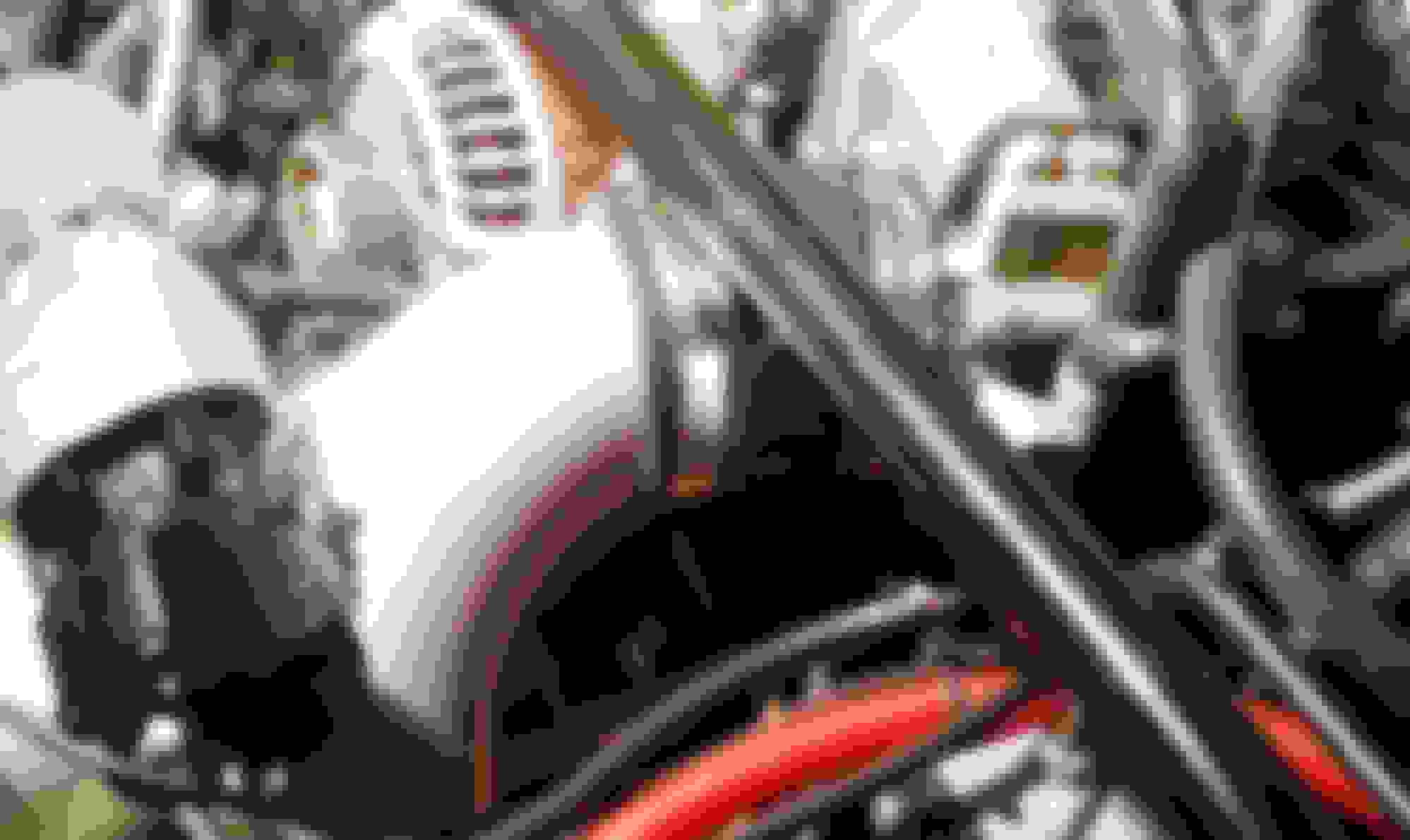
Problematic curved charge section to TB
. Clean profile ...w/ no boost leak
.
I considered it...among the things I've already done resulting in it holding ~10.5-11# pretty consistently. Above 11# it'll hold for one or two pulls ...before starting to leak again.
I'm resigning myself to the fact that the best solution is going to be adding a 2-3" straight section onto the throttle body end of the pipe w/ a nice bead. Problem solved.
Boost rise peaks at 13# and trails to 11#. I give the ave....12# for the pull.
I believe my EBC settings are fairly well sorted... and that she'll sustain torque to 8k once the leak is eliminated.
Unless the leak is really big .... I doubt it's causing that much dropoff. I still think the wastegate placement is hampering your quest for flat torque curve . In some ways it's not a bad thing as the Renesis hates high boost/flow at high rpm. If you ran say 14-15psi and allowed boost to drop away to 12-13 at peak rpm ...you would have great performance without the need to cut boost at high rpm like I do.
Unless the leak is really big .... I doubt it's causing that much dropoff. I still think the wastegate placement is hampering your quest for flat torque curve ...
You may be right. We'll see after I get this pesky leak resolved. edit: I'd say from history I can expect a ~ 1# drop when everything is sealed tight.
Originally Posted by Brettus
...In some ways it's not a bad thing as the Renesis hates high boost/flow at high rpm. If you ran say 14-15psi and allowed boost to drop away to 12-13 at peak rpm ...you would have great performance without the need to cut boost at high rpm like I do.
Interesting point. Duly noted. I'll keep that in mind once I have a reliably sound system above 11#.
Well here’s another suggestion; replace the entire elbow piece or just the elbow end only going into the TB with a 3.125” elbow to match the TB inlet OD, and instead have the transition either from the straight tube into the elbow or if you replace the entire thing then have the transition adapter coupling down where the pipe from the IC into it is. Because having that transition right at the TB isn’t helping your particular situation.
Further, do not put the BOV flange back on the TB inlet elbow. Instead locate it off the end plate of the IC outlet collector tank. Placing it in the elbow right before the TB is a common mistake not recognized by many people. It will flow better off the flat end tank connection rather than being mounted on the tube bend and then also not disturb and render the inlet flow turbulent as it’s entering into the TB. I saw Howard Coleman bring this up on RX7CLUB and it likely went over most people’s head because; as usual, they often fuss over inconsequential minutia while being completely oblivious to the obvious things that matter.
but again, just a suggestion.
.
Team, Thanks I appreciate your suggestions giving me other options to consider. And yes, ...as h/b discussed...the curved section mating at the TB is problematic.
However, I want to implement a simple, permanent solution to solve the problem at hand..., not redesign the kit.
I did consider cutting off the curved section of this pipe, and using a 90* elbow off the TB. But I prefer a 6061 curve into the TB vs. a silicone coupler elbow, and not messing w/ the bov mount, if possible, ...as it's not a present issue.
I'm considering modifying the curved section to achieve two objectives:
add an ~2" straight section to mate to the TB
ensure clearance to avoid the intake section
So I'm thinking of augmenting the existing section w/a 2" straight section out of the TB, w/as smooth & direct a path to the IC exit section connection as possible: e.g. smooth curve toward the drivers side (to clear the intake), then smooth curve downward to reintegrate into the existing charge pipe. This s/b simple, easy to fabricate and effective.
Got the TB charge section welded and the kit reassembled.
I'm pleased w/ the augmented charge section , but not a fan of the lengthy BOV recirc tube, which looks like the St. Louis Arch. Do I live w/ it or add revising it to my list of To Dos? Not sure atm...time will tell.
Functionally, the new charge section is showing promise. Drove around a bit in my limited time today and got in a few pulls at reduced boost setting. For some reason M/E was not connecting to the ECU...and I didn't have time to mess w/ it beyond the few reboots, etc. However, the below AEM boost profiles show zero boost drop from peak through the rpm range , where all previous pulls resulted in ~1 to 2 psi drop across the rpm range. Excited to see how this tighter system translates to my performance / v-dynos moving forward.
.
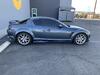
Engine bay w/ reworked charge section.
. Pull ...11.5 peak psi
. Same pull ... 11.5 ending psi, i.e. zero boost drop.


 I'll need to readdress this at some point.


 Will do a few more pulls tomorrow at ~11#. I'm hoping to resolve this w/out having a fabricator rework the section.
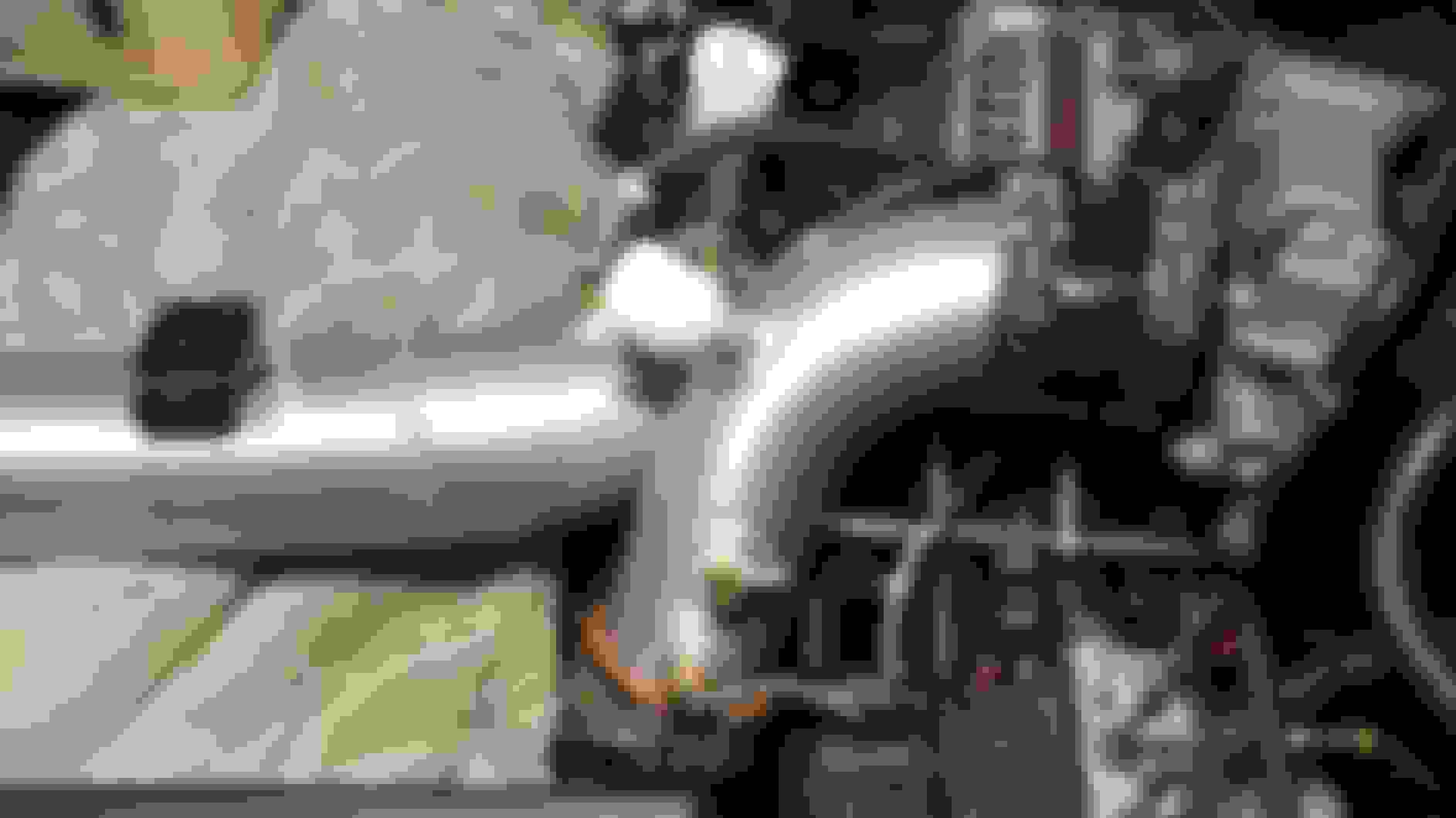


 ...
...