When you click on links to various merchants on this site and make a purchase, this can result in this site earning a commission. Affiliate programs and affiliations include, but are not limited to, the eBay Partner Network.
Looking closely, the oil cooler fins seem pretty beat up and bent over, straightening them will help a bit with the cooling.
Agreed. I need to get a fin brush and address them. That said i installed lower temp oil cooler thermostats, and my oil temps stay pegged at ~178F +/- 2F.
Agreed. I need to get a fin brush and address them. That said i installed lower temp oil cooler thermostats, and my oil temps stay pegged at ~178F +/- 2F.
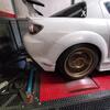
This will prob help, something I also plan to do one of these weekends. Other than the spiking after a couple boosted pulls I don't see much else wrong with your temps. My coolant temps run between 196 - 203F regularly.... on really hot days I may see 208 with the very odd peak to 210 but that's absolute worst case scenario. I don't recall the dimensions of the GReddy IC off the top of my head but I do have a bit of room under it for air to hit the rad and it is mounted flush to the bottom of the crash bar. Looking at your pics.... did you have the crash bar modified? Mine doesn't look like yours haha
My crash bar:
Last edited by RotaryMachineRx; May 10, 2019 at 09:55 AM.
This will prob help, something I also plan to do one of these weekends. Other than the spiking after a couple boosted pulls I don't see much else wrong with your temps. My coolant temps run between 196 - 203F regularly.... on really hot days I may see 208 with the very odd peak to 210 but that's absolute worst case scenario. I don't recall the dimensions of the GReddy IC off the top of my head but I do have a bit of room under it for air to hit the rad and it is mounted flush to the bottom of the crash bar. Looking at your pics.... did you have the crash bar modified? Mine doesn't look like yours haha
My crash bar:
RMRx, Thanks for chiming in and providing a sanity check. Where are you measuring your coolant temps, i.e. are those inlet or exit temps? My coolant temps indicated above are inlet. Add 8-10F for exit temps.
The bottom of your IC looks nearly ideal. Mine is ~an inch above the undertray. I believe ideally we want air thru the main opening directed to the IC, and air thru the bottom horizontal opening directed to the rad. My current IC doesn't allow that option.
Yes, during install I removed the bottom half of my crash bar to facilitate more flow to the IC.
RMRx, Thanks for chiming in and providing a sanity check. Where are you measuring your coolant temps, i.e. are those inlet or exit temps? My coolant temps indicated above are inlet. Add 8-10F for exit temps.
Measuring coolant temps from the stock sensor, so I believe engine inlet?
OMP module w/ sensor arrived. Swapped in the sensor and CEL and limp mode cleared.
We've a good rain here. So, no WOT logs, but investigating temps instead. Below are a 3-gauge dash shot and OBDII OEM gauge screenshot taken w/in seconds of one another. Couple of observations:
IATs: IAT is 11F above ambient at highway cruising. Observed a delta of ~7 - 20F depending on vehicle speed. Pleased to see that IATs drive consistently to a 7-8F above ambient during runs.
Coolant Temp: The OBDII screenshot Engine Temp measures inlet temps, while the Profec temp gauge (3-pod / middle gauge) measures exit temps.
At this moment in time inlet temps were 190F, while exit temps were ~198F. (8F delta)
Immediately after some boosted accelerations... (OEM) inlet temps measured ~ 218F, (Profec) exit temps measured 225F. ( 7F delta)
Based on this ...I'm comfortable w/ IATs, which drive downward during runs , but definitely need improved coolant system capacity...which rise rapidly during runs. So, validates my plan to increase air flow to the rad at the cost of decreasing air flow to the IC.
Good idea would be to get an aluminum under panel, make sure everything is all sealed up, and see if theres a way to improve airflow through the engine bay to lower the pressure behind the radiator and allow air to flow through significantly easier. It can be easy to overlook how air might flow through and evacuate an engine bay when doing all these modifications.
Great work on the car so far. I see the same (about 10 F) between the inlet (stock location) and outlet (in upper radiator hose).
I had a big problem with water temps with the FMIC, so I mounted it flat and have created a reverse v-mount of sorts. Water temps are no problem any more, but my FMIC is less crucial since I inject water/meth at two locations and run around 60 percent ethanol. I don't wanna step all over your post, but here is a reference of what my water temps look like during a 1/4-mile run. This was the run where I blew a vacuum line off at around 100 mph and lost power through the 1/4-mile.... Only a 9 degree rise in water temps full out for 12.5 seconds at 22 psi.....
Good idea would be to get an aluminum under panel, make sure everything is all sealed up, and see if theres a way to improve airflow through the engine bay to lower the pressure behind the radiator and allow air to flow through significantly easier. It can be easy to overlook how air might flow through and evacuate an engine bay when doing all these modifications.
Xero, Like the way you think.
My battery has already been relocated to trunk. Next up for cooling:
- Shorter IC to allow increased flow to the rad.
- Aluminium under tray w/proper ducting to the rad.
- & a tastefully vented hood
Stroker ..... I had the same issue when I had a 12" high IC but fixed that by running a 10" mounted high as possible instead . Here is mine on a 3rd gear log at 14psi . Temp rise isn't too bad ... just 3 deg. C .
Xero, Like the way you think.
My battery has already been relocated to trunk. Next up for cooling:
- Shorter IC to allow increased flow to the rad.
- Aluminium under tray w/proper ducting to the rad.
- & a tastefully vented hood
Yes the engine bay on a completely stock setup looks pretty jammed, but when you think about it they designed the system to be VERY open below the battery/intake tray to evacuate backwards through underneath by the left and right sides of the engine both rearwards to under the car and out through the wheel wells. Throwing in a turbo and tons of both turbo and IC piping and all of a sudden there are a lot more components acting as baffles, slowing air velocity, increasing underhood pressures, and reducing flow.
Great work on the car so far. I see the same (about 10 F) between the inlet (stock location) and outlet (in upper radiator hose).
I had a big problem with water temps with the FMIC, so I mounted it flat and have created a reverse v-mount of sorts. Water temps are no problem any more, but my FMIC is less crucial since I inject water/meth at two locations and run around 60 percent ethanol. I don't wanna step all over your post, but here is a reference of what my water temps look like during a 1/4-mile run. This was the run where I blew a vacuum line off at around 100 mph and lost power through the 1/4-mile.... Only a 9 degree rise in water temps full out for 12.5 seconds at 22 psi.....
Stroker, No worries.. appreciate you chiming in as well. 1/4 mile runs at 22 psi in an 8?! You da man! Your system has great temp performance.
Thanks, it's been one step at a time. . Yeah, I'm going to initially try a reduced height IC w/ducting to get more flow to the rad, but may go v-mount in fut. I'm still trying to determine how far down the rabbit hole I'll go.
Stroker ..... I had the same issue when I had a 12" high IC but fixed that by running a 10" mounted high as possible instead . Here is mine on a 3rd gear log at 14psi . Temp rise isn't too bad ... just 3 deg. C .
Yes the engine bay on a completely stock setup looks pretty jammed, but when you think about it they designed the system to be VERY open below the battery/intake tray to evacuate backwards through underneath by the left and right sides of the engine both rearwards to under the car and out through the wheel wells. Throwing in a turbo and tons of both turbo and IC piping and all of a sudden there are a lot more components acting as baffles, slowing air velocity, increasing underhood pressures, and reducing flow.
True. Managing heat on our platform is as challenging as generating the power. Lol. But when it all works... zoom... zoom.
Stroker, No worries.. appreciate you chiming in as well. 1/4 mile runs at 22 psi in an 8?! You da man! Your system has great temp performance.
He is REW swapped.... so not comparing apples to apples but I believe his point was there is significant cooling improvements with proper airflow. Yours definitely swings alot more than most I've seen, hard to argue with Brettus' experience too, I think you will see a significant difference with the shorter IC.
Yes the engine bay on a completely stock setup looks pretty jammed, but when you think about it they designed the system to be VERY open below the battery/intake tray to evacuate backwards through underneath by the left and right sides of the engine both rearwards to under the car and out through the wheel wells. Throwing in a turbo and tons of both turbo and IC piping and all of a sudden there are a lot more components acting as baffles, slowing air velocity, increasing underhood pressures, and reducing flow.
Xero, I agree that the installation of a turbo system w/ intake & charge sections, IC and whatnot obstruct airflow, but believe Mazda's airflow design was flawed even for NA cars. Their ducting while sufficient is flimsy. Their design creates a high pressure area in front of the rad. , but the design and position of the air box, battery, and engine cover, which is just a ..."special" piece of engineering w/respect to heat evacuation , create a high pressure area behind the rad & fan assembly as well. These gotta go.
My plan is to create as low a pressure zone as possible behind the rad & fans by getting rid of the air box, battery (reloc), and cover (may hang it on the garage wall ;-). Then installing a shallower IC w/ proper ducting to optimize flow thru and a vented hood to provide a path for heat escape.
I believe a good plan in theory. I'll see in a few weeks...
You mean like this? Granted I still need to cut out the crossmember that normally the battery and air box sit on... but this is my battery relocation to trunk almost done. I am going to redo the remote terminals, its pretty ugly and I am not happy with how that part came out. I also relocated the EPS fuse into an empty slot in the fusebox.
Yes the OEM coolant tank is missing. I am working on a custom one and relocating it to where my catch can is now. The bottle next to the catch can is my wiper fluid, that's getting pushed further into that corner. The catch can is getting moved to where the baro sensor is, and the baro will be either mounted to that or something else nearby.
Last edited by Ricky SE3P; May 14, 2019 at 10:39 AM.
You mean like this? Granted I still need to cut out the crossmember that normally the battery and air box sit on... but this is my battery relocation to trunk almost done. I am going to redo the remote terminals, its pretty ugly and I am not happy with how that part came out. I also relocated the EPS fuse into an empty slot in the fusebox.
Yes the OEM coolant tank is missing. I am working on a custom one and relocating it to where my catch can is now. The bottle next to the catch can is my wiper fluid, that's getting pushed further into that corner. The catch can is getting moved to where the baro sensor is, and the baro will be either mounted to that or something else nearby.
Xero , Precisely. We're speaking the same language.
Other than the kit install I've deleted the air pump, reloc'd my oil filter, and added a catch can..., but in time I'd like to reloc my coolant overflow and electrical / power wires from behind my fans, and add a few RX8 rotor touches.
Actually the factory fan/shroud assembly is poorly designed and inhibits proper flow through the radiator too much for performance use
Team, Yeah... replaced the stock fan & shroud assembly w/ a FAL-420 Low Profile @ 2500 CFM...primarily for the space. They're also much quieter. I was not able to find stock fan CFM for comparison.
I know I have a boost leak at BOV mount base d/t stripped mounting bolt by the shop.
I suspect that I may have a leak at the UIM as well. Why would the shop have messed w/ the UIM?
After the rebuild when starting was uncertain…I installed short lengths of hose to the LIM access ports to inject oil into the chamber to start the car if needed away from home. The car starts fine now.
I completely sealed the IC and rad last night, but testing hasn’t shown the improvement expected. Pre & post sealing pics below.
The good: yes I’ve seen cooler coolant temps, ~190 exit, than I’ve seen boosted.
The bad: Temps still rise significantly after runs. There is an even stronger relationship between IC heat expulsion and rad / coolant temp rise. Boosted runs of any duration, say a spirited run up a hwy ramp, causes IC heat to overwhelm the rad causing a subsequent coolant temp rise to ~225 exit.
Corrective actions:
Tap and secure the BOV mount screw to eliminate leak.
Check UIM sealing...
Remove vacuum hose set-up and re-plug LIM access ports
Repair dual-pass radiator leaks and reinstall. This will help, but not eliminate coolant temp rise.
The smaller, 8” high, IC on order will expel less heat AND provide more ambient air flow to the rad. Again this will help, but not eliminate coolant temp rise.
I am convinced…the ONLY WAY to eliminate coolant temp rise d/t IC heat expulsion is to prohibit IC heat from entering the rad.
I’ll be experimenting w/ the simplest, best way to do this.
Looks like crap, but I was driving around last weekend with a damn near 90 F ambient and water temps were consistently 185 while driving. At stop lights temp fluctuates between 206-216 because I still have factory fans and factory fan presets. Doing anything that kept the FMIC the normal and my temp gauge would move towards "Chernobyl".


 , but definitely need improved coolant system capacity...which rise rapidly during runs. So, validates my plan to increase air flow to the rad at the cost of decreasing air flow to the IC.


 . Yeah, I'm going to initially try a reduced height IC w/ducting to get more flow to the rad, but may go v-mount in fut. I'm still trying to determine how far down the rabbit hole I'll go.
 ")


 These gotta go.
 , create a high pressure area behind the rad & fan assembly as well.