When you click on links to various merchants on this site and make a purchase, this can result in this site earning a commission. Affiliate programs and affiliations include, but are not limited to, the eBay Partner Network.
thank you, if the manifold itself is the dominant emap restriction then a turbine housing with less restriction is not going to matter.
not saying that it is, but unless you put them both on the cast manifold then you don’t have a true representation of what’s occurring and are only assuming/guessing. Which is all I was stating in the reply being referenced.
.
Not guessing at all. The spot where emap is measured is on the flange where housing bolts on . So whatever emap is measured .... is pretty much post manifold anyway. There's that, plus, I've actually seen after fitting a heat shield where emap drops. So it's heat retention that's doing it, mostly.
Should also mention ..... Turbine housing is wrapped with the 0.83 and it wasn't with the 1.01 so that's a factor as well.
Moving the EMAP measuring point as close as possible to the exhaust port will answer all questions. Otherwise, it's turbine inlet pressure what you're measuring. Once your wastegate opens, these figures won't match up anymore. I doubt it's your manifold the one doing the EMAP though....
Moving the EMAP measuring point as close as possible to the exhaust port will answer all questions. Otherwise, it's turbine inlet pressure what you're measuring. Once your wastegate opens, these figures won't match up anymore. I doubt it's your manifold the one doing the EMAP though....
Yes .. it's turbine inlet pressure effectively. But that's the normal place to measure emap even though, technically, you are correct.
If I were to measure close to front port as well , I'd expect pressure to be within 1psi of what I'm seeing at the flange (with WG fully open). You couldn't have way more at one end as the manifold acts as a pressure equalising chamber, once WG is open.
While I certainly do not support RRP or anyone else copying your designs (nor would I buy that, that's an obvious copy, just like I only bought the engine mounts from BHR), it would seem demand is going to far out strip the supply that you can produce regardless. I suppose it's the principle of the matter. Just about everyone that's even mildly interested in boosting wants one of these manifolds, and they are being made in fairly small batches. Where there is demand, someone is going to swoop in and try to fill it and make a buck.
It's a shame really, RRP can and has innovated their own products, for a while they were the only SOHN game around (literally no one else was selling), and theirs feeds from the top and works extremely well, so I don't understand the need to imitate others designs. The RX8 aftermarket is entering that weird spot where lots of parts are getting scarce, and it's not all that easy to pick and choose who you want to do business with, you are stuck with whatever is available.
"While I certainly do not support RRP or anyone else copying your designs (nor would I buy that, that's an obvious copy, just like I only bought the engine mounts from BHR), it would seem demand is going to far out strip the supply that you can produce regardless. I suppose it's the principle of the matter. Just about everyone that's even mildly interested in boosting wants one of these manifolds, and they are being made in fairly small batches. Where there is demand, someone is going to swoop in and try to fill it and make a buck."
Just took out my manifold as someone wanted one desperately plus I wanted to see how it has fared.
This manifold has been in my 8 for 18months . In that time I've done three track events and a tour of the south Island plus lots of cruises so it's had plenty of use and abuse. Was pleased to see that there are no apparent issues.
I've been following your progress for a few years - happy to see it coming along. While I have no plans to turbo anytime soon, I would like to explore the option some years down the road. Still have lots to learn and want to get my cooling and oil systems up to the task first.
Do you intend to keep producing these or are you thinking you may just run a batch or two more and call it quits? Are there any fitment issue that require BFH or cutting that can be avoided by choosing the smaller A/R? Mine is a mint 04 with 16k miles. I had to drill 1 hole for the battery relocation and I'm trying to limit things that will damage her!
Do you intend to keep producing these or are you thinking you may just run a batch or two more and call it quits? Are there any fitment issue that require BFH or cutting that can be avoided by choosing the smaller A/R? Mine is a mint 04 with 16k miles. I had to drill 1 hole for the battery relocation and I'm trying to limit things that will damage her!
Hard to say If I'll keep making them .... no plan to stop at this stage though.
The 0.83 is the smallest AR available and it's quite a snug fit , some massaging of the firewall is required to gain adequate clearance for heat shielding and a decent exit path for the downpipe. Not something that can be avoided.
Brettus; your mailbox is full so I have to be that guy here.
Do you plan to make more of these once this first batch all gets applied? Or was this it?
Just cleaned up my inbox so all good there now.
I have just sent out a few and have more on the go right now. That said the waiting list is long so if you are keen, PM me to go on it now.
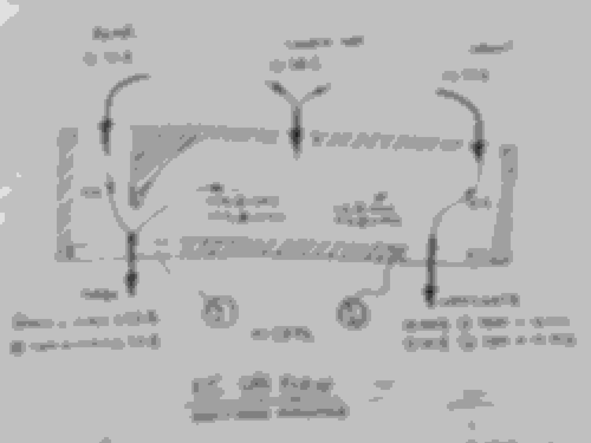
Have had a few doubters lately about how this works so thought it was worth doing a diagram showing what is happening inside the manifold. It's all estimates based on experimentation over the years, plugging numbers into Matchbot to get wastegate % and some best guessing.
The main point I wanted to make was to show how the Siamese port balances the pressures at the end ports by eliminating flow along the length of the manifold. We know that extra pressure can be generated if flow is excessive in any one direction and the diagram shows why that never happens.
The worst case scenario is at spoolup, while wastegate is closed, just before it reaches set boost pressure. In this case there can be over 60% of the gas flowing in the rearmost half of the manifold. However total flow at this point is less than half peak flow and as such emap is very low, so the small additional pressure at the front port is easily tolerated (Remembering that this engine has zero overlap).
It's impossible to know exactly what is happening as the dynamics in play here are extremely complex. There is a distinct possibility that EMAP at the front is actually slightly LOWER than the rear in some situations as flow is biased to the rear and the wastegate has to essentially drag air towards it to flow enough gas and control boost. There is also a strong possibility that the % flows from each port change slightly as it gets harder to get air out of the Siamese port. That's all good given the end ports have virtually a straight shot with minimal restriction.
Once all this is understood it's not so hard to see why this unconventional design works on a Renesis and I make the claim that it flows exceptionally well!
Have to take some blame for the existance of above post, so let me begin my case by saying I'm not looking at dissing or claiming to know better. If anything, I'd love to wake up tomorrow a bit smarter than I did today. Also, I too use lots of assumptions and am by no means a CFD engineer though I did sth. related to this in university. Would love it if someone could model a renesis exhaust in Ansys!
My point was about boost to emap ratio on above setup compared to mine(traditional snake-y tubular manifold vs this log one). I'm getting 2.25 -> 2.5 times the emap, while this setup seems to do drastically better at 1.5 times. My turbo is a gtx3076 gen2 in a 0.86 A/R turbine hsg + a 44mm ext. wgt. The turbine characteristics of the g30-660 seem to match closely enough to mine not to justify the huge reported EMAP readings. As far as garret's site tells me, my turbine should flow 90% as much as the g30-660 one. Compressors are similar, with mine being slightly bigger and 1-2% more efficient up top.
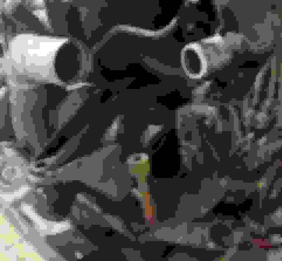
My emap measurement point was this one:
So this got me thinking where could this difference come from...
I assume the little port on the bottom, to the left of the WGT flange is where the measurement is done? Well, here begins my case...
The locomotive of my train of thought is that... the siamese port doesn't flow anything relevant in comparison with the side iron ports. The siamese insert takes up a LOT of the area in the middle so in that 1cm of width left for each rotor... there can't possibly be enough area for a significant % of exhaust gas to pass. My guess would be that out of a total flow of 100%, the side iron ports do 80% and the siamese only 20%. That is guessed on the shape of the siamese insert and available width of the middle iron.
If that theory holds truth, then measuring anywhere in the blue segment marked with a **? is pointless, since there's hardly any flow going on there. The measurement point should be changed to 2 locations, simultaneously, in the purple areas with 5* and a ?. I also understand this is much easier said than done. But it may reveal that rotors don't run the same EMAP.
Other answers that can only be guessed:
*?: does any gas pass from the siamese port towards the wastegate?
***? and *** *?: how do we compute, accurately, which percentage does the wgt/turbo flow ?
*** **?: Given the assumption that the siamese port doesn't flow enough to equalise pressure at both ends of the log, should then EMAP be measured at both ends? Does the casting thickness/design allow for 2 extra taps?
*** ***?: Has anyone measured any backpressure from the rest of their exhaust? Mine still adds 4 psi @ 7500 @ 15 psi @ wot despite not having a catalyst but I do run mufflers and a resonator. For this I've placed a pressure sensor as close to the point where the spent gas from the wastegate and turbo merge again.
The least I could do to help answer some of these is offer one of my obd2 expander kits. With it you can log with mazdaedit up to 5 pressure channels at once, besides whatever the stock ECU can do. 1 channel at the compressor wheel outlet, 1 ch at the intercooler exit port, 1 ch at LIM nipple, 1-2 ch at the log exhaust manifold. For ref. at 330g/s of flow, I'm getting 0.2-0.3psi drop of pressure from compr. wheel to IC outlet, no measurable loss from IC outlet to LIM, and then ~30 psi of EMAP at 7500 rpm.
Given the assumption that the siamese port doesn't flow enough to equalise pressure at both ends of the log
I'll just answer this incorrect assumption and you can see how it might change your thinking.
The Siamese port flows approx. the same (or slightly more) than either of the side ports. I know this to be true .. absolutely no question!
How do I know ?
1/Years ago a video was posted showing an NA Renesis with headers on an engine dyno...... only one of the header tubes glowed red - the Siamese . For that to happen the Siamese would need to flow more than either front or rear.
2/That video gave me confidence to try something unusual. My previous manifold design used the Siamese port exclusively to supply the wastegate (See Brettus turbo 111 thread). Set up like that I was able to run at boost pressures down to about 7-8psi at peak rpm. Plugging into matchbot reveals that the siamese would have to flow more than 40% of the total engine output to achieve that!
As far as why my manifold works so much better :
1/Straight shot into the turbine from the rear port preserves the pulse energy from that port.
2/Lower volume
3/Better heat retention
4/Less bends all round
5/You run a T25 flange (vs T3) which is just too small and restrictive
6/More efficient turbo (compressor similar but turbine flows more and is more efficient ) BTW - looks like a T04b compressor housing in the pics - I found that housing to be quite inefficient on my GT35 setup .... adds 2-3 psi emap on it's own.
7/More efficient intercooler
8/ Exhaust post turbo is more free flowing
9/Possibly more free flowing intake ...is yours 76mm minimum diameter with a large filter ? The intake can make a huge difference if it's in any way restrictive.
All of those are making a small difference with perhaps 1/ being the biggest, but all combined it's a BIG difference.
I suggested years ago that you should start playing around with Matchbot because it will give you a better understanding of how each aspect of a setup affects things .
Constructive disagreements are the best. One of my slogans, "when you're wrong, you really learn something". And when you guys take the time to explain the opinion, we all learn(well most of us..), regardless if its right or wrong.
Curious to know .... last time I saw your logs at 10psi you were seeing 30psi EMAP (3:1 ratio) , how did you get it down to 2.25-2.5 ?
I do my tuning from boost control first to ignition last. I play with my EBC to get 10 psi across the rev range; until I dial that I set an extremely rich AFR and with 8 deg. of timing. Emap was over 30psi. Still, under these conditions an overboost won't kill my engine.
After getting boost well under control at all gears and TPS %, I go back to 11.5-12 AFRs and 18deg. of timing at redline. Emap dropped to 23psi. At 15psi boost, I get 36 psi emap. Sounds bad, but makes a lot more early-mid range torque.
Interesting - That's not something I've seen myself. Anyway those numbers (2.2-2.5) are about what I would have expected after everything you have done to improve the system. I was really surprised when you were showing 3:1 ratio.


 ), regardless if its right or wrong.


