
OEM Nav Hood controls w/o custom PCB.


OEM Nav Hood controls w/o custom PCB.
I figure with me leaving the 8 community in general I would share this for the many people who have asked me how I did it.
This is a crude and simple way to get the controls on the oem navigation hood to work if you're installing it in a non-nav car where the wiring harness doesn't exist.
You will need:
Philips Screwdriver.
Sodering Tool.
Wire, something like 14awg.
OEM Navigation Hood with the stock PCB intact.
Now we won't be working on the PCB inside the hood assembly itself, instead we are working on the smaller one where the wiring harness would plug in. What you will be doing is simply soldering some wires to this smaller PCB to just power the PCB as if the OEM wiring harness were plugged in. This involves soldering 3 wires, one for a ALWAYS ON (even when the key is not in) 12v source, one for SWITCHED 12v (cigarette lighter), and one for ground.

2 Philips Screws hold this little assembly together.


As you wiggle it loose you will have to undo the ribbon cable and the other mini 4 pin connector. Don't pull too hard, examine the ribbon and you'll see you have to move the tabs to get it out.

After you separate it set aside everything else and take apart the little thing. Bunch of screws.. and..

The soldering tool I used.

Now examine this diagram:
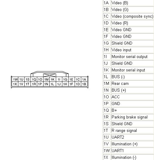
We will be soldering wires to pin's 1O, 1P and 1Q. 1O will be for switched power. 1P will be for ground. 1Q will be for always on 12v.
In relation:

Now you will see that I could not show you were pin 1P is. 1P is directly under 1O in the picture above. Therefore I had to solder the wire on the underside which you will see in a few steps.
Basic soldering now.. yes it's sloppy.

Red wire is Pin 1Q (ALWAYS on power) and Grey wire is Pin 1O (switched power).
Now below, you can see how I had to solder Pin 1P for Ground. Very tight but doable.


Pretty much done..

Folding around the ground wire the metal assembly won't fit.. so had to cut a little notch in the end..

After resassembling everything in reverse order.. the finished product..

That's it! Now you just run a wire from the battery, make sure you put in an inline fuse within 12 inches from the battery, to the red wire (1Q). 1P is straightforward and you can ground it anywhere, I did it in the passenger footwell behind the carpet or you can do it in the shifter area. The grey wire for pin 1O (switched power) you can tap the cigarette lighter harness, MAKE SURE YOU TAP THE RIGHT ONE.. it should only be powered when the key is switched!!
So when everything is wired up the Open and Tilt buttons should function as they do in an OEM install. The nav should also open and close itself if you had it open prior to removing the key, and vice versa.
If you would want to get the buttons to light up you would wire Pin 1V to the CIGARETTE LIGHTER BULB wire and 1X accordingly.
Any questions, feel free to ask!
This is a crude and simple way to get the controls on the oem navigation hood to work if you're installing it in a non-nav car where the wiring harness doesn't exist.
You will need:
Philips Screwdriver.
Sodering Tool.
Wire, something like 14awg.
OEM Navigation Hood with the stock PCB intact.
Now we won't be working on the PCB inside the hood assembly itself, instead we are working on the smaller one where the wiring harness would plug in. What you will be doing is simply soldering some wires to this smaller PCB to just power the PCB as if the OEM wiring harness were plugged in. This involves soldering 3 wires, one for a ALWAYS ON (even when the key is not in) 12v source, one for SWITCHED 12v (cigarette lighter), and one for ground.
2 Philips Screws hold this little assembly together.
As you wiggle it loose you will have to undo the ribbon cable and the other mini 4 pin connector. Don't pull too hard, examine the ribbon and you'll see you have to move the tabs to get it out.
After you separate it set aside everything else and take apart the little thing. Bunch of screws.. and..
The soldering tool I used.
Now examine this diagram:
We will be soldering wires to pin's 1O, 1P and 1Q. 1O will be for switched power. 1P will be for ground. 1Q will be for always on 12v.
In relation:
Now you will see that I could not show you were pin 1P is. 1P is directly under 1O in the picture above. Therefore I had to solder the wire on the underside which you will see in a few steps.
Basic soldering now.. yes it's sloppy.
Red wire is Pin 1Q (ALWAYS on power) and Grey wire is Pin 1O (switched power).
Now below, you can see how I had to solder Pin 1P for Ground. Very tight but doable.
Pretty much done..
Folding around the ground wire the metal assembly won't fit.. so had to cut a little notch in the end..
After resassembling everything in reverse order.. the finished product..
That's it! Now you just run a wire from the battery, make sure you put in an inline fuse within 12 inches from the battery, to the red wire (1Q). 1P is straightforward and you can ground it anywhere, I did it in the passenger footwell behind the carpet or you can do it in the shifter area. The grey wire for pin 1O (switched power) you can tap the cigarette lighter harness, MAKE SURE YOU TAP THE RIGHT ONE.. it should only be powered when the key is switched!!
So when everything is wired up the Open and Tilt buttons should function as they do in an OEM install. The nav should also open and close itself if you had it open prior to removing the key, and vice versa.
If you would want to get the buttons to light up you would wire Pin 1V to the CIGARETTE LIGHTER BULB wire and 1X accordingly.
Any questions, feel free to ask!
Last edited by alz0rz; Apr 7, 2010 at 11:52 PM.
it's pretty easy.
you remove the radio.
there are 2 screws holding the vents in place.. remove those and remove the vents.
then there are only 2 screws holding the nav panel in the front. once you remove those you have to CAREFULLY pull it up.. there are many clips holding it in place.
then you do the undo wiring harness and it's out!


Sleeps with one eye open!
Joined: Oct 2006
Posts: 367
Likes: 0
you mean getting the whole panel out of the dashboard?
it's pretty easy.
you remove the radio.
there are 2 screws holding the vents in place.. remove those and remove the vents.
then there are only 2 screws holding the nav panel in the front. once you remove those you have to CAREFULLY pull it up.. there are many clips holding it in place.
then you do the undo wiring harness and it's out!
Thank you VERY MUCH for your help!

Ha, soldering not your strong point? From what it looks like if you're going to do this (which I am in a few days) you'll need flux, because looks as if that solder does NOT want to stick at all.

Sleeps with one eye open!
Joined: Oct 2006
Posts: 367
Likes: 0
Do you think if I jump the illumination leads to my lilliput power leads I could preserve the stock on off functon or should I julmp the acc and b+ leads? I have everything soldered and reassembled, but I'm second guessing myself. Want the lilliput to power on when the hood is up and off when hood starts down.
What do you think?
What do you think?
That is not how you should go about doing that. You need a contact switch, I believe deanRx8, the guy who did the mac carPC did this. To give a simple explanation:
Two pieces of metal, one is attached to a wire leading to your source of power (ACC line probably), the other is attached to the lilliput power input.
Line up the contacts so when the hood is open at full (or any tilt points as well) the two pieces of metal touch, therefore completing the switch, but when it is down the connection is broken, therefore no power.
That is how this needs to be done, I'm not sure of what you are talking about doing.... but I wouldn't.

Registered
Joined: Dec 2008
Posts: 21
Likes: 0
From: Montgomery, Alabama
this method is soldering onto the backside of the harness plug socket, correct?
So, if i had the other side of the harness leading from the factory nav, I could just splice the wires in and snip all the others for the same result?
So, if i had the other side of the harness leading from the factory nav, I could just splice the wires in and snip all the others for the same result?

Registered User
Joined: Mar 2010
Posts: 46
Likes: 0
bro alz0rz, thanks a million for fixing the pics!!!
You have saved me, this is exactly what I am going to do with my newly purchsed unit, it has troubled me for months since i got it without OEM cables!
By looking at the last pic with the finishing product, I am kinda confused with the soldered green/red/black cables on the bottom and the three cables on the top (read/yellow/black). Sorry for all this as I am not very technical for all these stuffs. My challenge is, I would like to wire these out of OEM PCB and connect DVD player and TV tunner. I understood from your instruction how how to solder the green/red/black wires to link the PCB for the foldable mechanism, but how do you wire the videos and power etc? could you please explain further?
I have also read from other thread mentioning it requires AV switcher or VGA input in order to connect OEM LCD to DVD player...etc what is this VGA input? and if i want reverse cam, do i just solder 1M? anything else?
Appreciate your kind assistance, Thanks alot mate.


What kinda help are you looking for? I just recently wired mine up, maybe I could help?
it's still sitting on my table waiting on me to decide on what to put in it, but it has been tested and is fully functional right now.
it's still sitting on my table waiting on me to decide on what to put in it, but it has been tested and is fully functional right now.