Dual vent gauge pod for Rx8


 05-26-2011, 10:11 AM
#128
I see you're boosted! what turbo set up you have? sorry a little off topic.
Gauge pod looks great!! why are you taking the A-pillar cover off?
You could use a screw driver and just heat it up with a candle or something then just poke a hole with it, all done anyway... I didn't even use a grommet myself, as the hole I cut is only under 15mm.
Gauge pod looks great!! why are you taking the A-pillar cover off?
You could use a screw driver and just heat it up with a candle or something then just poke a hole with it, all done anyway... I didn't even use a grommet myself, as the hole I cut is only under 15mm.
It's been a long time coming but I think I will be able to fire it up today. I've had to replace quite a few items a long with some new custom stuff.
I had the A-pillar off for some other items that I have mounted by my rear view mirror (Radar Detector and Fuel pressure gauge).
Cheers
 05-26-2011, 07:01 PM
#129
Surf Hard, Drive Hard

Join Date: Feb 2007
Location: Indialantic, Florida
Posts: 7,840
Likes: 0
Received 11 Likes
on
9 Posts
I cheesed out and ran the lines a different way, but then again......I was forced to do so or I would've need a slot about 2 1/2 inches long and and inch wide!

Love the line of site eyeball.
 05-26-2011, 07:07 PM
#130
Surf Hard, Drive Hard
Join Date: Feb 2007
Location: Indialantic, Florida
Posts: 7,840
Likes: 0
Received 11 Likes
on
9 Posts
BTW.....to you two latest guys(Kusanagi and wcs), both setups look great!
05-27-2011, 01:45 AM
#131
Registered User

Join Date: Mar 2009
Location: Adelaide, Australia
Posts: 112
Likes: 0
Received 0 Likes
on
0 Posts
Cheers...!
05-27-2011, 07:55 PM
#132
Surf Hard, Drive Hard
Join Date: Feb 2007
Location: Indialantic, Florida
Posts: 7,840
Likes: 0
Received 11 Likes
on
9 Posts
 You have no idea mate!
There are about 24 individual shielded 30awg wires surrounded by another huge shield inside each cable. (Don't ask me how I know!)

The wires are directly connected in the displays and on the other end is a 24 or 25 pin D type connector.
These end uyp run my two iMFD displays! http://www.plxdevices.com/multigauges.html
Click the video on the right side of that page.
I have one that monitors the OBDII port, and the other monitors oil pressure and temp.
Last edited by Mazurfer; 05-27-2011 at 08:01 PM.
05-28-2011, 03:50 AM
#133
Registered User
Join Date: Mar 2009
Location: Adelaide, Australia
Posts: 112
Likes: 0
Received 0 Likes
on
0 Posts
You have no idea mate! There are about 24 individual shielded 30awg wires surrounded by another huge shield inside each cable. (Don't ask me how I know!)
The wires are directly connected in the displays and on the other end is a 24 or 25 pin D type connector.
These end uyp run my two iMFD displays! http://www.plxdevices.com/multigauges.html
Click the video on the right side of that page.
I have one that monitors the OBDII port, and the other monitors oil pressure and temp.

Careful with the OLED display, and don't let them expose to extreme heat, I had an Alpine 7998R head unit with OLED display in my daily driver, it's OLED display died from the summer heat, and it's not even that hot!
05-28-2011, 10:44 AM
#134
Surf Hard, Drive Hard
Join Date: Feb 2007
Location: Indialantic, Florida
Posts: 7,840
Likes: 0
Received 11 Likes
on
9 Posts
Thought it might be like 5 wires(like RS232).
Luckily I am a NASA certified solderer and spent the next day stripping, soldering, and shrink tubing all 24 wires and shields!

Thank God they were color coded! But wow, were they tiny!

If you are familiar with wire wrap wire, that's about how big they were.

There was no freaking way to accomplish this in the car, so I put it back together on the bench and obviously wan't going to cut the 2nd one! PLX said I couldn't do it and make it work, but I did!
Ended up routing the cables a different way after all that fiasco.

You can see the end results up above or in this thread. https://www.rx8club.com/showthread.p...12147#poststop
I've actually hidden the cables a little better than in those pics, but they sill do run over to the A pillar.
Last edited by Mazurfer; 05-28-2011 at 10:57 AM.
 05-28-2011, 11:22 AM
#136
Surf Hard, Drive Hard
Join Date: Feb 2007
Location: Indialantic, Florida
Posts: 7,840
Likes: 0
Received 11 Likes
on
9 Posts
06-19-2011, 07:01 AM
#140
Surf Hard, Drive Hard
Join Date: Feb 2007
Location: Indialantic, Florida
Posts: 7,840
Likes: 0
Received 11 Likes
on
9 Posts
Not sure that anyone has had to take of the "dashboard".
Go back and read some of the above posts and you will see that there are two basic ways people are running the wires.
Either over to the A-pillar, or down through the bottom of the vent itself.
Go back and read some of the above posts and you will see that there are two basic ways people are running the wires.
Either over to the A-pillar, or down through the bottom of the vent itself.
06-20-2011, 12:33 AM
#141
Triangular Bee Hive
iTrader: (3)

Join Date: Feb 2008
Location: Socal, LA
Posts: 779
Likes: 0
Received 0 Likes
on
0 Posts
With everything inside the dashboard I didn't thought I would be able to make it with just a wire fishing through the whole thing...hopefully everything goes smooth..
Mazurfer, could you send me the PDF that you sent to Kusanagi?
After reading the thread, I'm still not sure which and where I could tap (cut) the wires...
The only electric work I've ever done on the car is switching the bulbs and install stereo for my friend's 03 altima....
Mazurfer, could you send me the PDF that you sent to Kusanagi?
After reading the thread, I'm still not sure which and where I could tap (cut) the wires...
The only electric work I've ever done on the car is switching the bulbs and install stereo for my friend's 03 altima....
06-20-2011, 04:20 AM
#142
Registered User
Join Date: Mar 2009
Location: Adelaide, Australia
Posts: 112
Likes: 0
Received 0 Likes
on
0 Posts
Unless you know how to read schematic diagram, otherwise the PDF won't be of much help, I couldn't understand much at all :P
Depending on the type of gauges you have, what you need to tap into, eg. GND, +12v constant, +12v switch, +12v light.
To get the wire through the vent is very easy, please see my drawing below, after making the hole in the vent, if you stick your head under the dash you'll be able to see the hole from under, of course you'll need a torch, took me 30 seconds to get the wires through.
As Mazurfer said you need to go back a few pages and do some reading, then ask here for anything you're not too sure.

where I drill the vent, my car is a RHD btw.

Depending on the type of gauges you have, what you need to tap into, eg. GND, +12v constant, +12v switch, +12v light.
To get the wire through the vent is very easy, please see my drawing below, after making the hole in the vent, if you stick your head under the dash you'll be able to see the hole from under, of course you'll need a torch, took me 30 seconds to get the wires through.
As Mazurfer said you need to go back a few pages and do some reading, then ask here for anything you're not too sure.
where I drill the vent, my car is a RHD btw.
Last edited by Kusanagi; 06-20-2011 at 04:23 AM.
06-20-2011, 06:54 AM
#143
Surf Hard, Drive Hard
Join Date: Feb 2007
Location: Indialantic, Florida
Posts: 7,840
Likes: 0
Received 11 Likes
on
9 Posts
^.......yeah, he's right about the pdf.
If you tell us exactly what gauges you have, then we could help a little more.
We need to know how many wires each gauge has and what they are labeled.
Refer to your gauge info and let us know what you have.
If you tell us exactly what gauges you have, then we could help a little more.
We need to know how many wires each gauge has and what they are labeled.
Refer to your gauge info and let us know what you have.
06-20-2011, 12:03 PM
#144
Triangular Bee Hive
iTrader: (3)
Join Date: Feb 2008
Location: Socal, LA
Posts: 779
Likes: 0
Received 0 Likes
on
0 Posts
Sorry for missing info, my apology.
Here are the gauges I got and list of wires.
Prosport performance oil pressure gauge:
Green- to sender
White-12v acc
Black-Ground
Orange-12v light
Red- 12v acc
Sensor:
Black- "WK" on sender
Green- "G" on sender
Lighting Diagram: White to acc power, amber (orange?) to parking lamp
Since there is no separate set of wires for sensor, I'm not sure how I should wire the Black one...
I'll contact prosport regarding this issue.
-------------------------------------------------------------------
Prospot Premium water temp gauage:
Red-12v Constant power
Black-Ground
White-12v acc
Orange-Headlight switch
Lighting Diagram: White to acc power, amber (orange?) to parking lamp
06-20-2011, 12:28 PM
#145
weeeeeeeeee
iTrader: (12)

Those gauges' connectors will fit through the air vent and down past the steering column without issue if you cut big enough of a hole in the air vent for them... likely no more than 3/4" one.
06-20-2011, 07:14 PM
#147
Registered User
Join Date: Mar 2009
Location: Adelaide, Australia
Posts: 112
Likes: 0
Received 0 Likes
on
0 Posts
Ok... since I have different gauges, I can only point you to what I have in common, others may be able to help with the rest.
(1) GND, you can just find any good chassis point under the dash, I used the 10mm hex bolt right behind the fuse box, I hooked up all the GND from the gauges to one 14gauge black crimped to a fork connector like this
(2) +12V constant, I tapped off the fuse box, get the following fuse tap from your local electrical supplies with matching ampere

and slot into the fuse box slot (11) as shown in pic, which is for audio, make sure the wire end of the tap is on the right hand side of the fuse, so that the gauges are protected by the same fuse too. Note that from 1-6 in the fuse box are +12V ACC, means they are hot only when your key is on ACC, 9-14 slot are +12V constant.

(3) +12V ACC, as above, use the fuse tap with matching ampere, I would use (1) which is used by cigarette igniter, at least when the fuse is blown it won't affect anything important, note that the aircon fuse is hot only when ACC and Fan switch are both turned on, don't use that.
(4) +12V ON, the wire is hot only when your key is at ON position, one click above ACC, which is the one I used, this connection remains HOT when you crank your engine, means DO NOT tap any power hungry device to this wire! but as a sensing switch is OK, see the following link by Robin Yang, read from point (1) to point (9) use the Black/Yellow wire only. The reason I used this wire is due to the gauges I have has opening sequence, if I hook up to ACC, the opening will start, then when I crank the engine, everything with ACC will be temporary shut off to reserve power for the starter motor, this way the gauges will be cut off, once engine started the opening sequence will start again, so this is annoying to see the opening sequence twice when you start your car.
http://www.hi-impact.org/ryang/modif...rbo_timer.html
(5) +12V driving light, most would tap off from the cigarette socket lighting, but I tapped off from steering column harness, where the light stalk is, unfortunately I couldn't tell you which wire as I forgot to take picture, but you could search and follow others who tapped into the cigarette socket light.
Hope this helps.
(1) GND, you can just find any good chassis point under the dash, I used the 10mm hex bolt right behind the fuse box, I hooked up all the GND from the gauges to one 14gauge black crimped to a fork connector like this
(2) +12V constant, I tapped off the fuse box, get the following fuse tap from your local electrical supplies with matching ampere
and slot into the fuse box slot (11) as shown in pic, which is for audio, make sure the wire end of the tap is on the right hand side of the fuse, so that the gauges are protected by the same fuse too. Note that from 1-6 in the fuse box are +12V ACC, means they are hot only when your key is on ACC, 9-14 slot are +12V constant.
(3) +12V ACC, as above, use the fuse tap with matching ampere, I would use (1) which is used by cigarette igniter, at least when the fuse is blown it won't affect anything important, note that the aircon fuse is hot only when ACC and Fan switch are both turned on, don't use that.
(4) +12V ON, the wire is hot only when your key is at ON position, one click above ACC, which is the one I used, this connection remains HOT when you crank your engine, means DO NOT tap any power hungry device to this wire! but as a sensing switch is OK, see the following link by Robin Yang, read from point (1) to point (9) use the Black/Yellow wire only. The reason I used this wire is due to the gauges I have has opening sequence, if I hook up to ACC, the opening will start, then when I crank the engine, everything with ACC will be temporary shut off to reserve power for the starter motor, this way the gauges will be cut off, once engine started the opening sequence will start again, so this is annoying to see the opening sequence twice when you start your car.
http://www.hi-impact.org/ryang/modif...rbo_timer.html
(5) +12V driving light, most would tap off from the cigarette socket lighting, but I tapped off from steering column harness, where the light stalk is, unfortunately I couldn't tell you which wire as I forgot to take picture, but you could search and follow others who tapped into the cigarette socket light.
Hope this helps.
Last edited by Kusanagi; 06-20-2011 at 07:25 PM.
06-21-2011, 12:01 PM
#148
Triangular Bee Hive
iTrader: (3)
Join Date: Feb 2008
Location: Socal, LA
Posts: 779
Likes: 0
Received 0 Likes
on
0 Posts
Awesome! Thanks a million, Kusanagi, this is exactly what I was looking for!
You are da man!
Just an update on my progress, I got the wires through the dashboard, but instead of fishing it upward, i had to pull it downward from the top because the connector head is larger than the hole I drilled. (I taped all the wires together) Hopefully I'll get everything install by weekend.
Cheers~
Last edited by ShinkaEvo; 06-21-2011 at 12:13 PM.
06-21-2011, 07:06 PM
#150
Surf Hard, Drive Hard
Join Date: Feb 2007
Location: Indialantic, Florida
Posts: 7,840
Likes: 0
Received 11 Likes
on
9 Posts
Good Job Mate!
Can't add much to that!
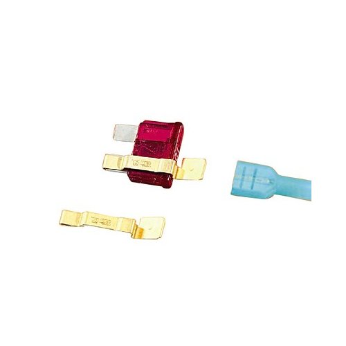
I'm sure you have them in Oz as well(somewhere), but here I chose to just buy these(what I will call Fuse taps) that are a bent and curved piece of metal that fit around one leg of the fuse.
You then put the normal fuse back in the fuse box with the tap around the one leg.
At the other end of that little tap leg is a spade terminal......where of course you can then use a spade terminal(like what you show for your ground).
This way if I pop a fuse, then I can just pull that fuse and replace without having to buy the whole fuse arrangement you have. No big deal though. There are many different ways and things to purchase that will work.
I'll see if I can find a pic online of what I have. Got them at Autozone.........which is a chain in the States, but again, no big deal.
Oh.....and for the most part, when I have multiple grounds............in this case at my boxes and gauges. I tie(solder) them all together there(fairly closely together) and run one larger gauge wire over to the grounding point.....which as you know id the same as yours. At my sensors, I will do the same thing......tie together close to the sensors and run one large @ss ground wire over to grounding point in the engine bay.
I'm helping another member right now that I believe as introduced a rather vicious, and unintentional ground loop in his system/car.
Can't add much to that!
I'm sure you have them in Oz as well(somewhere), but here I chose to just buy these(what I will call Fuse taps) that are a bent and curved piece of metal that fit around one leg of the fuse.
You then put the normal fuse back in the fuse box with the tap around the one leg.
At the other end of that little tap leg is a spade terminal......where of course you can then use a spade terminal(like what you show for your ground).
This way if I pop a fuse, then I can just pull that fuse and replace without having to buy the whole fuse arrangement you have. No big deal though. There are many different ways and things to purchase that will work.
I'll see if I can find a pic online of what I have. Got them at Autozone.........which is a chain in the States, but again, no big deal.
Oh.....and for the most part, when I have multiple grounds............in this case at my boxes and gauges. I tie(solder) them all together there(fairly closely together) and run one larger gauge wire over to the grounding point.....which as you know id the same as yours. At my sensors, I will do the same thing......tie together close to the sensors and run one large @ss ground wire over to grounding point in the engine bay.
I'm helping another member right now that I believe as introduced a rather vicious, and unintentional ground loop in his system/car.
Last edited by Mazurfer; 06-21-2011 at 07:24 PM.
The following users liked this post:
rob babicki (07-28-2021)