

Cobb as a Turbo Tuning Solution and Ideal MAF Placement


Administrator
Joined: Jul 2002
Posts: 21,958
Likes: 115
From: portland oregon
I feel i should get this out there. I did not set up my intake the way i did because of the reasons you posted. My reasons are that i did not want to route the maf to the back of the car and deal with the piping issues of getting a pull through to work with the limited room or signal issues extending the wires. I decided to keep it up front because i had the room to do a long straight run with screens and i could then reuse my AEM set up. It was decided because i already had spent money on parts and i had the room to do it. I also would have not gone this route if i could not us the Access Port. Do I have some advantages if i have mechanical issues Yes, but regardless FI requires matience and check more than just a n/a car. I feel not checking couplers and hoses or monitoring gauges on a FI car is like owning a NA rotary car and never checking the oil.
Last edited by bumblebeerx8; Feb 15, 2011 at 02:52 PM.

It isn't a "bad" idea actually, just redundant.
However, it is a band-aid in more than just a couple of ways, not least of which that you are just masking the tuner's inflexibility.
MAP-based tuning was the status quo for a long time.
So was the horse-drawn carriage.
However, it is a band-aid in more than just a couple of ways, not least of which that you are just masking the tuner's inflexibility.
MAP-based tuning was the status quo for a long time.
So was the horse-drawn carriage.

I like the fact that you have dared to question something that has become the standard "best practice" for RX8 tuning . I like to do this kind of thing myself - always makes for a good argument/discussion.
However , I think you are in a no-win situation here . Cobb(or PT in my case) has proven itself to be reliable and the mechanical issues you speak of have not become apparent . If there was one , it would have raised it's ugly head by now for sure .
On the other hand - use of the early MAP based systems that were tried did uncover many issues .
The results do speak for themselves.
However , I think you are in a no-win situation here . Cobb(or PT in my case) has proven itself to be reliable and the mechanical issues you speak of have not become apparent . If there was one , it would have raised it's ugly head by now for sure .
On the other hand - use of the early MAP based systems that were tried did uncover many issues .
The results do speak for themselves.
Last edited by Brettus; Feb 15, 2011 at 03:07 PM.

so I am searching the forums to find the best place to put the MAF for a turbo setup using the cobbs, I want to make tuning for jeff very easy
this thread is near the top , I see "Cobb as a Turbo Tuning Solution and Ideal MAF Placement "
Wow I though perfect I will get my answer......
Still not sure how to place the MAF, Just no Turbulance is all I need?
this thread is near the top , I see "Cobb as a Turbo Tuning Solution and Ideal MAF Placement "
Wow I though perfect I will get my answer......
Still not sure how to place the MAF, Just no Turbulance is all I need?


I have made a custom MAF Housing that is exactly like stock/AEM, I have inserted the screen right between the filter and the maf


is there any issues with having bends right before or after the MAF?
Is there any issues with size reduction before or after MAF?
is there any issues with having bends right before or after the MAF?
Is there any issues with size reduction before or after MAF?
My setup is similar in concept to what you have there - but no screens . Size reduction or a bend post maf does not seem to be an issue ...
Last edited by Brettus; Feb 24, 2011 at 08:17 PM.
Administrator
Joined: Jul 2002
Posts: 21,958
Likes: 115
From: portland oregon
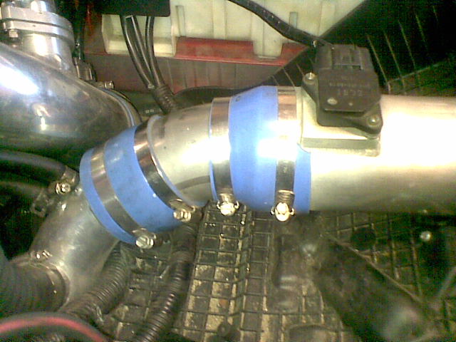
It can cause an issue if the bend or reduction is directly after the maf. we have seen it on setups posted here before. that bend is far enough away and that reduction seems to be as well but you definitely would want either one any closer. A bend where that blue coupler starts would most likely cause issues.

In the real world, 3" is going to be the minimum that will work. Anything less causes untunable errors.
Also, you must have the BOV recirc (if so fitted) mounted far enough away and oriented downstream from the MAF.
There also has to be a good distance between the turbo inlet and the MAF.
You needed to pull 5% at idle and a little more at 65 g/sec (give or take 15), yet the top end (100 g/sec and more) needed to be pushed up by as much as 10% to get the fuel values to align?
That, or you increased your primary scaling value (to shorten injection duration) by up to 10% and decreased it for the sec and P2s by about the same.

Registered User
Joined: Dec 2010
Posts: 4
Likes: 0
Is the MAF on these cars a hot wire type? And if so, wouldn't the blow-through setup's performance degrade over time from oil leaking out of turbo seals? I'm really new to all this, so bare with me if that's a stupid thought... I just kinda skimmed this thread while on break at work.
This is ideal.
In the real world, 3" is going to be the minimum that will work. Anything less causes untunable errors.
Also, you must have the BOV recirc (if so fitted) mounted far enough away and oriented downstream from the MAF.
There also has to be a good distance between the turbo inlet and the MAF.
In the real world, 3" is going to be the minimum that will work. Anything less causes untunable errors.
Also, you must have the BOV recirc (if so fitted) mounted far enough away and oriented downstream from the MAF.
There also has to be a good distance between the turbo inlet and the MAF.
Hmm. Lemme guess:
You needed to pull 5% at idle and a little more at 65 g/sec (give or take 15), yet the top end (100 g/sec and more) needed to be pushed up by as much as 10% to get the fuel values to align?
That, or you increased your primary scaling value (to shorten injection duration) by up to 10% and decreased it for the sec and P2s by about the same.
You needed to pull 5% at idle and a little more at 65 g/sec (give or take 15), yet the top end (100 g/sec and more) needed to be pushed up by as much as 10% to get the fuel values to align?
That, or you increased your primary scaling value (to shorten injection duration) by up to 10% and decreased it for the sec and P2s by about the same.
After taking into account the 3% size diff. from stock and the changes I've made to the Ve table it ends up around -ve 6% at idle to 85g/s then tapering to -ve 4% from approx 150g/s onwards . That gives close to zero fuel trims and pretty good alignment with called for fuel values without any jiggery pokery going on with the scaling.
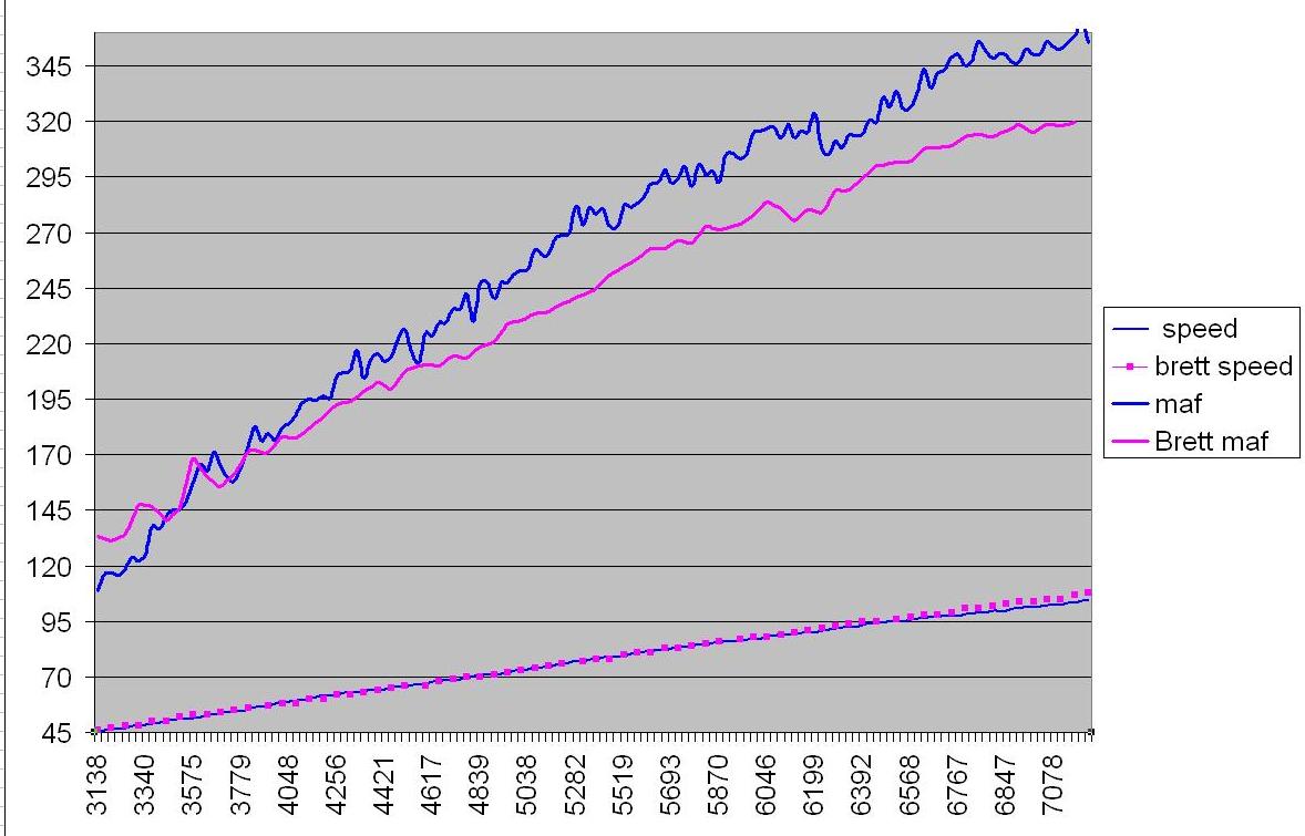
The logs i've posted seem to indicate a much more stable readout than the common AEM setup does .
Last edited by Brettus; Feb 25, 2011 at 03:03 PM.