Header theory:
 11-27-2012, 10:37 AM
#401
Registered

Join Date: Aug 2004
Posts: 664
Likes: 0
Received 0 Likes
on
0 Posts
Since there is no overlap, scavenging hardly occurs and no header design can therefore be very effective. (If there is overlap, very little pressure difference is needed to scavenge the combustion chamber and increase the velocity of the incoming air, which can make headers applied in engines with overlap very effective).
However, one can still try to minimize pressure drop in the entire exhaust system to increase power, which can be accomplished by maximizing the exhaust diameter.
Since pressure drop is approximately proportional to the 1/exhaust_diameter^4 or even 1/exhaust_diameter^5 (unlike for laminar flow:Hagen-Poiseuille , there is no exact analytical equation for turbulent flow): Darcy-Weisbach (Keep also in mind fluid velocity is proportional to 1/exhaust_diameter^2).
Lowering the pressure in the exhaust system would also reduce the viscosity of the air and even further reduce pressure drop: Air - Absolute and Kinematic Viscosity
Of course, there's also an optimum, since a larger pipe will also increase the weight of the exhaust system.
So, has anyone come up with a simple and light header design with just three short stubs leading into one big pipe?
Last edited by globi; 11-27-2012 at 11:47 AM.

 11-27-2012, 11:59 AM
#403
Registered
Join Date: Aug 2004
Posts: 664
Likes: 0
Received 0 Likes
on
0 Posts
Ok, I couldn't find a picture of it.
There was a typo above. It should have said that the pressure_drop is approx. proportional to 1/D^4 or 1/D^5. (So, increasing the pipe diameter has a significant effect on pressure drop).
It would sort of look like this, with the collecting pipe getting bigger after each exhaust stub joining it. http://image.hotrod.com/f/featuredve...model-a-05.jpg
11-27-2012, 03:31 PM
#404
Registered
Join Date: Aug 2004
Posts: 664
Likes: 0
Received 0 Likes
on
0 Posts
Also, if one just assumes that the pressure drop is proportional to 1/diameter^4 (which is a relatively save assumption, since it is probably more: Pressure Drop Online-Calculator), then 2 pipes with the same cross-section as one pipe, double the pressure drop. (Or in other words: Increasing the diameter of a pipe by just 19% reduces the pressure drop by 50%).
So having long pipes leading to a collecting pipe as opposed to short stubs would not only increase weight, but also increase pressure drop.
So having long pipes leading to a collecting pipe as opposed to short stubs would not only increase weight, but also increase pressure drop.
 11-28-2012, 01:53 AM
#406
Registered
Join Date: Aug 2004
Posts: 664
Likes: 0
Received 0 Likes
on
0 Posts
Velocity and momentum is important if you needed to care about any pressure waves in order to improve scavenging. But since there is no overlap there is hardly any scavenging, so you should mainly care about reducing the pressure drop in your entire exhaust system, which can be accomplished by increasing pipe diameter and by reducing sharp turns etc.
Keep also in mind: Increasing velocity increases your pressure drop, pressure drop which you are trying to avoid. Since there is no overlap your exhaust velocity cannot affect intake velocity, so increasing exhaust velocity will primarily increase pressure drop in your exhaust system.
Most effective would probably something like this: http://farm4.staticflickr.com/3034/2...abc5a5ae_z.jpg
and it would also save weight.
11-28-2012, 11:17 AM
#407
^ what globi said. Been trying to get this point across to OD for a while now.
@globi, yeah, it was hard to find. I think I have a download of it in my files that I'll post up when I get a chance. Would be nice if he could commercialize it for a semi-reasonable price.
@globi, yeah, it was hard to find. I think I have a download of it in my files that I'll post up when I get a chance. Would be nice if he could commercialize it for a semi-reasonable price.
11-28-2012, 07:57 PM
#408
In theory you are totally right. I have said before "zoomies" would be the best--but in real life street driving that is not an option. Exhaust systems have to conform to certain restrictions. Within those restrictions is where maintaining velocity becomes important.
Since rotors fire at different times, exhaust leaves them at different times, and pressure waves from gas emerging from one rotor might not be completely vacated through the exhaust system when another comes. This creates back pressure and restriction in the engine's exhaust system and limits the engine's true performance possibilities. Velocity versus capacity is a balancing act within the street designed exhaust system.
Since rotors fire at different times, exhaust leaves them at different times, and pressure waves from gas emerging from one rotor might not be completely vacated through the exhaust system when another comes. This creates back pressure and restriction in the engine's exhaust system and limits the engine's true performance possibilities. Velocity versus capacity is a balancing act within the street designed exhaust system.
11-29-2012, 11:48 AM
#409
Registered
Join Date: Aug 2004
Posts: 664
Likes: 0
Received 0 Likes
on
0 Posts
Exhaust gases will excavate more rapidly (= less pressure drop) with a less restrictive exhaust system (= larger ID, shorter pipes, no sharp bends etc.) and this is the case regardless whether the flow is constant or pulsating (and this is not just theory but fact).
However, a header can be designed (particularly by adapting the length) such that a pressure minimum is reached just before the exhaust valve closes. This pressure minimum scavenges the combustion chamber within a certain rpm range. And this means that a header could actually increase the average pressure drop in the exhaust system, but at the same time still be beneficial and increase power. But if there is no overlap, the combustion chamber cannot be scavenged with any short lasting pressure minimums.
So, having a restrictive header (e.g. elaborate long tubes) in order to provoke certain pressure minimums only increases pressure drop (= power drop) in the exhaust system without being able to benefit from any power increasing scavenging affects (in the case of the RX-8).
(Very little air flows through a plugged straw regardless of what pressure minimums are applied on the other end.)
11-29-2012, 08:28 PM
#410
true we cannot effectively savage the combustion chamber and its true a log manifold can be made to work just as well as a tubed header. The oem log manifold is actually pretty good BUT it can be improved on. Improving on the log manifold is actually more difficult for most people so they get a tubular header. A tubular header does give more cross sectional area than the oem log manifold.
Once you get a header then maintaining appropriate velocity through out the system becomes more important IF you want to maximize the benefits of the header. You dont want to bottleneck the exhaust by going from a total of 5.25 cross sectional inches of exhaust flow to a 2.5 inch pipe. But at the same time you dont want to dump it into a 6 inch deisal exhaust pipe either. there is no room!
I think we both are actually in agreement but are just discussing both sides at the same time?
Dont forget about turbulance
While bends and obstructions in the exhaust system yield lower exhaust velocity, they also result in higher turbulent intensity which exacerbates the losses.
Choosing the correct exhaust pipe diameter is very important when attempting to maximize performance from a custom exhaust system. A pipe too small will result in significant back pressure due to high exhaust velocities (see the Darcy-Weisbach equation ha!).
A pipe too large will result in insufficient flow velocity, causing inertial forces in the pipes to become less dominant over the viscous forces. Also, gas in a larger pipe will cool more rapidly as it goes downstream due to the increased surface area of the pipe (see thermal radiation), causing a decrease in downstream pressure. Relating this to performance (and as stated in the performance community), a smaller exhaust will give great low-end power as it will move the exhaust great at lower engine speeds, but will also net poorer high-end power due to the significant back pressure at higher exhaust velocities. The exhaust gas cannot get out of its own way.
Last edited by olddragger; 11-29-2012 at 08:31 PM.
 12-02-2012, 05:12 AM
#413
Registered
Join Date: Aug 2004
Posts: 664
Likes: 0
Received 0 Likes
on
0 Posts
Just for clarification.
A larger diameter is only effective up to a certain point, since exhaust system weight is also proportional to the exhaust diameter and any sudden pipe diameter changes also increase pressure drop (e.g. a large pipe starting directly at the exhaust port would increase pressure drop due to an increase of turbulent flow). Also, a diameter increase between approx. 15% and 20% already reduces average pressure drop by 50%. So, one already ends up with significant results with only small diameter increases (no need for 'diesel-pipes').
Also, gas temperature is proportional to pressure. So the larger the pipe diameter, the larger the pressure drop and with it the temperature drop. And this immediate pressure related temperature drop is way more significant than any temperature drop related to the contact with the exhaust pipe. In addition, if exhaust velocity is increased (in a smaller tube), exhaust gases have less time for a temperature exchange with the surface area of the exhaust tube (so a smaller tube may actually result in a reduced heat exchange with its surrounding area (=less thermal radiation and higher exhaust gas temperature)).
Of course, a less restrictive exhaust is primarily effective at high loads and high rpms. (There's no significant torque increase at low rpms with a less restrictive exhaust system including header (in the case of the RX-8)).
PS: It's not a surprise that many headers resulted in small power gains over the stock manifold, because they are still less restrictive, even if they use three individual pipes. But these headers would be even less restrictive (and lighter), if they had much shorter individual pipes (e.g. as shown in the V8-flathead example above).
Last edited by globi; 12-02-2012 at 05:15 AM.
12-02-2012, 05:52 PM
#415
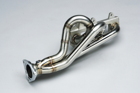
Reposting these pics of TeamRX8's manifold (with permission). Not easy to fabricate, so one reason welding constant-diameter tubes together is more popular. I'm guessing that the taper is done to keep the gas pressure roughly constant as it exits, so all 3 ports see roughly the same backpressure. I'd rather have this than any header for the Renny, but suspect it'd be very expensive to produce.
12-03-2012, 09:16 AM
#416
Registered

Join Date: Oct 2010
Location: North America
Posts: 33
Likes: 0
Received 0 Likes
on
0 Posts
After reading this entire thread over the last 2 nights at work, I've learn quite a lot about headers, I think my Uncle Ray (who's a good welder/ fabricator ) and I are going to try to tackel a project like this this summer. Thank you Olddragger and everyone else you have inspired me to go out side of the box. I posted this online to some of my Rotary Head friends via Facebook this is one of the best reads yet. 
Collective mines make for a very interesting discussion!!
Collective mines make for a very interesting discussion!!

 , yes they do.
12-03-2012, 10:57 AM
, yes they do.
12-03-2012, 10:57 AM
#418
Registered
Join Date: Aug 2004
Posts: 664
Likes: 0
Received 0 Likes
on
0 Posts
Hey nice manifold TeamRX8!
If I were allowed to add any constructive criticism at all, I would argue that pipe 2 and 3 should also have a bent/curve and merge into the collecting pipe at an angle (two high velocity exhaust streams meeting at 90 degrees is not ideal). (But I understand that this would be more difficult to manufacture).
HiFlite, the taper is there because the flow is increasing after each merge, but one would probably not need quite such a large diameter increase (since cross-section area only increases by D^2 but pressure drop is proportional to at least 1/D^4). Pressure Drop: Calculation of pressure drops in pipes
I drew a header where a taper would not be needed (see 3D PDF / the dimensions are estimated). I made the central pipe the collecting pipe, because this port is supposed to get more exhaust flow on average (it�s connected to both rotors) and it would also make the collecting pipe start earlier.
The central pipe is 40% larger in diameter than the 2 others and even with 3 times the flow, it would still have well over 30% less pressure drop per unit length than the 2 smaller ones (which are also much shorter though).
All 3 pipes would only need one simple bend in one plane. (They would just be welded onto the gasket-frame-part such that each pipe is on a slightly different angled plane). The 2 smaller pipes would be welded onto the central collecting pipe.
(I believe this could be relatively easy to manufacture. But then again, although I am a mechanical engineer and deal with �fluidics� occasionally or even on a regular basis, I don�t know much about exhaust pipe manufacturing).
PS: Btw, I'm not sure to how many this header-stuff is really useful. Where I live, if one were caught fiddling with the exhaust system before the catalytic converter, they'd be in deep: http://files.newsnetz.ch/bildlegende...ic_970x641.jpg .
12-03-2012, 01:19 PM
#419
Hey nice manifold TeamRX8!
If I were allowed to add any constructive criticism at all, I would argue that pipe 2 and 3 should also have a bent/curve and merge into the collecting pipe at an angle (two high velocity exhaust streams meeting at 90 degrees is not ideal). (But I understand that this would be more difficult to manufacture).
HiFlite, the taper is there because the flow is increasing after each merge, but one would probably not need quite such a large diameter increase (since cross-section area only increases by D^2 but pressure drop is proportional to at least 1/D^4). I drew a header where a taper would not be needed (see 3D PDF / the dimensions are estimated). I made the central pipe the collecting pipe, because this port is supposed to get more exhaust flow on average (it�s connected to both rotors) and it would also make the collecting pipe start earlier.
The central pipe is 40% larger in diameter than the 2 others and even with 3 times the flow, it would still have well over 30% less pressure drop per unit length than the 2 smaller ones (which are also much shorter though).
All 3 pipes would only need one simple bend in one plane.
12-03-2012, 02:07 PM
#420
ok i reread everything i think Team suggested and I am back.
Hyflite--that was one of my observations also. We are working with certain restraints--street based cars--some needing cats--others dont, room to clear the motor mount---all that stuff.
It was dealing with those limitations in which made my system develop the way it did.
I also did not have access to people with-- lets just say-- a high level of the skills set i needed.
Since my system had to make concessions I had to think of some different things--or at least I thought I did.
My back pressure did drop from 4 psi ( not bad) to 2 psi (VERY good). It is quiet enough for the street and no droning with cruising. I have approx $600 invested.
the header that globi put up is very nice--it reminds me of the one i posted for the flathead v/8 ford engine. I too do not think that design would fit easily? He would have to shorten the primaries?
I think part of Teams header that makes it work so well ( including the megaphone) is the BIG primaries he has on it...? I wonder if those are just 2 inch primaries or a little bigger?
.
12-03-2012, 02:53 PM
#421
Measured with a gauge stuck into an O2 or EGT bung? If so, you're not physically measuring backpressure (though this wouldn't be the first time an automotive norm, if it is one, was incorrect). Backpressure is a force along the tube, not transverse to it. Increase the flow velocity enough and the pressure you measure 90 degrees to the flow will appoach zero (absolute). Look up "pitot tube" on Wicki. That's what you need (without the conversion from pressure to velocity).
12-03-2012, 03:00 PM
#422
Registered
Join Date: Aug 2004
Posts: 664
Likes: 0
Received 0 Likes
on
0 Posts
Originally Posted by HiFlite999
Okay, but I don't think that the header you drew would fit in the car.
Also, all pipes could already start at an angle when they are attached to the gasket-frame (so it would even further move to the engine).
3" diameter before it has to drop down
If this is the problem the center pipe could be straight before it drops down to the cat.
Or is the center pipe simply too fat to begin with (as far as space constraints are concerned)?
EDIT: I think going straight and then drop down isn't necessary, otherwise this wouldn't fit either?
Since you pointed out my cross-sectional pressure angle doesn't work, let's try a more mechanical one.
Last edited by globi; 12-03-2012 at 03:20 PM.
12-03-2012, 03:46 PM
#423
If you start with a 3" pipe at the center port you'd have to bend 90 degrees with a too-small radius to keep the outer side within the 5" boundary.
12-03-2012, 04:56 PM
#424
they don't just meet at 90 deg, and some of your thought process above is a bit off
primaries are 2", cone is 2" x 3", cone is angled down slightly so the middle and end primary come in across the top surface - this enters a bit out of the center flow and provides a circular rotation with the front one providing the push out the end. The rest of header and exhaust is all 3" from the last port onward so 3" elbows were used on the manifold at the appropriate angles to try and straighten flow as much as possible. The ports at the primaries aren't merged at all, just a 2" pipe over the rectangular opening just like the OE manifold. I looked at merging it at the manifold interface, bringing the back two primaries in at a gentler angle, etc., but I was on a tight time frame and in the end my gut feeling is the way I did it was easier and likely would accomplish nearly optimum results regardless. My only goal is to get flow out in a minimum weight package, not tuning resonance etc., so a lot of the merging to maintain velocity, diverging cones, etc. is out the window. If I didn't have to be concerned with emissions I could have used three port plates and saved a few more pounds. Even with the OE manifold plate it still only weighs 7 lbs.
While there was a whole metal fab shop at my disposal I mostly used a bandsaw and a drill press with a hole saw to fabricate it. Jigging it up in the drill press to cut the back two primary holes wasn't that difficult, but it would be just as easy to trace and plasma the primary hole shapes out too. It's all T321 stainless except for the OE manifold plate. Used that because we are required to stay emission legal. The primaries and cones are 18 Ga., all the 3" is 20 Ga. T321 all they way to the back end of the car.
This was built back in early 2006. I used it for 2 years, sold it when I moved back to the Stock class for 2 years, then bought it back and still in use today. If you can do it better than go for it. In the end I doubt you'll make any more power, high or low.
.
Last edited by TeamRX8; 12-03-2012 at 05:09 PM.
12-03-2012, 09:53 PM
#425
http://static.speedwaymotors.com/RS/.../9308474_L.jpg
Looks familiar? What works--works.
I measured my back pressure at the secondary o2 bung. I just hooked up a nipple to it and a vacuum/ boost gauge. I know that the actual backpressure number would be different when measured in a more accurate way.
I did measure both systems in the same way and in the same spot so my little modification seems to have had a positive affect. I dont think i increased velocity enough to have influence the reading that much alone? I do see your point and i guess it is possible.
I did have a resonance/droning problem to start with, but adding a vibrant resonator and using exhaust wrap took care of it.
I most certainly have a power increase. Even in the lower rpms of 3-4K.
Last edited by olddragger; 12-04-2012 at 07:33 AM.