
DIY: AEM Twin-Fire CDI Ignition Install


Registered
Joined: May 2005
Posts: 300
Likes: 3
From: Eastern Ontario
OK, fair enough MM. But for the record, the inverter circuit for each of the coils should look like this. BTW, how do you make an image visible in the message, rather than as an attached image file?

Attach images as JPGs and then insert the resultant link (right click on the "attached file" link) into your post as an image.
Like so:
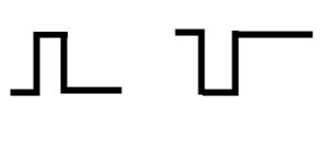
So, why does my circuit work?
While I have you, what would the best way be to make a simple circuit that pulls a 12v input to ground when given a 12v trigger (like a relay)?
Like so:
So, why does my circuit work?
While I have you, what would the best way be to make a simple circuit that pulls a 12v input to ground when given a 12v trigger (like a relay)?
Registered
Joined: May 2005
Posts: 300
Likes: 3
From: Eastern Ontario
MM:
My best guess as to why your circuit works is:
(-1) X (-1) = +1, or in words:
incorrect wiring of incorrect schematic= correct operation
The circuit would work correctly if you reversed the collector and emitter leads (I incorrectly said base and collector in an earlier post).
I'm not quite sure what you mean by 'pulling a 12v input to ground when given a 12v trigger' since both are normally considered inputs. If you wish, I'll try to be of help in any specific applications you have in mind.
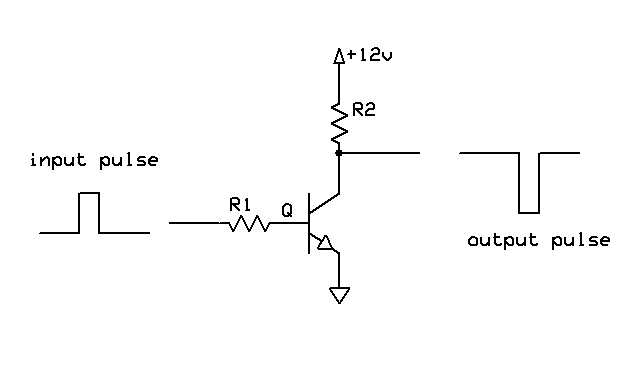
As an example of activating a relay, you could use the inverter circuit where R2 represents the relay resistance. For equal drive and power supply voltages, the value of R1 would be R2(B/F) where B is the transistor Beta (current amplification) and F is some factor to ensure the transistor is driven into saturation (typically 2-5).
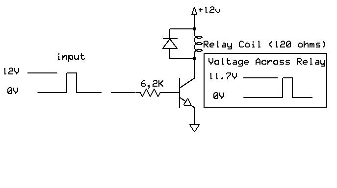
Example: Say your relay resistance is 120 ohms, and the power supply and drive voltages are 12 volts. B is usually at least 100 (see what is probably the world's most common transistor http://en.wikipedia.org/wiki/2N2222). Take F as 2. Then R1 would be 6000 ohms. Use something close and conventional like 6.2K (not too important since there is already a factor of 2 slop in the design and Beta is usually higher than 100).
A point to note if you are using relays is that a high voltage will be developed across the collector of the transistor when the current is interrupted. Unless the transistor is capable of withstanding this voltage, the usual way of eliminating it is to place a reverse biased diode across the relay. This is a common arrangement but it may also be possible to eliminate both the resistor and the diode in a 'follower' type of design.
Still can't post the image directly. When I right click on the link, what option to I select? I don't see anything that allows me to past as an image after selecting something. I use Firefox, but I also tried IE. Why did the image in this post appear as a thumbnail while in the previous post it appeared as a file (the first image was bmp, the second jpg)?
My best guess as to why your circuit works is:
(-1) X (-1) = +1, or in words:
incorrect wiring of incorrect schematic= correct operation
The circuit would work correctly if you reversed the collector and emitter leads (I incorrectly said base and collector in an earlier post).
I'm not quite sure what you mean by 'pulling a 12v input to ground when given a 12v trigger' since both are normally considered inputs. If you wish, I'll try to be of help in any specific applications you have in mind.
As an example of activating a relay, you could use the inverter circuit where R2 represents the relay resistance. For equal drive and power supply voltages, the value of R1 would be R2(B/F) where B is the transistor Beta (current amplification) and F is some factor to ensure the transistor is driven into saturation (typically 2-5).
Example: Say your relay resistance is 120 ohms, and the power supply and drive voltages are 12 volts. B is usually at least 100 (see what is probably the world's most common transistor http://en.wikipedia.org/wiki/2N2222). Take F as 2. Then R1 would be 6000 ohms. Use something close and conventional like 6.2K (not too important since there is already a factor of 2 slop in the design and Beta is usually higher than 100).
A point to note if you are using relays is that a high voltage will be developed across the collector of the transistor when the current is interrupted. Unless the transistor is capable of withstanding this voltage, the usual way of eliminating it is to place a reverse biased diode across the relay. This is a common arrangement but it may also be possible to eliminate both the resistor and the diode in a 'follower' type of design.
Still can't post the image directly. When I right click on the link, what option to I select? I don't see anything that allows me to past as an image after selecting something. I use Firefox, but I also tried IE. Why did the image in this post appear as a thumbnail while in the previous post it appeared as a file (the first image was bmp, the second jpg)?

Just wanted to ask if anyone can post an ignition wiring diagram that identifies each of the three wires that go to each coil's connector. I need to know which one is the signal wire and what the other two represent. Thanks in advance.
Chris
Chris
https://www.rx8club.com/showpost.php...&postcount=157
basically PCM trigger, ground, and power supply
https://www.rx8club.com/showpost.php...&postcount=157
https://www.rx8club.com/showpost.php...&postcount=157
Chris


Registered User
Joined: Mar 2008
Posts: 36
Likes: 0
From: Chicago IL, Poland


holy thread ressurection!
was the light on BEFORE you changed the plugs / wires? Did you alter the coils?
you should find a way to get the code read so you can see what is causing it.
local auto parts stores can pull the code from you. (ie; Autozone)
was the light on BEFORE you changed the plugs / wires? Did you alter the coils?
you should find a way to get the code read so you can see what is causing it.
local auto parts stores can pull the code from you. (ie; Autozone)


Mu ha.. ha...
Joined: Aug 2004
Posts: 14,361
Likes: 3
From: Cali
We all believed it at one point.
Then, I started dissecting coils and experimenting and verified that the white spot is just mineral deposits collected by the magnetic field from the coil.
We also learned that the AEM was **** and the better route was the LS2.
Because I did the legwork.
See how that works?


Jeff did you ever test the coils that mazport used? I know its often a point that the weak point of that system was the ignition box but what about the coils themselves? Just curious.