When you click on links to various merchants on this site and make a purchase, this can result in this site earning a commission. Affiliate programs and affiliations include, but are not limited to, the eBay Partner Network.
Hate to be a bother John, but is it possible to post how your bar is installed? I have the old version of that bar (the tripoint one) and I absolutely can't run full stiff, as it interferes with the shock bodies.
Not sure this picture is helpful or not but it's what I have.
I seem to remember Tamra had an issue where the endlink bolt would hit the shock at some stiffness settings and they either modified it or got a new one sent to them that fixed the problem. I can easily move mine from full soft to full stiff with no interference.
Remember that my bar is spaced forward a couple inches to clear the front pulley on the engine. So the endlinks are at a different angle compared to how they would be on a stock RX-8.
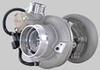
The Mazdaspeed bar works great. The end link looks crazy angled in my picture but that's because the other end of it (control arm side) is disconnected.
Not sure this picture is helpful or not but it's what I have.
I seem to remember Tamra had an issue where the endlink bolt would hit the shock at some stiffness settings and they either modified it or got a new one sent to them that fixed the problem. I can easily move mine from full soft to full stiff with no interference.
Remember that my bar is spaced forward a couple inches to clear the front pulley on the engine. So the endlinks are at a different angle compared to how they would be on a stock RX-8.
Thanks, I had PP send me the new arms to see if i can get more adjustment. You can see the end link almost running into the body here.
Part of the issue is that if you have the arm positioned inward with an angled end-link that under loading the arm tends to deflect sideways (push inward) rather than transmit the full load into torsion on the center bar. The greater the end-link angle, the more arm deflection occurs.
IMO a Z-style machined arm isn�t quite as beefy or rigid as the arms you buy from Speedway Engineering like on the previous RX8 swaybar form Motorsports/Speedsource (pic below). The single bend arm does help clear the shock body as the link is moved forward though.
.
Adding to the clearance issue though is heim type end-links rather than the OE type aftermarket end-links because they have the hex bolt head sticking out on the shock body side. Not sure if these are strong enough and may still stick out too far, but you can try them out
I haven't posted on this in a while. I've been struggling with random misfires and have been systematically tracing everything out to find it. The logs were showing crankshaft sensor errors (meaning the pattern was not what the computer expected). I was really meticulous when doing the wiring so I didn't think that was it. I checked coils, grounds, supplies, everything with no luck. I ended up buying a $65 USB oscilloscope (I really needed one anyway) to scope the cam and crank signals and found the issue. Below is a good crank (yellow) and cam (green) signal out of the sensors, with the engine idling. The crank trigger wheel consists of 16 teeth followed by a two-tooth gap, followed by one tooth, another two tooth gap, 13 teeth, then a two tooth gap. You can see this in the trace. Sixteen pulses, a gap, a pulse, a gap, etc.
That's how it should look. Now here is the same signal with the engine at 5,000 RPM. Obviously, this is completely fucked. The hall effect sensor is mistriggering all over the place. I don't like just replacing parts, but it seemed likely that was the culprit.
And... today was a good day. I got the new crank sensor from Mazdacomp, put that in, and holy crap, my crank triggers look pristine. RPM traces in the logs look a thousand percent smoother. The ECU isn't logging a single crank error in several minutes of revving, so I think this one is licked.
I looked back on my purchases and it looks like the original crank sensor I bought was an aftermarket one. So, lesson learned, buy OEM parts. I did order two sensors in case this one ***** the bed, but I think it was just a case of bad Chineseum parts.
Also, I finished my coil brackets and mounted the Nissan R35 GT-R coils. Probably didn't need them, but it seemed like a good idea. We did see some spark breakup on the dyno which limited us to 405 wheel horsepower at 6,200 RPM. I closed the plug gap which helped, but it still broke up. Now, this might have been an early sign the crank sensor was going bad, but the GT-R coils were something I had and it seems like good insurance. The car should easily make 450 at the wheels and rev to 7,500 RPM all day. I cannot wait to get back behind the wheel. The car was good before, but it's going to be unreal now.
Now that the crank sensor issue is fixed, on to the next problem I've been having. The fuel requirements for this thing exceed the ability of the stock series 2 fuel bowl to stay full. The volume of fuel inside the fuel basket is pretty small because the pump and filter assembly take up probably 80% of the volume. The other problem is E85 requires about 40% more fuel by volume than gasoline to achieve the same lambda. So a good pull at WOT drains the fuel bowl faster than it can refill. I've got a Deatschwerks 340LPH pump in the stock housing feeding a return-style system where the return dumps directly into the fuel basket.
The fuel bowl is filled by two sources - one is the siphon from the passenger's side of the tank, which is not very efficient. But the primary method it's re-filled is by gravity, through a small orifice at the bottom of the basket. I stole a couple pictures from Team RX8 for this.
In the middle of the pic you can see a small piece clipped onto a plastic protrusion on the very bottom of the bowl.
That little flapper is a one-way valve that allows fuel to flow through the aforementioned pipe when the fuel level in the fuel tank is higher than the level inside the fuel pump basket. The idea being that the pressure is equalized when the levels are the same. The problem is that orifice isn't large enough to keep the fuel pump basket fed when the engine is at WOT. When the tank is completely full, overflow through the top of the basket is sufficient to keep it fed (plus the pressure through that orifice is greater), but as the level in the tank drops, that no longer works. It's easy enough to test - at the fuel rail if I disconnect the return hose and run the pump, after a few seconds the fuel flow slows down significantly as the fuel pump basket starts to run dry.
The flapper is much larger in diameter than the opening in that pipe. I didn't measure it, but I'm guessing it's 12 or 13 mm. I decided to try to open up that pipe a bit to improve the flow. The plastic is extremely brittle, so I drilled it out really slowly. An 8.5mm bit followed by a 9mm followed by 3/8", which is about 9.5mm. I didn't try to go larger because the plastic was starting to flex pretty badly. Going from 8mm (50.2 square mm of area) to 3/8" (71.2 square mm) is a 42% increase in area. I also modified the flapper so it can swing open a little farther. I'll test this later, but I'm hoping that's enough to keep the fuel bowl fed even when the tank is at 1/2 or less. I also modified the flapper so it can swing open a little farther.
I just put S2 pump and basket in my car last week. I was thinking of putting the s1 pump on the passenger side and use a manual switch to turn it on and run the feed line to the top of the s2 basket to dump fuel into it. My issues was getting fuel starve during long left turns when fuel tank was anything less than full.
I just put S2 pump and basket in my car last week. I was thinking of putting the s1 pump on the passenger side and use a manual switch to turn it on and run the feed line to the top of the s2 basket to dump fuel into it. My issues was getting fuel starve during long left turns when fuel tank was anything less than full.
That would probably work, but it might be easier to just put another S2 fuel pump assembly into the passenger's side and feed the fuel rail with both fuel pumps.
I'll probably end up installing a surge tank somewhere, or just put a small fuel cell on the passenger's side after removing the stock tank. Mostly I'm just trying to get through this season without having to run 100lbs of extra fuel.
Here's what I did just to give you some ideas. I tossed the whole OEM fuel pump assembly and made my own fuel pump hanger. I needed to make a return-style fuel system and couldn't find a clean way to hack the OEM assembly, so I decided to start with a clean sheet design. It's really simple and was fairly easy to make. It's just a big steel circle with a couple of posts welded to the bottom and some holes at the top. I used a DW300 fuel pump, Radium siphon jet pump attached to the OEM siphon hose, a Radium bulkhead electrical connector, and some ebay bulkhead AN-6 fittings.
It's not pictured, but I used a 3x15 hydramat on the bottom of the pump (attaches directly to the DW300 pump). It sits nicely diagonally in the bottom of the tank. I also routed the return/siphon line so it dumps directly on top of the hydramat, which should help to keep it fed with fuel.
It has worked well, but so far I have only tested it on track down to 1/2 a tank.
Holley's web site says it's to be used with 450LPH pumps, so I'd expect it could support that flow rate. Which is way more than the meager 400hp I'm making on E85.
That is a really slick setup! I may have to copy that. Do you have dimensions? I already have an external fuel filter in my fuel system and I obviously already have a return-style system, so this wouldn't be too much work to implement. I'd need to buy a pump with an 11mm inlet versus the one that I have which uses the stock fuel sock. Plus the hydramat. But I have everything else here to build this, including the radium jet pump.
I should have been more specific. I'd like the dimensions of the bump out in the top plate.
Yes, I could go and measure all of this on my car. But since I'm actively doing events in my car and I don't love breathing raw fuel vapors it sure would be nice to start assembling a second fuel setup that I could swap in and go test without taking my car apart.
Adding a hole to the bottom of the cup didn't work.. I tried that. It works great when the car is stationary but as soon as I'm cornering the fuel sloshes out of the bowl and the car fuel starves.
Given that SportRotary has what appears to be a CAD model of the assembly he made, dimensions should be easy to provide.
maybe cut the hole at the bottom of the basket, remove the pump filter and run a hydramat directly to the pump? if the hydramat can reach both side of the tank, then you wouldn't even need the siphon?
I'll pull up my CAD model tonight and give you dimensions. I might even have a spare lid that I had plasma cut, I'll check for that too.
Thanks!
Originally Posted by trackjunkie
maybe cut the hole at the bottom of the basket, remove the pump filter and run a hydramat directly to the pump? if the hydramat can reach both side of the tank, then you wouldn't even need the siphon?
The 300c pump I'm using (like any drop-in replacement pump) doesn't really have a way to attach the hydramat.
So although Holley claims the 16-111 Hydramat doesn't work with the 65C or 300C pumps, it actually does fit. Seems worth a shot, at the expense of one S2 fuel pump housing, to just slap the hydramat on the bottom of the pump and cut the bottom of the housing out.
not sure if one 3"x15" hydramat would be enough volume to hold fuel for a long left corner. you'd probably need two mat, one on each side of the tank and run the hose together then into the fuel pump. then you can eliminate siphon also. holley website does recommend that setup for saddle tanks.
not sure if one 3"x15" hydramat would be enough volume to hold fuel for a long left corner. you'd probably need two mat, one on each side of the tank and run the hose together then into the fuel pump. then you can eliminate siphon also. holley website does recommend that setup for saddle tanks.
There's no easy way to do this unless you run a Hydramat and pump that use AN fittings. the 3x15 Hydramat is the only one they make that attaches directly to the bottom of a pump with an 11mm inlet.
I could put another powered pump assembly in the passenger's side of the tank, with another hydramat, but that starts to get pretty expensive and at that point I could just put a small cell in the car.
the siphon should still work as long as the pump is getting fuel. if you're going to use the single hydromat, then you should route the siphon return line to dump fuel on top of the mat, and not in the basket. if the siphon keeps feeding the mat, then i think that should work out well.
the siphon should still work as long as the pump is getting fuel. if you're going to use the single hydromat, then you should route the siphon return line to dump fuel on top of the mat, and not in the basket. if the siphon keeps feeding the mat, then i think that should work out well.
The mat is directly below the fuel basket, which will no longer have a bottom
Thanks for the idea of drilling out the trap door hole and modifying the trap door so it can swing out farther. I just took my pump out again to do the mod. You can see the difference between the original 5/16 hole vs the new 3/8" hole with the two different drill bit. Also snip a little off the trap door so it can swing back more. And also removed some material outside the tube so more fuel can get in.