When you click on links to various merchants on this site and make a purchase, this can result in this site earning a commission. Affiliate programs and affiliations include, but are not limited to, the eBay Partner Network.
yep, but that was mostly after an E85 station opened up nearby. It’s been a few years since, but I need to get to it first and see what the deal is.
I was out there this afternoon, making parts runs for other people though. Might have time to start on it tomorrow afternoon. Fortunately there’s a Summit Racing nearby that’s open every day. I’d rather be doing other tasks though.
.
Mine all had to be replaced... they were like swiss cheese when i brought it out of storage and started it up. I couldn't believe how bad they were leaking..
Mine all had to be replaced... they were like swiss cheese when i brought it out of storage and started it up. I couldn't believe how bad they were leaking..
Any idea of the brand of hose you used? This is making me skeptical of what I should be shopping for.
for hard-lines; I was looking at cunifer. Most people use it for brake lines, but I looked into it and it�s fuel compatible as well and even better than stainless steel for corrosion purposes. It can be bent by hand and it�s easy to flare with the basic tools. For long runs it�s likely a bit of a pain to straighten out from being bent in a coil in that it will never be 100% perfectly straight like hard metal lines that are bought by the piece.
Most people would say to use SS braided PTFE for the flexible lines, but this is an interesting video that suggests using nylon braided hose with a compatible rubber lining. It goes into a few details about conductive vs. non-conductive which can result in PTFE hoses having leaks. I wasn�t aware of this point.
However, I used non-metalliic Amarid braided PTFE hose from Speedflow in the engine bay on my NA RX-8 and it was really easy to work with and no stabbing the fingers with SS braiding. Amarid is the generic name for kevlar and unlike nylon has a very high temperature resistance; over 600�F, and also more resistant for abrasion and tearing/cutting than nylon. It�s also very light. SS braided hose is easily 3x heavier, which might be a consideration for certain racing situations. I don�t remember it being so expensive when I bought that 4 years ago though; now -6 is $34/ft and -8 is $45/ft . That�s going to immediately push me to run cunifer hardlines with shorter sections of flex hose at the ends.
That said, I�ve seen people run nylon hose like we have on the flex sections of the factory fuel system for the entire length of the car. I wouldn�t recommend it all. The primary issue being nylon isn�t heat resistant enough and coupled with pressure that�s a major fire waiting to happen.
after reading up more on ethanol causing fuel lines to leak I�ll probably need to pull and inspect the fuel injectors as there�s a chance the lining is breaking loose and potentially clogging them. Possibly might move or install another fuel filter in the system up at the engine bay. The existing one is at the rear by the pumps. Which was maybe a mistake having the long length of flex hose after it going to the engine bay. The moral of the story is to avoid this scenario; do your proper research, then plan and execute accordingly.
.
not sure why the simplest things have to be so difficult 🤦♂️
another “challenge” that needs to be addressed is the HKS BOV is positioned between the turbo and the intercooler rather than after the intercooler - before the throttle body. Figured I’d just weld a new flange on at the elbow into the TB and relocate it, then put a blanking cap in the other flange, but I’ve pretty much searched over all of God’s creation looking for the dang blanking cap/plate and can’t find one. Seems hard to believe nobody makes a blanking cap/plate for something as popular as the HKS BOV. Turbosmart and other manufacturers have them for their BOVs but not HKS as far as I can tell. It only needs to be the correct diameter and thickness as the BOV flange.
edit: forgot to mention there’s a generic 50mm BOV flange blocking cap FS on chinabay, but not clear if it works on the HKS flange or not.
.
not sure why the simplest things have to be so difficult 🤦♂️
another �challenge� that needs to be addressed is the HKS BOV is positioned between the turbo and the intercooler rather than after the intercooler - before the throttle body. Figured I�d just weld a new flange on at the elbow into the TB and relocate it, then put a blanking cap in the other flange, but I�ve pretty much searched over all of God�s creation looking for the dang blanking cap/plate and can�t find one. Seems hard to believe nobody makes a blanking cap/plate for something as popular as the HKS BOV. Turbosmart and other manufacturers have them for their BOVs but not HKS as far as I can tell. It only needs to be the correct diameter and thickness as the BOV flange.
edit: forgot to mention there�s a generic 50mm BOV flange blocking cap FS on chinabay, but not clear if it works on the HKS flange or not.
.
is the hks flange tall enough to get a saw-zaw blade behind? Then just weld a cap on?
I can weld it shut whether cut off or not, or just replace that tube section to the IC etc., but a flat plate (which I already figured out needs to be 50-51mm diameter) of the proper thickness would just just replace and block it off with the same circlip and O-ring seal that performs the same function with the BOV in place. A flat round plate is the simple no-mod-required solution that apparently doesn’t exist.
but haven’t made any progress at all between weather issues, assisting other people, friend from out of town visiting this week, etc., in the meantime I may need another storage unit for the mountain of parts that are accumulating, it’s frustrating …
.
that proved to be much ado over nothing; the BOV flange is mounted on a separate piece of tube between two silicone couplers; easier to just replace the tube rather than mess with a cap for the flange. That�s the price of not being familiar with all the details of somebody else�s work.
but it�s all getting ready to change any way and it becomes a non-issue. Treadstone has a super high efficiency intercooler core on their website and it was 20% off over the holidays. Being only $250 it made sense. I didn�t feel like the Mishimoto one on there now is very good. Plus it�s 12� tall with straight connections at the bottom. With silicone elbows on the inlet & outlet, the front bumper cover openings to the radiator are blocked off entirely. All that�s going to change now though.
no undertray, no side fences between the radiator/oil cooler areas, pretty much all of the bumper openings to the radiator are blocked �
However, the tradeoff is weight; 13.6 lbs for the bare-core according to my bathroom scale
Also been putzing around with fitting the Garrett G30-770 turbo onto the existing turbo manifold. It�s proving to be a bit difficult due to how compact the turbo is and all the prior manifold fabrication not taking any of that into account. It also requires water cooling that the prior turbos didn�t have. Piping the oil drain is the biggest challenge, but it�s going to just barely make it.
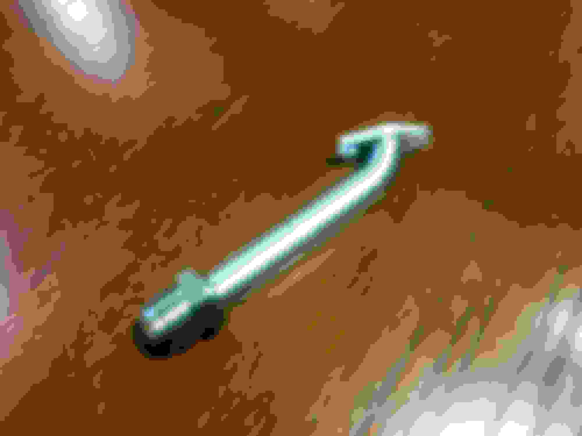
Maybe a bit worse than this situation; except going to make mine from stainless steel with a male hex 10AN fitting rather than steel with NPT coupler:
. . .
Wish I had that much clearance to reach the turbo flange fasteners have to pull the core off to bolt the turbine down and then try to hook up the almost impossible v-band clamp to the CHRA. The v-band clamp only mounts to the turbine in *exactly* one spot.
It all ties in together though because I had already bought a Koyo S2 radiator over a year ago and am now going to switch the cooling system to an EWP setup. Not making the conversion to a V or Z mount yet, but am going to rework the whole thing by moving the IC back towards the radiator to duct in more surface area flow to it and then also duct in and increase more flow to the radiator as well.
Which it has no ducting at all since I bought the car, not even an undertray. I don�t want to criticize Stroker over it though. It was fine for his once in a while drag strip use, but it�s time to get things working a bit more cohesively and efficiently. To wit, I still have the ethanol-rotted fuel lines to straighten out and am also going to rework the rear 2/3 of the exhaust system as well to be a full 3.5� light gauge stainless all the way out. Leaving the front 1/3 for when the eventually new engine and low mount turbo system goes in.
so not posting often, but slowly twiddling away behind the scenes.
.
waiting on some parts to arrive for the turbo oil drain, looks like a 12AN sizing is just going to squeeze in there, but I need the parts in hand to confirm. The front cover fitting is still only a 10AN, but ~2.5 feet of -12 hose will provide more than enough capacity for any temporary backup due to g-loading etc. When the time comes, the fitting will be a -12 as well.
still waffling on the intercooler end tanks, in discussion now with ATP Turbo on modding some existing castings, but am waiting to hear back from them on some input. Leaning towards moving the IC back by mounting it directly to the radiator face with a rubber seal between them to minimize heat transfer from the radiator and also control flow.
The advantages are that the air flow from the front bumper openings can be controlled directly straight thru both rather than it coming in and passing through the IC and then sort of finding it’s way through the radiator. Also the radiator fans are then pulling air through the IC as well when the car isn’t moving.
Getting back to the rotted fuel line issue; there’s a lot of inane crap on the interweb for sizing fuel lines. Most of them reference engine hp, which is an unprincipled approach and then not directly applicable for the rotary output difference compared to a piston engine. Finally found this calculator which references flow, fuel type, line ID, vertical head distance, etc. First however is a discussion page, then the calculator page link:
edit: the key point being you have to put the correct values in it otherwise garbage in - garbage out as noted in the following posts by the people who didn’t follow my lead blindly, but ran their own numbers and recognized my error.
.
waiting on some parts to arrive for the turbo oil drain, looks like a 12AN sizing is just going to squeeze in there, but I need the parts in hand to confirm. The front cover fitting is still only a 10AN, but ~2.5 feet of -12 hose will provide more than enough capacity for any temporary backup due to g-loading etc. When the time comes, the fitting will be a -12 as well.
still waffling on the intercooler end tanks, in discussion now with ATP Turbo on modding some existing castings, but am waiting to hear back from them on some input. Leaning towards moving the IC back by mounting it directly to the radiator face with a rubber seal between them to minimize heat transfer from the radiator and also control flow.
The advantages are that the air flow from the front bumper openings can be controlled directly straight thru both rather than it coming in and passing through the IC and then sort of finding it’s way through the radiator. Also the radiator fans are then pulling air through the IC as well when the car isn’t moving.
Getting back to the rotted fuel line issue; there’s a lot of inane crap on the interweb for sizing fuel lines. Most of them reference engine hp, which is an unprincipled approach and then not directly applicable for the rotary output difference compared to a piston engine. Finally found this calculator which references flow, fuel type, line ID, vertical head distance, etc. First however is a discussion page, then the calculator page link:
used my projected total injector capacity of 9300 cc/min as the E85 flow rate (over 600 rotary whp) since it will provide a worst case value that will never be exceeded. So a 3/8” OD (6AN) x 0.028” wall x 12 feet long cunifer hard line only has a 1.5 psi pressure drop and 1.5 FPS velocity which is plenty fine. All those junk calculators suggest 1/2” (8AN), which adds quite a bit more cost.
There are some hoses on each end that will add some to the dP value, but 6AN hose and fittings have a larger ID than the hardline and it will still be fine for my application.
.
Team, just stumbled onto you findings here and, it sounds almost too good to be true. Not trying to nit-pick at your math but I am not seeing how that is possible. Quickly plugging in your values to this theoretical calculator does not yield the same results you are seeing. I can't even get velocity below 4fps with 1/2" ID. Mind showing me your values? I'll never claim to be perfect, so I could have something wrong here.
Total velocity: 8.87FPS
Total Pressure Loss: 16.1PSI
As well I'll only have 7300cc of injector power (pretty much 700 lb/hr) and I will still need a 5/8 tube (ID of 0.555) to be within a reasonable range according to this calculator, which is what I assumed going into this (on E85). Dunno, just food for thought.
Also jumping on the Aramid AN hoses rabbit hole, have you ever heard of Pegasus Auto Racing? They seem to have the best-priced Aramid AN hoses I can find. I'd much prefer to do all my lines in the engine bay with this stuff purely for the temperature protection, and not be a SS braid.
So I've been messing around with the calculator as well. My question is for the Fuel Lb/hr value is that per injector or the total of all the injectors, I have 6. When I plug my values into the system for gasoline (450 lb/hr), I get a 0.638 psi drop and for E85 I get a 2.69 psi pressure drop.
Oh I bought new redhorse performance 235 series black nylon braided hose second hand for a good deal off a buddy who quit on his REW swap and the max temp rating is 302 degress F! Should I be worried? Need to make sure my hood is well ventilated and I have some serious heat shielding.
Last edited by Warrior777; Jan 25, 2023 at 10:28 AM.
So I've been messing around with the calculator as well. My question is for the Fuel Lb/hr value is that per injector or the total of all the injectors, I have 6. When I plug my values into the system for gasoline (450 lb/hr), I get a 0.638 psi drop and for E85 I get a 2.69 psi pressure drop.
Oh I bought new redhorse performance 235 series black nylon braided hose second hand for a good deal off a buddy who quit on his REW swap and the max temp rating is 302 degress F! Should I be worried? Need to make sure my hood is well ventilated and I have some serious heat shielding.
I'm typically seeing surface temps under the hood of about 50-75C, maybe gets slightly over 80C if real hot (I'd say the most typical temp I see is 65C). I'm talking measuring surface temps of my fuel rails even. That's only ~175F max, so as long as you don't plan on running fuel lines on top of your unshielded turbine or downpipe you should be fine. Measuring my turbine to downpipe flange with an IR gun I see 300-400C (~750F) surface temps and when I went to a 7's day meet (since I wasn't monitoring EGT's) I started shooting everyone's turbine/downpipe that I could as they rolled into the meet with nearly identical results.
Last edited by RotaryMachineRx; Jan 25, 2023 at 10:57 AM.
So I've been messing around with the calculator as well. My question is for the Fuel Lb/hr value is that per injector or the total of all the injectors, I have 6. When I plug my values into the system for gasoline (450 lb/hr), I get a 0.638 psi drop and for E85 I get a 2.69 psi pressure drop.
Oh I bought new redhorse performance 235 series black nylon braided hose second hand for a good deal off a buddy who quit on his REW swap and the max temp rating is 302 degress F! Should I be worried? Need to make sure my hood is well ventilated and I have some serious heat shielding.
For the lb/hr it should be total. (my 2x 1050xds and 2x 2600xds is roughly 700 lb/hr) The calculation should account for maximum usage of the fuel system. So if you decided to max out your injectors to push a gazillion horsepower, the fuel line can adequately feed the rails. Classic scenario of "blowing air through a straw, vs a garden hose".
As to the fuel lines, I don't know if its a problem or not. Knowing you'll being actually racing your car and constantly creating heat in the engine bay, I'd possibly find another use for it. I am probably being too peculiar about my line selection since my car will likely never make it onto a track. One thing to note though, is Pegasus does have the same PTFE SS braided hose (811) that is rated for 500F and has a very small bend radius (1.77"), much better than the Earls stuff (3.28"). Actually probably what I'll end up using as its a great value compared to anything else @ $25 a foot for 10AN I have found so far. Keeping the lines tidy and bent correctly going to the fuel rails from the drivers side of the engine bay is known to be a challenge to keep it tidy.
Thanks for the info.
Yea I will stick with what I got and focus on ducting and heat shielding. Fingers crossed my car does not go up in flames or blow me to kingdom come.
Oh and hopefully my oem fuel supply line repurposed to be the return line connected to the fuel rail with 6an line is not too lacking. Only time will tell. The fuel regulator should help with controlling the pressures of the return line to allow the drop that is needed to prevent the foaming of the fuel correct?
Last edited by Warrior777; Jan 25, 2023 at 01:35 PM.
Oh and hopefully my oem fuel supply line repurposed to be the return line connected to the fuel rail with 6an line is not too lacking. Only time will tell. The fuel regulator should help with controlling the pressures of the return line to allow the drop that is needed to prevent the foaming of the fuel correct?
For the most part I expect a 6AN return line to be adequate for most REW swaps. I wouldn't worry there.
realized later I had a bad number in there and had overlooked it; not surprised that somebody caught and called me out on it, just have been busy and not on the forum for the last several days to update it.
With the 3/8” cunifer ID being smaller than -6 hose ID, the 15 ft length I was using hits the 4 ft/sec velocity limit at ~400 lb/hr on E85, not even close
glad you doubled-checked me 🫡 because I do make dumb mistakes doing it wrong.
the hose I was using from Aeroflow on my NA car to the fuel rail is Kevlar with PTFE liner. I thought Amarid is just the generic name for Kevlar (like PTFE is for Teflon). The difference on Nylon braided is that it will cut/shear easy. A bit of a hazard issue and something to consider …
I got the pieces fabbed up for the stainless steel -12 turbo drain last night; just squeaked it through, but won’’t find out how easy it will be to get the v-band clamp on (if at all) between the turbine and CHRA until after it’s welded up and installed. Had to slot the mounting hole on the bend side because no way to get the bolt in/out otherwise. Made it long enough to position the hose end for easy access and will slide a high temp hose cover over it.
.
kind of suspecting this may be why the T4 housing might have been cancelled on the G25 turbo. It was likely too compact to make it workable.
.
For the most part I expect a 6AN return line to be adequate for most REW swaps. I wouldn't worry there.
it needs more consideration than that because it’s going to depend on the main supply pump(s) setup and the difference between total flow vs bypass flow at any given moment. Which is going to be 30%+ higher if using E85. Otherwise you likely need to employ some strategies as your hp potential grows. Consider if you have a single pump for 500 whp on E85 and nothing else to control the flow (on/off setup), but are idling … that would require a -8 return as well. Even if you have multiple pumps then one or more would need to be staged by a Hobbs switch, or require a pulse-width control setup to manage output vs load requirement, etc. .
the whole point is not to assume anything (consider my own mistake that you pointed out), but rather understand your system and plan accordingly.
The resulting higher return line pressure question was actually addressed in the one fuel line sizing link:
The bypass outlet pressure is ideally ambient atmospheric although return line sizing, if too small, will increase outlet pressure and added rising fuel-pressure line/rail pressures. Another problem with fuel bypasses is the under sizing of the bypass orifice resulting in low flow causing low fuel consumption and erratic fuel rail pressures. A larger bypass would be required or a series of bypasses to bypass the total fuel not used at low fuel consumption conditions.
it needs more consideration than that because it�s going to depend on the main supply pump(s) setup and the difference between total flow vs bypass flow at any given moment. Which is going to be 30%+ higher if using E85. Otherwise you likely need to employ some strategies as your hp potential grows. Consider if you have a single pump for 500 whp on E85 and nothing else to control the flow (on/off setup), but are idling � that would require a -8 return as well. Even if you have multiple pumps then one or more would need to be staged by a Hobbs switch, or require a pulse-width control setup to manage output vs load requirement, etc. .
the whole point is not to assume anything (consider my own mistake that you pointed out), but rather understand your system and plan accordingly.
The resulting higher return line pressure question was actually addressed in the one fuel line sizing link:
.
Team what affect does the fuel pressure regulator have on all this?
Also I finally cut that pipe (bought a harbor freight metal band saw) and will be messaging you with shipment details soon.
Just as it said in that linked webpage; it’s not really a regulator; it’s a bypass. Any pressure on the bypass circuit is going to impact the fuel rail pressure, and it being oversized is preferred over being undersized for that and the other reasons stated there.
Struggling on what to do for the main fuel line, the 5/8” size requirement really throws a wrench into it. Hate to admit it, but a -10 stainless braided line makes the most sense. Still undecided though.
.
Just as it said in that linked webpage; it�s not really a regulator; it�s a bypass. Any pressure on the bypass circuit is going to impact the fuel rail pressure, and it being oversized is preferred over being undersized for that and the other reasons stated there.
Struggling on what to do for the main fuel line, the 5/8� size requirement really throws a wrench into it. Hate to admit it, but a -10 stainless braided line makes the most sense. Still undecided though.
.
Oh I missed that that. It's a bypass. Okay got it. Thanks.
Just as it said in that linked webpage; it�s not really a regulator; it�s a bypass. Any pressure on the bypass circuit is going to impact the fuel rail pressure, and it being oversized is preferred over being undersized for that and the other reasons stated there.
Struggling on what to do for the main fuel line, the 5/8� size requirement really throws a wrench into it. Hate to admit it, but a -10 stainless braided line makes the most sense. Still undecided though.
.
Any opposition to use aluminum? Would be much easier to work with I'd assume? I'm not sure how E85 reacts to aluminum.
would have liked to considered it, but it’s a known corrosive combination and potentially down the road a leak and possible fire is not an acceptable risk given where I am now with the failing not-ethanol-rated hoses.
which I’m pretty sure it has a -8 supply hose now and it’s been working at ~550whp on E50. Even though the new turbo will max out at 525 whp and my goal is mid-upper 4XX, straight E85 adds to the flow requirement. I recognize now that covering gross injector flow isn’t reasonable, but covering max turbo compressor potential for sufficient fuel delivery in the event of an overboost etc. is a sufficient enough safeguard per Howard Colemans recommendation.
so double-check me on this 🧐
525 whp on E85; 70 lbs/min *rotary engine* compressor flow. A 10:1 AFR on gasoline is 6.64:1 on true E85 (0.68 Lambda); 70/6.64 = 10.6 lb/min fuel req’d= 636 lb/hr engine fuel consumption.
the fuel line calculator indicates that 0.444” ID x 1/2” OD x 12 foot long cunifer pipe hits the 4 ft/sec velocity limit with E-85 at ~770 lb/hr. So in theory a 1/2” cunifer pipe is looking sufficient, though right at the limit for worst case whp scenario with bypass and overage flow included. I generally won’t be running near that limit though and should be fine.
mostly being that I failed to consider that the injector sizing includes the 85% capacity limit and also 12% lag. Which oversizes the injectors to account for those factors, but isn’t a representation for the fuel system flow requirement.
.
.


 . That�s going to immediately push me to run cunifer hardlines with shorter sections of flex hose at the ends.


 have to pull the core off to bolt the turbine down and then try to hook up the almost impossible v-band clamp to the CHRA. The v-band clamp only mounts to the turbine in *exactly* one spot.