When you click on links to various merchants on this site and make a purchase, this can result in this site earning a commission. Affiliate programs and affiliations include, but are not limited to, the eBay Partner Network.
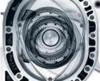
and even more obvious; the L1 plug electrode is seriously burnt back/melted off. Hard to believe it was firing, but the coloration etc. indicates that it was. A testament to how good the IGN-1A coils are.
1/8”+ spark gap, lol 😂 .
comparison photo; the other three were fine except it appears they all have too much spark gap.
.
I don’t agree with this kind of cutting-cost approach at all. It doesn’t pay to not spend the appropriate amount of funds for critical components imo. The car runs and idles smoother now, cold or hot.
I’ve also concluding that there may be an issue with either the AI system or the FMIC. The AI system does work; hold down the manual button on the controller and the IAT will drop right down. What I saw on the dyno though is that IAT is excessively high in general and then keeps increasing throughout the run when the AI system should be on and increasing to max flow.
The FMIC is fully in front of the radiator, which even under full load in the current Texas heat wave is keeping coolant well below 200�F. Still seeing the same IAT situation again just like on the dyno, the IAT is higher than would be expected. Sucking in heated engine bay air isn’t helping any.
Despite this, still not seeing any knock at all on E50 for 15 - 20 psig boost. Or previously on the S369SX-E 1.0A/R at 30 psig with the same approx. IAT. It could well be that the engine being BP’d along with less than ideal rotor sealing and also now being back-pressured with a smaller turbo, is just recycling too much exhaust gas back around into the intake charge. It was easy to swap this turbo on, but I always knew it was a less than ideal combination.
.
so one of my own you-big-dummy foibles; just had to go and be different by switching from my tried and true air filter choice that has always served me well without exception; K&N, and order an AEM Dry-Flow filter instead. Which btw they are by all appearances now made by K&N Filter company as best I can tell. The confirmations I received stated K&N Filter despite ordering it on the AEM Filter site.
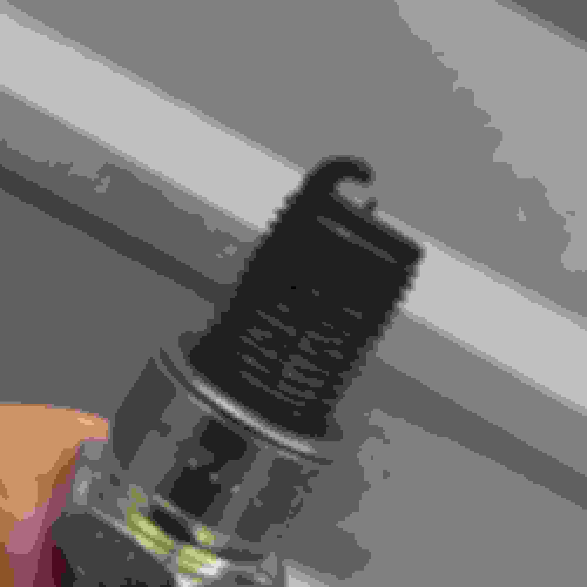
Except nowhere near the same. This filter has maybe 30 minutes only on it; mostly idling, and is mounted directly to the turbo compressor inlet fitting. Which we all know can get pretty hot, but apparently the filter inlet flange material is quite a bit different. Must be some kind of plastic/rubber material rather than silicone based.
Because it’s getting hot enough to melt under the heat of the turbo and the pressure of the clamp to melt-flow out from the flange. When I went to take it off the hose clamp seemed loose, but I know for sure it was tightened. Then I had some trouble pulling the filter off the compressor inlet, which it was obvious why once it popped loose:
So I sent AEM a note and the picture explaining this and expressing my dissatisfaction. No reply yet. So not sure if that’s a $100 bill down the drain (filter and sock) or whether they’ll concede anything on it. Comparing to several K&N filters the material is quite different.
So in summary; AEM filter direct mounted to turbo inlet = Fail! Yeah, don’t do that.
.
I found someone who can fabricate an adapter that will allow connecting the BW marmon flange on the down pipe to the Garrett G30-770 v-band turbine outlet. This is just temporary for testing only with two v-band clamps side x side. I already determined that the exhaust system has enough flexibility to accommodate the extra length it will add to the turbine/DP connection. So I’ll also be able to test the G30-770 turbo too in the present manifold/setup without much difficulty for comparison purposes later when this is all converted to a low-mount configuration etc.
.
It's easy to machine the housing to take a v-band on the BW... much simpler than the Marmon they come with
I agree in principle, except in this particular situation the marmon connections already existed and then I have to modify an existing DP that won’t exist later. That path has hardships which are much more difficult for me to address now. I’ll deal with all of it at the same time later when the situation necessitates having to do so regardless. I perceive this to be the easier path that lets me try a few things before moving on to where it’s eventually all leading to. Again it’s just temporary to allow some testing in the current configuration.
I didn’t get into it before, but I can’t just take the DP loose and then hook it up. I have to disconnect the downstream exhaust from it, then connect the DP to the turbine, then take a 1” ratchet strap and pull the rest of the exhaust forward to mate with the DP. Because there’s about an inch or so of length missing on the DP imo and making it a bit too short otherwise. That’s why I know the marmon adapter is just going to fit in easily. Which is perfectly fine for some short term testing. All that changes later, God willing.
.
I found someone who can fabricate an adapter that will allow connecting the BW marmon flange on the down pipe to the Garrett G30-770 v-band turbine outlet. This is just temporary for testing only with two v-band clamps side x side. I already determined that the exhaust system has enough flexibility to accommodate the extra length it will add to the turbine/DP connection. So I’ll also be able to test the G30-770 turbo too in the present manifold/setup without much difficulty for comparison purposes later when this is all converted to a low-mount configuration etc.
.
Not much to report, but nobody else is updating their threads so maybe I�m not the only one who is experiencing a recent trend of nothing seeming to go either right or easy lately.
I did end up pulling the turbo off to check a few things and then while it was off, reworked the CHRA oil supply line slightly by adding an AN fitting near the CHRA inlet. This now allows swapping the pressure regulator assembly between different turbos easily. Finally got back to reinstalling the turbo again, only to discover the battery was fully discharged down to only 3 Volts. Which then required having to pull the battery and bring it home for charging. Installed a disconnect on the ground post, then left to go home for the night and forgot to disconnect it. Just one thing after another these days, but hoping to be back on track again soon.
The engine is firing up much quicker and running smoother it seems. So the spark plug change definitely helped. Fixing the oil pressure sensor fitting eliminated most of the messy leaks and drips as well. I also removed the AC compressor from the engine since it was just dead weight without having any refrigerant lines, condensor. etc. installed to support it. Baby steps of improvements, but improvements just the same.
.
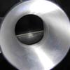
So I had a problem with this disconnect. If you look closely at the picture above (edit: underside pic below shows it better), there’s a white plastic liner between the the disconnect surfaces. They even have the metal material swaged to hold it in place. So it seemed that it was intended to remain in there. I thought that was kind of odd, because then the only actual ground travel path connection is the threaded metal post and the nut insert in the green plastic ****. Sure enough the power steering quit working.
Initially thought I was bitten by the inevitable EPS rack or controller failure. Then thought about it some more and remembered the plastic liner on the disconnect. Since the steering going out happened right after the disconnect was added, I thought maybe not enough battery power was getting through the circuit. It took some effort to dig the plastic piece out. They definitely intended it to stay in place, but after removing it and getting everything back together; EPS problem solved.
So just FYI; an insufficient battery ground resulted in it cranking etc. fine, but not well enough for the EPS to function. Which is quite the upper arm workout. 💪
.
Even on this alternate version, you can see the (black) plastic washer or liner inserted into the disconnect path. That’s Wuhooflu engineering for ya’
yes, I have something similar on my NA RX8. Just have more important fish to fry (and dollars to spend) on this one and so took the cheap way out to get me by.
That one on my NA RX8 is a 200 Amp circuit breaker though with a similar reset/disengage feature. Because the lithium racing battery in it has a built-in auto-disconnect circuit feature for low voltage cut-off with a wired-in push-button ON feature for re-engaging it from the driver seat. I can just bypass all that by disengaging the breaker though more or less the same way, but then have to manually re-engage it back in the trunk area where the battery is located.
It works for now, along with a 45 lbs. standard lead battery. All that will eventually change, though it may be years at the current progression rate.
Did forget to mention that along with fixing the disconnect problem I also swapped out the AEM V2 AI injection nozzles with their newest V3 nozzles today. Have not tested it yet, still need to fix the broken AI tank support (one of those fish that need frying). Supposedly they mist better and achieve faster cooling with less flow. Here’s the marketing report on the difference.
In testing at AEM, the new V3 250cc WMI nozzle and the V2 250cc WMI nozzle both achieved a 90-degree inlet temp reduction; however, the V3 nozzle design achieved this reduction nearly 6.5 seconds faster. Consider that on an average sportsman drag car this can represent close to 40% of track time. On a road race car, applying more timing 6.5 seconds faster can mean a critical time to pass on a corner exit.
AEM then tested a V3 250cc injector against a V2 500cc injector to see if the larger V2 injector would improve cooling speed. The V2 500cc injector achieved nearly identical cooling speed as the V3 250cc injector, but it required almost 44% more fluid to achieve the same cooling. Less fluid used means fewer refills of your WMI tank and less money spent refilling it. Using the V2 500cc nozzle with a one-gallon tank, you will get close to 7 minutes and 50 seconds of run time at full pressure. Using the V3 250cc nozzle with a one-gallon tank, you will get 13 minutes and 30 seconds of run time at full pressure.
so haven�t been out to the car in several months, but am gathering various parts together for hopefully an inevitable step or leap forward at some point
very close to begin fabricating the turbo manifold. Have a design on digital paper that looks very promising, but it still needs to play out in reality
.
picked up a custom 1-pc 13B-REW intake manifold that was build and successfully used many, many years ago by the original TriPoint Engineering (Nagler/Shuler, no longer exists). Doesn�t look like much, but is close to what I had in mind for my own custom manifold. I figured it�d will be easier to take this and modify it even as a test mule piece for a future variation.
Not entirely sure it will clear the firewall as-is, but aluminum tubing is easily reworked. It has a 70mm cable TB and appears to be the same mounting pattern as the RX8 DBW even. I would never dump a smaller ID TB off a larger flat plate surface like this. It needs to transition smoothly from the opening ID into the plenum like a cone shape and not 90� to an adjacent runner opening. So at some point the plenum is likely to be replaced at a minimum.
That's an interesting LIM, are you planning on doing your intercooler setup described in your 4 port turbo renesis thread? For a while I was contemplating a water to air setup based of this layout. However I was unsure whether there would be issues with airflow at lower rpm/idle with one rotor's runners being closer to the throttle body. I also happened to come across a good price rew UIM I will be going with to start, perhaps in the future I may try something similar.
My concept below would be with a water to air intercooler (radiator and pump at the rear of the car) with a low mount IWG turbo. The W2A intercooler would sit alongside the ECU box. The plenum would mate to my CXracing LIM, similar to the Excessive LIM layout, just not cast. Eventually I would end up ducting the stock located radiator out the hood.
yes, my original intention is to convert this to a A2A V-mount setup vented through the hood as was proposed way back then per that marked up photo.
there’s no reason you can’t do that with an A2W intercooler. It will be about 80# - 100# heavier than an A2A setup though. I wouldn’t really recommend A2W unless your main performance focus is drag racing. Because then you can justify the weight by being able to pack the water sump with ice between drag runs.
Even though I decided to go V-mount many years ago, I’ve since concluded that there’s not that much disadvantage to having the IC in front of the radiator for anything less than full-on competition where you might be running WOT frequently and/or high boost. A v-mount is a lot of work though and for those who don’t want to do that then I’d even recommend just securing the IC directly to the front radiator face without any gap*** rather than at the front bumper with an air gap between them. It works fine that way on an FD3 RX7.
*** there probably should be a small gap to prevent radiator heat from directly transferring to the IC core with the gap fenced in around the perimeter.
I’m off from work through the rest of the year, hopeful of getting things done on this one, but need to focus more on completing my original white NA Renesis RX8 for next year. This is mostly a side project for things yet to come in the future.
.
Was out to the car yesterday and fired it up for the first time in several months maybe; lit right off and was warming it up, then got out to look it over and saw a big puddle of clear liquid coming out from under the car at the rear. Of course it was E-fuel just waiting for one tiny spark to set it off. Funny thing is I just bought a new fire extinguisher at Costco the other day thinking another one might be a good idea just in case. An ominous sign maybe.
Got that mess cleaned up and was able to determine that it starts leaking with key-on pressurization, then stops once the pressure bleeds off. I can’t really see where the issue is though. There’s a dual pump & surge tank at the rear and no leaks there. Then the fuel tank pump module that feeds fuel to the surge with a return line. Also the return line from the regulator in the engine bay. They’re all SS braided hoses and the fuel is dripping down from the bundle of 5 or 6 hose snakes between the pump-surge and fuel tank/module, but no leak at either of the fitting ends that I can see. It seems like a hose might have burst or rubbed through, but I’ll have to get it up in the air and try to figure out where it’s actually coming from.
.
just another fun day at the office trying to figure out the prior owner’s project car mods … 🤦♂️
Glad you caught it before anything went real south! I noticed a similar situation to my car earlier this summer. What I found is that with my stock rx8 fuel basket modified the way it is, my bulkhead fitting on the very top (pump outlet/supply line) was slowly oozing fuel vapour from the bulkhead seal. What I found is this only happens to me when I park the car and the fuel tank is absolutely full (ie fuel above the tank and into the fill neck) and the head pressure of the fuel causes it to seep. Once I burn a small amount of fuel so the fuel tank isn't overfull I don't have this issue.
Not the same situation as you but one place to look is see if you notice any fuel pooled up in the indents on top of the fuel tank around the retaining ring. When I had fuel pool on my garage floor in the exact same spot as you it was because the fuel was dripping down from on top of the fuel tank/pump basket. Same thing, it took me a long time to find the source since it was only under a specific condition and fuel was dripping down my braided lines in the same spot. To add to it my fuel filter is close to that area so I spent a lot of time on those AN fittings thinking that was where the issue was.
Here's a short video of what I was seeing. You can understand why this was so difficult to find, it is literally just vapour leaking out which over time was condensing and pooling up on top of my fuel tank (look how wet the fuel tank looks):
it’s streaming out on mine though, no way it could be dry on the fuel module top.
one other issue it has is the pump module has no backpressure pumping to the surge tank and the siphon won’t work without the pump having backpressure. So it can be showing 1/2 tank fuel on the level gauge, but run out of fuel. There are a few things like this that still need to be addressed.
.
Damn, well hopefully its something obvious if someone can key the car on for you an prime the pump. I'm not sure what the Select ECU is like, but in the Modular I can set the pump priming time, might be worth bumping it up to 10 or 15 seconds to see if shows the leak better, depending on how much fuel mess you want to clean up I guess haha.
I was wondering about that same thing, but only been using E50ish or so
the plan is to get it up on the jack stands with a pan under it, separate the hoses as may be possible, then use the factory hot-jump terminal in the engine bay fuse box to run the fuel pump long enough.
of course it’s always a matter of figuring out what was done and then whether it can be improved upon for the better. It’s not like you get a manual with all the mods documented. John has been super supportive, but there’s a point where the memory fades, it’s time to move on, and then it’s ultimately in my hands to work through whatever comes. Fortunately some of the info is documented in his build thread, but I don’t have any info on what specific hose liner material it has or all the exact routing.
so I also need to chase and confirm what all the lines are for my own understanding. There are two fittings at the in-tank pump module lid; the pump discharge which has to go to the surge tank. Then an added fitting that logically must be the surge tank overflow back into the main tank. Then the fuel pressure regulator bypass must be returning fuel from the engine bay back to the surge tank.
replacing most of the hoses with properly routed and mounted cunifer hard lines and shorter flex-hose isolaters is likely one more future project, along with possibly rerouting the regulator return line through a siphon to address that other issue as well.
then it appears that the clip that connects the exterior door handle to the latch rod came off or something; have to keep the window down for the moment to reach in and use the inner door handle to open it until I can get the door card off to see what the issue is.
John got back to me and not what I wanted to hear; the braided lines aren’t PTFE lined. The car started off using pump gas.
So it’s likely that the toll of using e-fuel has resulted in the lining rupturing on one of the hoses. Which then brings the whole bundle of hose snakes into question. 😣 The cost is not the worst of it even. It’s not good timing for the effort it will take to rework them all.
.


") Which then required having to pull the battery and bring it home for charging. Installed a disconnect on the ground post, then left to go home for the night and forgot to disconnect it.
Which then required having to pull the battery and bring it home for charging. Installed a disconnect on the ground post, then left to go home for the night and forgot to disconnect it.