When you click on links to various merchants on this site and make a purchase, this can result in this site earning a commission. Affiliate programs and affiliations include, but are not limited to, the eBay Partner Network.
Fuel pump unit has been redone. Basically just removed the surge tank and lifter pump. Tapped the return through and barbed the siphon on the return. Then added the holley fuel mats.
Then I redid the oil lines in 10an coated PTFE. Which I found that I already had most of the fittings from a previous project.
Also hooked up the alternator with some info from Fickert and RotaryMachineRX. I went with one of the 180amp DCpower alternators. For wiring it was about 2ft long. The blue lead went to 12v battery and the yellow went to 470Ohm Fused on ignition switch. I just used an add a fuse to the Wipers slot. Note that the alternator will still need a bracket to hold the top mount. This will likely just go to the two threaded holes on top of the front cover.
Another picture dump update from the closing of 2023.
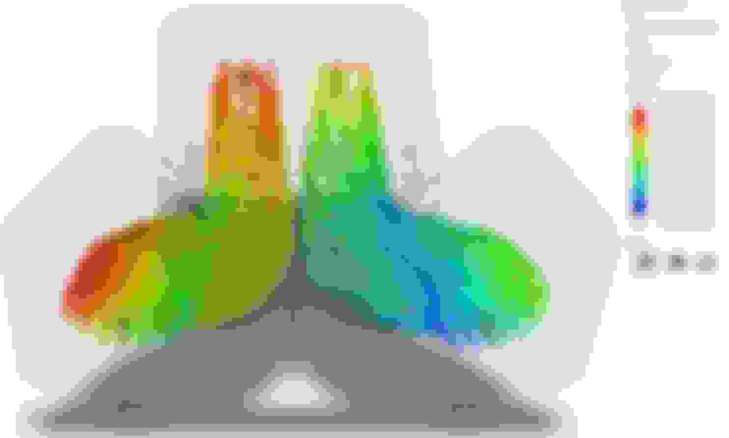
The printfarm at work had some open time this week, so we are moving forward with printing the manifold. Before printing, one of my other buddies was able to run some cfd on the design. We did some iteration to reduce turbulence and flow separation. Luckily we had caught that a part of the design had not mirrored properly. Most of our changes were focused on keeping the flow attached around the first bend.
Previous Previous Final Final
Oil pedestal design, close to final. 10anOrb and two 1/8npt ports. Next iteration will angle the 10anOrb out more towards the front of the engine.
I am trying to keep the oil pedestal a machinable part.
For the sim I found a way to calculate exhaust velocity from the capacity and rpm of the engine. For NA 1.3L at 4500rpm I got 60mph per exhaust port. For lets say 14.7psi boost 1.3L I just treated it as double displacement so 2.6L at 4500 rpm I got 120mph per exhaust port. at 9k rpm those values essentially double.
So for sim parameters we did
velocity = 60mph or 120mph or 240mph
pressure = atm or 14.7psi boost
Gas temp = 1500f to 1800f
Engine flange temp = 500f (just guessed, shouldn't affect much)
Turbo flange temp = 500f (just guessed, shouldn't affect much)
Now if you notice in the sim I had him add a 3inch extension with a slight draft to mimic the initial turbine flow.
I've done some extensive monitoring with an IR thermometer on these flanges, this is a good estimate of a hot setup..... typically after cruise/spirited driving in most FD's and my own car I'm seeing the exterior of these flanges anywhere from 350F to 430F. Of course those are taken immediately after the car is shut down so are likely a bit cooler than if the car is in the middle of sustained WOT driving. This is the downpipe to turbine connection and the turbine to manifold flange I'm measuring. I've tried measuring the flange temp on the block but stopped when it was MUCH cooler than the other two.
Last edited by RotaryMachineRx; Jan 5, 2024 at 12:22 PM.
Well been busy rebuilding an wrx sti for our buddy in the service. He should be ecstatic once he gets back from sandland. I can't believe he didn't blow the engine. Blown headgasket, sparkplugs were like 3x the gap, coils were bloated, timing belt was missing chunks, intake was collapsed just before the turbo, injector wires were hanging on by a thread from strain.
The manifold has been printed at work and is waiting to go into the furnace. I also reached out for casting quotes and the local companies were quoting $6500 for a single or around $3500ea for a10qty..... Seems rather high to be honest. My brother wants to try his hand at casting some day, so this may be a fun summer project.
Also I finished installing the trunk mounted battery.
This was mostly depowdered, which is what you see in the runners.
Forgot to post last weekend, but I did many things that I did not take pictures of. Mainly random touchup stuff on wires and interior. Also I wired and tested the fuel pumps. So far I have the underbody hardlines done and I just made a loop in the engine bay to run the pumps. Both ran and a couple leaks were fixed.
I do have some pics of the:
intercooler install
Radiator planning (ordering now)
Rx8 Oil Cooler thermostat delete. (running a 185c thermostat in the improved racing remote filter unit)
Got a new job, made out like a bandit. working 5 mins from home should save me a lot in gas and premix. Also no more income tax working in NH.
Found a cheap greddy kit for my poverty rat daily rx8..... been dealing with boost creep issues probably due to 3in no cat exhaust.
Building up my spare renesis for the rat rx8.
Testing out some various paint combos to see what I like for engine bay parts.
Got another JDM 5 speed with the help of Fickert
REW update
Finished the 3d Inconel 625 metal print before leaving the old job, see pics below. Had to do quite a bit of mass reduction to prevent sintering issues, reduced from 3.5kg to 2.5kg Inconel. I was hesitant to reduce the t4 flange by much more, even though I probably could have. One runner had a crack that developed during sintering and was welded up. Still need to post machine, tap, and sandblast the part. You can also see a slight layer shift that happened. More pics once i clean it up.
Found out about craftcloud and quoted out a stainless version of the manifold at around $600us per. Plus I would need to post machine and tap.
Started cleaning up the engine harness, contemplating extending to run into the passenger cabin......its rather gooey.
Received my custom radiator from CGJ, should be mounting next.
Made a basic coolant diagram on the google sheet Link Once the radiator is in I can start buying fittings.
Fighting off the horde of mice that are somehow getting into the trunk. I think they are coming up the rear fenders. Stuffed a bunch of dryer sheets in there.
Been working on machining the Inconel manifold. If I have time I would like to get the turbo in the car this weekend, but I may work on wiring.
Also halfway through rewiring the stock harness. I added a pinout table in my google sheets diagrams Link
I haven't talked about it much yet, but I am still having to talk with Adam at REC about the injectors he sold me. He had told me they were ID injectors, but did not include paperwork with them. After checking with ID and 8 other injector companies I still have no idea who modified them. I am probably going to have to buy a new set sadly.
Those look like traditional 3/4 length Bosch EV6 injectors. I would be hard pressed to say those are ID injectors, I'm not aware of any modern ID injectors that aren't the short body with adapters. Even if it is ID, that has to be an old style ID injector. What did REC say was modified about them? The only thing I see is the adapter to get it up to 60mm length.
I must have missed it before but I like the look and placement of your intercooler.
Have you gotten your oil filter pedestal machined yet? I am curious the cost for one.
Yeah they are definitely bosch style, but the part numbers are scratched and other numbers are scratched in. So who knows what they are. Adam had said they were ID 1000 and 2200.
My brother just got his cnc machine operating and is doing some test machining to make my intake elbow throttle body converter. Itll probably be another month before we try to machine the oil pedestal, cuz he just got married and bought a house. I am going to be working on wiring and the fuel system in the meantime. I can get you an estimated cost tho.
Those look like traditional 3/4 length Bosch EV6 injectors. I would be hard pressed to say those are ID injectors, I'm not aware of any modern ID injectors that aren't the short body with adapters. Even if it is ID, that has to be an old style ID injector. What did REC say was modified about them? The only thing I see is the adapter to get it up to 60mm length.
.
My older ID1000's are the 48mm length and I used them without the adapters, when I ordered new ID1050's I had to get adapters to bring the 34mm bodies back up to 48mm to fit my FFE fuel rail. I'm not saying those are ID or not.... just stating that the older ID1000's were the 3/4 length.
On another note, I am almost done with the wiring harness. I just need to hook up
IAT sensor (before Throttlebody)
Ext IMAP sensor (reading up there were a few people that had issues with the internal sensor, so I just got an external one)
Mac solenoid
Wideband.
I find it silly that adaptronic chose to use pins on the 4+5 plug which go to the car and not the engine harness. So I am going to see if I can relocate the IAT and IMAP to plugs 1-3. nope, cant
Originally I did not want to have an actual afr gauge, but it looks like I will have to. MIght just put it in the glove box for now. Any suggestions on where to pass through the firewall? I was thinking opening up the RHD brake booster hole behind the windshield washer bottle. I am not sure if anything sits behind it though....... Maybe i should go to the local junk yard and open up a few holes to try.
Last edited by MincVinyl; Aug 21, 2024 at 06:52 PM.
On another note, I am almost done with the wiring harness. I just need to hook up
IAT sensor (before Throttlebody)
Ext IMAP sensor (reading up there were a few people that had issues with the internal sensor, so I just got an external one)
Mac solenoid
Wideband.
I find it silly that adaptronic chose to use pins on the 4+5 plug which go to the car and not the engine harness. So I am going to see if I can relocate the IAT and IMAP to plugs 1-3. nope, cant
Originally I did not want to have an actual afr gauge, but it looks like I will have to. MIght just put it in the glove box for now. Any suggestions on where to pass through the firewall? I was thinking opening up the RHD brake booster hole behind the windshield washer bottle. I am not sure if anything sits behind it though....... Maybe i should go to the local junk yard and open up a few holes to try.
For AFR I found my Adaptronic internal WB was reading roughly 0.5 leaner than my known good AEM UEGO..... so I ended up pulling a serial cable to feed the Adaptronic the value from my AEM gauge instead.
If you open up your passenger door there is a knockout or two on the frame closes to the front of the car. I pulled a few wires (EGT probes, serial cable, and laptop cable from ECU) up behind the fender, then down into the door sill and through this knockout into the glove box.
Last edited by RotaryMachineRx; Aug 22, 2024 at 10:08 AM.
For AFR I found my Adaptronic internal WB was reading roughly 0.5 leaner than my known good AEM UEGO..... so I ended up pulling a serial cable to feed the Adaptronic the value from my AEM gauge instead.
If you open up your passenger door there is a knockout or two on the frame closes to the front of the car. I pulled a few wires (EGT probes, serial cable, and laptop cable from ECU) up behind the fender, then down into the door sill and through this knockout into the glove box.
Yeah I ran it this way on my other car, but wanted to avoid doing this incase of pinching or overstraining wires.
Well I talked with Mike at REC and he assured me that the injectors would be Bosch's. Apparently its typical for bosch to scratch out the part numbers as they didnt intend these injectors to be used in this application. I still hate that I got them with no packaging or anything.
If anything I will use them to get the engine started and change to ID injectors at some point. I think Ill need 1300 and 2600s if I end up doing E85 anyways.
I used the RHD brake booster hole behind the windshield washer bottle. It did not contact anything and you can route the wires down and into the cab. I actually ran my battery power cable through there.
I had not thought about the passenger door punch-out. Good to know.
I used the RHD brake booster hole behind the windshield washer bottle. It did not contact anything and you can route the wires down and into the cab. I actually ran my battery power cable through there.
I had not thought about the passenger door punch-out. Good to know.
Nice, I will do the same. My plan if I was going to go haltech was to route the ECU through there into the glovebox. I may still go haltech in the end, but right now I just want to get wheels turning with the adaptronic.
Next quick topic. I am planning out all my air/vac tubes.
What did you guys do with your evap line? did you
maintain the rx8 evap solenoid and hook it up to the intake system?
Cap the tube?
One way check valve behind throttlebody
Delete the whole evap system, Saw some people have done this, but I question how the tank vents or vacs out vapors.
Deleted the factory solenoid and capped the line in the engine bay. I believe the tank itself still vents through the charcoal canister nestled between the diff and the bottom of the trunk. My understanding is that the purge solenoid setup is strictly to do with emissions; but beleive me when I say I'm not expert on this system. Mine seems to be issue free to date.
I used the RHD brake booster hole behind the windshield washer bottle. It did not contact anything and you can route the wires down and into the cab. I actually ran my battery power cable through there.
I had not thought about the passenger door punch-out. Good to know.
Do you have to drill this out behind the washer bottle or is there already a hole there?
The door jamb knock-outs are pretty small (wouldn't accepts an entire harness that's for sure). The way you did it is probably a much cleaner way to go.
Do you have to drill this out behind the washer bottle or is there already a hole there?
The door jamb knock-outs are pretty small (wouldn't accepts an entire harness that's for sure). The way you did it is probably a much cleaner way to go.
On mine I would have to drill it out, and the washer fluid bottle has lots of room behind it for harness bends. It almost looks like the washer bottle was designed to look larger, but weigh less.... Or for anti sloshing for those high G window cleaning moments.
I've been toying with the idea of removing my washer bottle and pump anyways to make room for the massive Vibrant catch can I've had in a box for the past 3 years without installing. Unfortunately chasing the issues of my engine not running properly has prevented me from doing and of the minor/fun/less critical modifications I've had planned for a long time.
I use my washer sprayer so much I could never remove it. Mainly from undiagnosed medical issues I get vertigo when my vision is obstructed.
Now this may be a hot take, but almost all catch cans I see are stupid expensive for no reason. Even though they are just a can with steel wool packed in. I dont see much of a difference between lets say the Evil energy Catch can(~$30) and the Vibrant(~$300). I also dont know why you wouldn't use a copper mesh instead to rapidly cool and condense the oil mist for collection, you can get a 5x30ft roll for 10$. I have a couple RV vac pumps I could cut apart one of their oil mist filters, but I am pretty sure they are just metal mesh with a sponge in between.
BTW my current plan for the oil fill neck is to just make a cap plate with a bung on the end to go to a catch can, then to precompressor(vac manifold).