When you click on links to various merchants on this site and make a purchase, this can result in this site earning a commission. Affiliate programs and affiliations include, but are not limited to, the eBay Partner Network.
Side note, that's just a 12V sense so its not loaded right? Just be careful adding additional load on the the wires of the fuse box. One of mine is toasted from added a 20amp fuse to a 15 years ago and didn't see it until now.
The line on the "add-a-circuit" is the Lamp line. I can't imagine it is producing much for load since it is literally for lighting up a light bulb if voltage is too low. But I'm pretty green when it comes to electrical (but I'm learning a lot as this project throws things at me) so I don't truly have much for an "educated" answer haha.
So got to dismantle my engine to possibly salvage the e-shaft. Note the engine ran fine, no hot start issues, and compression was front high 80's (I think 92 was the highest), but the rear was mid 70's. Thought it was just a seize seal from carbon possibly. Well not quite.
The rear chamber definitely had borrowed time I think, with the corners of the apex seals eating away at the housings pretty heavily and beginning to fall out of the rotor. No excessive chatter or wear anywhere else really. A shame, I was fairly confident both of the housings would be in good shape to resurface and sell. Oh well. I did end up getting the eshaft out and cleaning up for inspection tomorrow. I did accidentally put a few small horizontal marks on the front rotor bearing surface. I am going to try to carefully take some emery paper and wear down any sharp edges (barely any at all) from my mistake. If I don't like it a new eshaft is not the worst purchase of the build...
Sorry for the huge images, I even cropped them, but they're still massive. Rear rotor housing damage.
Rear rotor corner of apex seal on the left, front rotor corner of apex seal on the right.
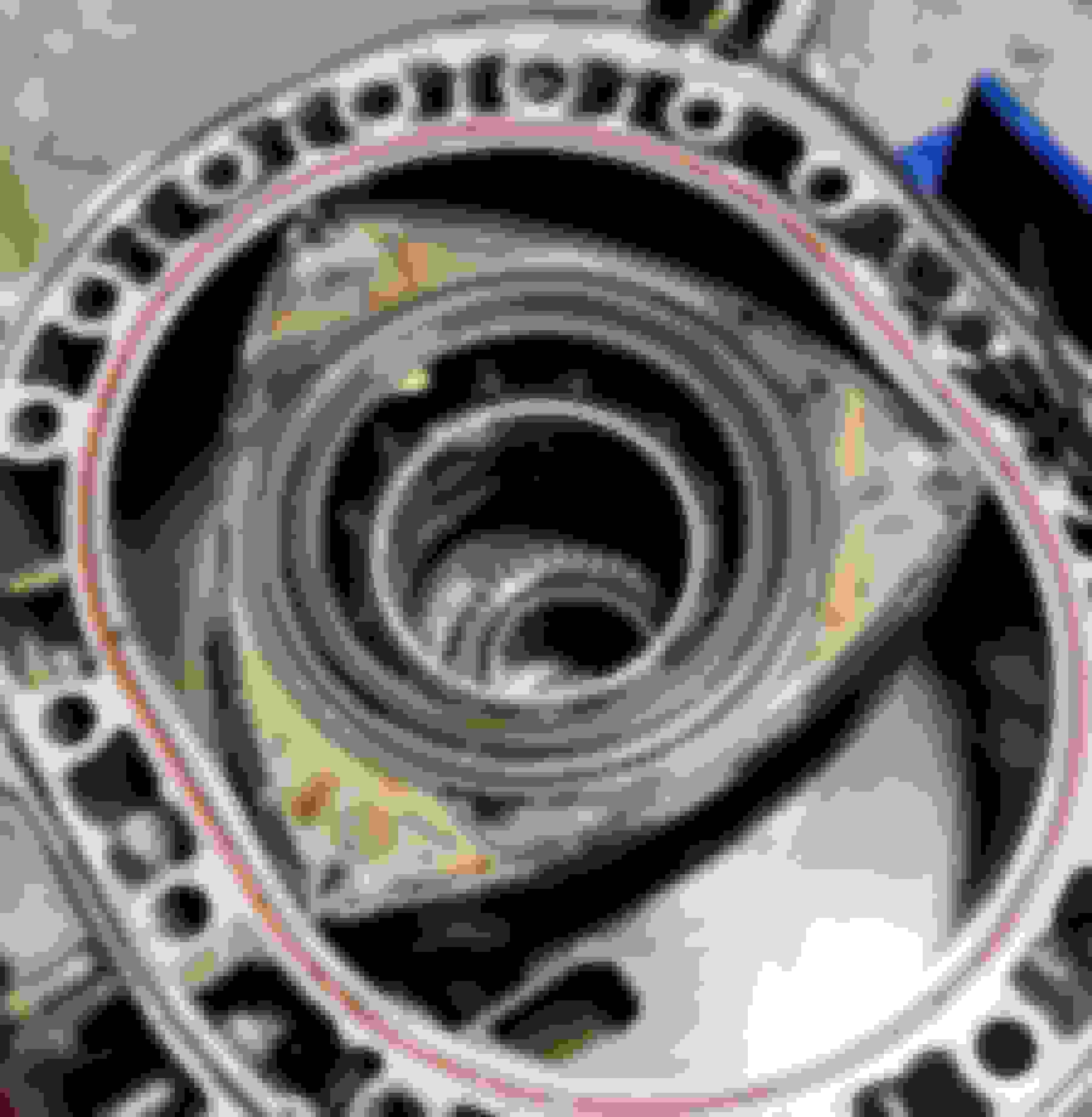
Curious if anyone has an explanation for this flow pattern? I was originally thinking it was the flow of the exhaust going around the scalloped edges but now I am thinking I'm wrong.
Carbon build up in the exhaust ports really wasn't that bad, definitely seen worse.
sandy gunk I found in the bottom of the coolant passage.
Finally, can go check the eshaft for concentricity tomorrow on our granite block.
The line on the "add-a-circuit" is the Lamp line. I can't imagine it is producing much for load since it is literally for lighting up a light bulb if voltage is too low. But I'm pretty green when it comes to electrical (but I'm learning a lot as this project throws things at me) so I don't truly have much for an "educated" answer haha.
Probably not wrong really. When you get it back up and running it would be easy to break the circuit to the fuse box for that wire and measure current with a meter. It realistically should be low. Probably just enough to energize whatever relay is in there.
keep rotating it toward the intake until it lines up exactly with the exhaust port opening � (TDC of the intake cycle)
.
I'll have to set it back up tonight to understand more. Was just surprised to see a pattern like this on the sides. Thought the side seals prevented much of this? But again with side exhaust ports it would kinda make sense then.
no, that side surface of the rotor travels right over the exhaust port opening as the rotor rotates. It’s the first cut-off seal to the inside and the close shape of the rotor tip side that attempts to keep the exhaust gasses from moving from the exhaust port to the intake ports.
so when you go look at the hybrid build that Kyle Mohan is milking for all it’s worth, he did the 13B mod of milling the rotor tips down to lighten and clearance them. That works on a 13B engine without side exhaust ports, because the hot exhaust gasses going out the peripheral exhaust port has no contact to the rotor sides due to the side seals as you’re thinking.
But on the side exhaust port Renesis, the side of the rotor tip and side seal transitions over the exhaust port opening directly exposing the rotor tip side to the exhaust gasses, except now with the milled out modification that opened area forms a cavity to fill up exhaust gas and is then going to transfer it right over into the intake ports reversing flow and diluting the incoming charge.
Mazda intentionally filled that rotor tip area in on the Renesis, moved the side seal outward toward the rotor face, and added the cutoff seal to mitigate all that. Not just for emissions, but for performance too.Because the Renesis Pri & Sec intake ports are positioned much further over to the opening side very early intake cycle than on those previous 13B engines. You can’t even port a 13B Pri & Sec to open that early except by adding a bridgeport opening and that’s not really the same thing as having the full port open like it does on the Renesis. Yet unlike a bridgeport, the Renesis idle and low speed driveability aren’t heavily impacted thanks to no overlap or exhaust gasses not backflowing into them.
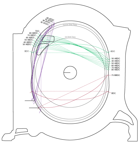
It’s too bad you tore it down fully, because if you can rotate the rotor and watch how and where the rotor edge interacts with the ports then that helps to understand how it all works going from cycle to cycle. Some people can’t envision it well enough in their head. The exhaust port opens at the wide bottom end edge of the opening up until the pointy top end is exposed and the port fully open. It then closes from the side edge from the center over to the outer side edge closest to the rotor housing. The intake ports are the opposite; opens at the long side edge closest to the rotor housing over to the side edge on the center side to then be fully open. It then then closes starting at the bottom edge of the port on to the top side edge.
The key feature to the side ports being they open in one sweeping direction, but close in a different/opposite sweeping direction. Whereas a peripheral port always opens on the bottom and closes on the top in the same sweeping direction.
Team thanks for explanation. I believe I understand your explanation, but agree my head is having a bit of difficult time seeing it.
Originally Posted by TeamRX8
It�s too bad you tore it down fully, because if you can rotate the rotor and watch how and where the rotor edge interacts with the ports then that helps to understand how it all works going from cycle to cycle. Some people can�t envision it well enough in their head. The exhaust port opens at the wide bottom end edge of the opening up until the pointy top end is exposed and the port fully open. It then closes from the side edge from the center over to the outer side edge closest to the rotor housing. The intake ports are the opposite; opens at the long side edge closest to the rotor housing over to the side edge on the center side to then be fully open. It then then closes starting at the bottom edge of the port on to the top side edge.
The key feature to the side ports being they open in one sweeping direction, but close in a different/opposite sweeping direction. Whereas a peripheral port always opens on the bottom and closes on the top in the same sweeping direction.
Good thing is the front plate is still on the engine stand with the stat gear, Just need to to put a rotor back on and the eshaft to replicate the cycle. Definitely work exploring/understanding for my own sake.
That's about as good as an explanation of the side ports open/closing as I've seen. Even with such a great description.... it really doesn't click until you can see it illustrated for yourself; at least for me, that was a moment of epiphany lol
Is there any chance you could sprout a 3rd hand to record this? I�m part of the population that Team is referring to when trying to visualize the port opening/closing. Thanks.
Is there any chance you could sprout a 3rd hand to record this? I�m part of the population that Team is referring to when trying to visualize the port opening/closing. Thanks.
I wish I could, I left my eshaft at work. Apparently our v-blocks are super rusted so measuring woulda been useless. grabbing mine from home and measuring tomorrow. But the rotor and front plate are mounted ready to see this. I can hopefully get my wife to get a video of it. Hopefully I can understand it and try to narrate, likelihood is no though.
Didn't expect it to be out of spec, but wanted to verify. E-shaft is well within spec of 2.4 thou; only read 1 thou of runout.
Next up will be checking rotor to housing clearance. Probably knock this out at lunch. Having access to a lathe will make this easy if there are issues.
Also contemplating race clearance the rotors along the tips. I think RB says 0.5 thou from each side removed is a good enough amount. only "necessary" for 8500 rpm and above, but I am just thinking more of why not.
And while on the conversation of rotors, I noticed this the other day. Two of my rotors have flat faces, but one of them has a raised ring near the oil control rings. The problem is the two rotors I was planning on using are different; the third that is also flat has a small detonation cavity formed in it and would like to avoid using it. I guess I could measure the corner seal depths to the faces and see if there is a difference of what the ring height is. If the difference is there I could just turn the ring into the other rotor. I assume the ring feature is just to help prevent the rotor from contacting the irons, unless there is more to it? no ring raised ring detonation
I think I'm going to get my rotors raced clearanced as well for my rebuild, just a little extra safety factor even though I don't intend on going over 8500rpm either.
As for the raised ring..... are you talking about the ring around the outside of the rotor gear? I can check my spare rotors I have in my garage and see if I notice anything similar, but what you're saying is if you hold a straight edge across the rotor that ring is preventing the straight edge from touching the side face of the rotor?
I think I'm going to get my rotors raced clearanced as well for my rebuild, just a little extra safety factor even though I don't intend on going over 8500rpm either.
As for the raised ring..... are you talking about the ring around the outside of the rotor gear? I can check my spare rotors I have in my garage and see if I notice anything similar, but what you're saying is if you hold a straight edge across the rotor that ring is preventing the straight edge from touching the side face of
the rotor?
Kinda my thought. I am surrounded by pretty seasoned machinists here at work that are more than happy to help me run the lathe and machine them myself. Also the reason I am doing 1/2 studs.
To your rotor question about a straight edge, yes, see this image I added to show the visible ring.
Originally Posted by TeamRX8
it appears to have been milled already (notice no balancing hole), but with a detonation dent you might as well toss it.
.
Sorry I was a bit unclear;
- x1 rotor without ring
- x1 rotor with ring
- x1 rotor without ring, detonation dent
Also quickly searching I am more on the lines of this is a modern update Mazda has made. Mazdatrix's photo for a new REW rotor also shows the ring in it. You have to look carefully though. So likely no previous machining/balancing. Just a newer rotor.
Thanks for the updated photo, I was totally looking in the wrong spot. Anyways, now that I see it I can check my spare rotors tonight and see what is there.
Ultimately will it even matter? The sideseals, corner seals, and OCR's should stick out taller than that ring anyways?
I mean I have both right in front of me and a pair of mics.
Measuring both rotor types, they both measure 3.133" at the normal surface. And the ring surface is 3.138". So the ring surface per face is 0.0025" taller than the base surface.
But I am not sure where I can find nominal width measurements of rotors. Service manual only cares about clearances between the housings and rotors (makes sense).
Already measured the two rotors that don't have detonation for clearancing. I also measured both housings. The rear housing the idiot spray painted it all but the housing surface silver -.- so I assume the paint will mess with the width a bit. maybe a half thou or so. I will get acetone and remove the paint and recheck.
#1 rotor combined with Rear housing (painted) = 0.005" clearance; pass
#2 rotor combined with Front housing = 0.0065" clearance; pass
So the painted housing could be a bit tight if I remove the paint. Definitely will have to check it again. Also all parts are normalized to atm temp. Sat in our office for a few days now.
Thanks for the updated photo, I was totally looking in the wrong spot. Anyways, now that I see it I can check my spare rotors tonight and see what is there.
Ultimately will it even matter? The sideseals, corner seals, and OCR's should stick out taller than that ring anyways?
Honestly I don't think it will now looking more into it. But something I caught and was curious if anyone else had info on it.
Back to the ring of the rotor, I think I have a theory. The rotor is balancing itself between the clearance of the bearings and e-shaft, but there still should be some room to tilt. The oil control rings and springs, side seals and springs, and corner seals and springs should keep the rotor somewhat balanced, but if they start to get overtaken with rpm or load, they can compress far enough to where the actual rotor makes contact with the side plates. Maybe this ring is a sort of solid "stop" to prevent a majority of the rotor from touching the side plates. Kinda like a bump stop for suspension.
probably again looking too much into it. Just something to get me through the day I suppose.