S2 oil injection info/SOHN style adaptor
#1
S2 oil injection info/SOHN style adaptor
Hi guys,
Im currently building an mx5 and using a s2 rx8 engine as the heart of the build.
Im using an adaptronic ecu to control the ssv etc in the inlet so I have a single spare linear voltage output to use, I'll be designing and making a "box of tricks" to pickup on this signal and tell the oil injectors what to do.
I've read all I can read on the subject without any hands on/physical data, so im asking for a bit of help to finalise the design.
I've read that the pressure to the motors is a maintained 6-20psi, is this constant throughout the Rev range? As that will simplify things as I can use a fixed pressure pump. If it is, how is the amount of oil injected controlled? As its my understanding that the solenoids are exactly that, open of closed.
Do oil injectors inject at different stages or do all 3 inject simultaneously in the rotor housing? (I assume the later to be true as they have an oil return after the second solenoid)
I'll be designing a controller, possibly arduino based or some form of micro controller with basic logic, a bypass for the oil supply tee, and a plug for the oil way solenoid on the front casing. The tee bypass will allow me to run a pressurised feed from a 2 stroke tank with a warning light to let me know when the level is low, fortunately I have a spare washer bottle warning light on the 5 dash that isn't used, on an rx8 it would be wired to the oil pressure light or a separate led.
I have an engine here that I can get running in premix but as its not running in standard guise I can't get any of the oil pressure data or signal data from the ecu, if anyone can measure these things then I'll be very much appreciative.
Last edited by JoshRx5; 06-02-2016 at 03:24 AM.
#3
Because there was no donor car and getting those parts from a breaker is a lot of cost, is it's easier to go standalone as I can keep the looms separate.
I just need the answer to the oil injection bits and that's all areas of the build complete
I just need the answer to the oil injection bits and that's all areas of the build complete
#4
New Member
Join Date: May 2016
Location: charlotte NC
Posts: 17
Likes: 0
Received 0 Likes
on
0 Posts
The OMP pump uses a a stepper motor that rotates a cam that control the position of the metering needles to allow oil passage under pressure. The cam position sensor tells the ECU where the cam is as feedback for system control.
If i was building this setup I would bench test the flow on a linear scale using RPM to control stepper motor position proportionally. Then I would account for ambient temp and engine temp (cold start-up) to increase flow through warm up.
I would bench test this set up first simulating an RPM feed and a temp feed to control the stepper motor and measure actual oil flow, before installing on the engine. Hope this helps.
#6
Where is the stepper motor that regulates the pressure?
The two solenoids on top from my understanding of this thread: https://www.rx8club.com/series-ii-technical-trouble-shooting-160/inside-emop-2-a-207735/
Is that the two EMOP's are just solenoids, so either open of closed? A plunger pushes down on 4 pins to open up the feed to the injectors.
On the front of the s2 engine there is a barb which is obviously the feed to the EMOP's and in front of that there is another solenoid which allows the oil from the sump into the oilway for the EMOP's.
Or is it as simple as as the revs rise the engine pressure rises and therfore the pressure released to the EMOP circuit rises??
Sorry if it's me asking a lot of questions, I just can't figure out where a cam/stepper combo is on the s2 setup?
#7
New Member
Join Date: May 2016
Location: charlotte NC
Posts: 17
Likes: 0
Received 0 Likes
on
0 Posts
My apologies, I assumed you were dealing with a series I RX-8 motor. The series II uses a much simpler setup that involves a solenoid versus a stepper motor and a cam position sensor (it is actually a TPS from a 929 or 626 I think).
I am sure the solenoid is a variable rate type using voltage / duty cycle to control how far does the plunger travel.
I still would use the same approach of bench testing this setup using RPM and temp for a linear proportional control relationship.
I am sure the solenoid is a variable rate type using voltage / duty cycle to control how far does the plunger travel.
I still would use the same approach of bench testing this setup using RPM and temp for a linear proportional control relationship.
#8
I did post it in the s2 section and title it s2 oil injection haha!
Im still not seeing where there is a cam and a tps to sense this cam? The solenoids being variable might make sense, this is why I need someone to grab a multimeter and physically test them, see if the signal at the plug is a straight 12v or a rising rate signal.
Im still not seeing where there is a cam and a tps to sense this cam? The solenoids being variable might make sense, this is why I need someone to grab a multimeter and physically test them, see if the signal at the plug is a straight 12v or a rising rate signal.
#9
New Member
Join Date: May 2016
Location: charlotte NC
Posts: 17
Likes: 0
Received 0 Likes
on
0 Posts
Josh, sorry for creating this confusion, the series one used a stepper motor and position sesnor setup.
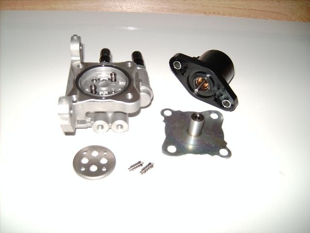
Series two uses only a solenoid and a plunger that presses on a plate that moves the oil metering needles. Totally different setup. No stepper motor and no position sensor in series two.
Series two uses only a solenoid and a plunger that presses on a plate that moves the oil metering needles. Totally different setup. No stepper motor and no position sensor in series two.
#10
Okay not to worry,
Leads me back to the original question thoigh, and that is does anyone know how the 7-20psi oil pressure is regulated or how the amount of oil entering the rotor housing is controlled?
Leads me back to the original question thoigh, and that is does anyone know how the 7-20psi oil pressure is regulated or how the amount of oil entering the rotor housing is controlled?
#12
New Member
Join Date: May 2016
Location: charlotte NC
Posts: 17
Likes: 0
Received 0 Likes
on
0 Posts
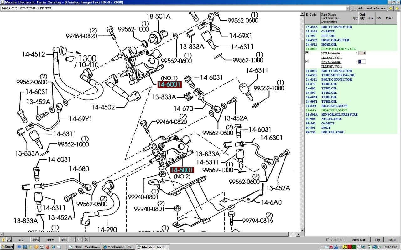
Image of the metering pump series II.


