
DIY: Restoring Clock and Ambient Temp via OBD2 and Stock Deck


DIY: Restoring Clock and Ambient Temp via OBD2 and Stock Deck
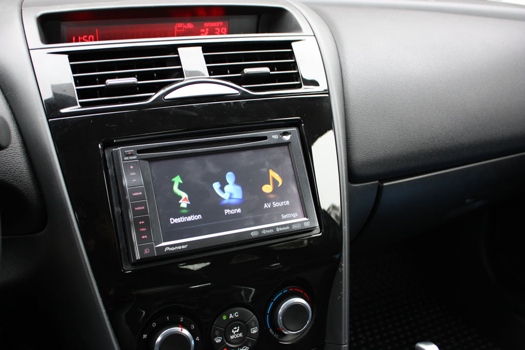
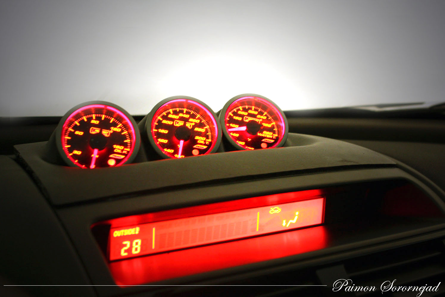
For those of us with S2's that have replaced our stock stereos, we run the risk of losing some of the OEM functionality of the information display (MID). Once a battery reset happens, S2 owners lose their clock, and their temperature display moves to the far left of their MID. Although this may not be a big deal for some, it really bothered me, especially the fact that it would show no more than 70F. After getting my hands on some schematics, I decided to start coming up with an easy way to go ahead and set the clock. As a side project, I am working on an Arduino based solution that, if it works, I will distribute among members, but for now, this solution does just fine.
Requirements
* Stock stereo
* Open Ended OBD2 Cable
* Telephone wire Butt End Connectors
* 18 Gauge Connectors
Links To Items
* http://www.amazon.com/OBDII-Cable-J1...f=pd_rhf_p_t_1
* http://www.radioshack.com/product/in...LAID=107591898
* http://www.radioshack.com/product/in...ductId=2103510
What we are trying to resolve
Last edited by paimon.soror; May 31, 2011 at 05:15 PM.
To start, we are going to need a few wiring diagrams, these can easily be found online.
The following is the audio harness for most Mazda models 2006 and up. There are only 6 pins we need to worry about.
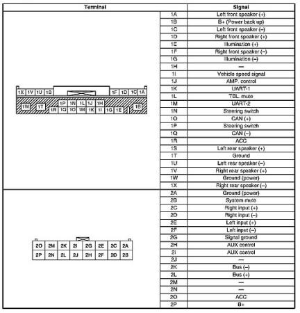
Make note of the following pins:
1. Power 1B
2. Acc 1R
3. Can + 1O
4. Can - 1Q
5. Signal Ground 1W
6. Power Ground 1T
The next schematic that we need to make note of, is the wiring diagram for the OBD2 cable that we purchased from Amazon. Please note, there is a chance that another cable will have a different wiring scheme. These wires should abide by the standard, however, double check.
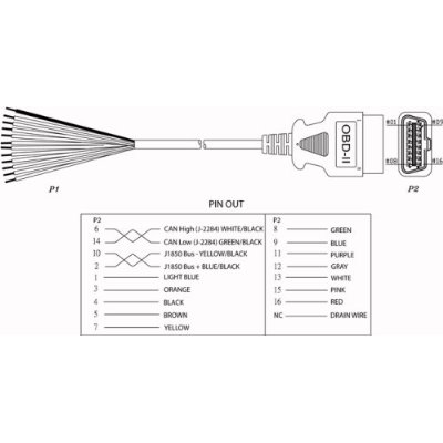
Make note of the following wires:
1. Red
2. Black
3. Orange
4. Purple
The following is the audio harness for most Mazda models 2006 and up. There are only 6 pins we need to worry about.
Make note of the following pins:
1. Power 1B
2. Acc 1R
3. Can + 1O
4. Can - 1Q
5. Signal Ground 1W
6. Power Ground 1T
The next schematic that we need to make note of, is the wiring diagram for the OBD2 cable that we purchased from Amazon. Please note, there is a chance that another cable will have a different wiring scheme. These wires should abide by the standard, however, double check.
Make note of the following wires:
1. Red
2. Black
3. Orange
4. Purple
Last edited by paimon.soror; May 31, 2011 at 05:18 PM.
The next thing we want to do is to prepare the OBD2 wire using the butt connectors. The first thing I did, was cut down the cable from its original size, to roughly 1.5-2ft. This way I dont have a massive slack of cable to carry around. Second, I snipped off all wires that I didn't need, and only left the 4 that I had mentioned above.

Once you have snipped and trimmed the wires, you want to attach a telephone butt connector to the red, purple and orange connectors. Make sure you crimp these down nice and tight.

Once you have done this, you need to grab one of your 18 gauge connectors, and test fit one of the ends to the 1W location on the back of your radio. The reason you need to do this is because the pin is actually a wider pin and not a round standard pin. I had to take the end of the connector and flatten it a bit so it would slide onto the pin. Once you have done this, crimp the other end to the black wire.
Once you have snipped and trimmed the wires, you want to attach a telephone butt connector to the red, purple and orange connectors. Make sure you crimp these down nice and tight.
Once you have done this, you need to grab one of your 18 gauge connectors, and test fit one of the ends to the 1W location on the back of your radio. The reason you need to do this is because the pin is actually a wider pin and not a round standard pin. I had to take the end of the connector and flatten it a bit so it would slide onto the pin. Once you have done this, crimp the other end to the black wire.
Last edited by paimon.soror; May 31, 2011 at 05:21 PM.
Now that you have your OBD2 cable ready, we are ready to hook it up to our stereo. The wiring MUST MATCH the following:
-- OBD2 -- || -- Radio --
Black || 1W
Black || 1T
Red || 1R
Red || 1B
Orange || 1O
Purple || 1Q
Note: You will see that the Red and the Black wires go to two locations. You want to use whatever method you can to do this! What I did was took a wire Tap and added an extra wire to the red and black.

Once you are done, plug it into your OBD2 port. You will hear the cd drive make some noise, as this is a normal startup noise after being unplugged. If you do not hear the noise, make sure that your ground and power are properly connected. If all is well, turn your car to ACC and you should see the clock pop up. Set your clock, then turn the ignition back to "off", and remove the cable. Now turn the car to the "ON" position, and you should now have your clock and your temp display!!

-- OBD2 -- || -- Radio --
Black || 1W
Black || 1T
Red || 1R
Red || 1B
Orange || 1O
Purple || 1Q
Note: You will see that the Red and the Black wires go to two locations. You want to use whatever method you can to do this! What I did was took a wire Tap and added an extra wire to the red and black.
Once you are done, plug it into your OBD2 port. You will hear the cd drive make some noise, as this is a normal startup noise after being unplugged. If you do not hear the noise, make sure that your ground and power are properly connected. If all is well, turn your car to ACC and you should see the clock pop up. Set your clock, then turn the ignition back to "off", and remove the cable. Now turn the car to the "ON" position, and you should now have your clock and your temp display!!
Last edited by paimon.soror; May 31, 2011 at 05:27 PM.

Registered
Joined: Sep 2004
Posts: 590
Likes: 3
Good write up. May I suggest something?
I know this is a budget project and people probably don't want to spend to much on resetting their clock but you could also look into one of these harnesses and just wire the OBDII cable up from there. If there are any missing pins (such as for the CAN wires), just depin the connector from and move the pins necessary. It would make for a very nice plug in adapter.
http://www.amazon.com/Scosche-Ma03Rb...d=4MX54CGGCTI6


No problem. For what it's worth I am currently working on creating an ardunio based solution for display text on the MID sort of like how the metra allows you to for the S1. I will keep you guys posted and will display my discoveries in another thread.

Registered
Joined: May 2011
Posts: 6
Likes: 0
Paimon,
What all will this do? Put clock on left and temp on right? Show true outside temp not just up to 70? If shows outside temp, how do you switch between outside temp and AC/Heat setpoint? Is this something that can be left hooked up and tucked in glovebox so time can be reset with time change?
Sorry if these question are noob questions but I don't understand the electronics like you guys do and I only had my 8 for not even 2 weeks.
Lastly, any chance you can show me how to hookup the hood to the battery so is will act like a shock collar when my cat jumps on it?
This will restore the OEM lcd display. For those series 2 owners that have changed their stock headunit to an aftermarket one, a battery disconnect will remove the clock from teh display and move the ambient temperature reading to the left
The AC/Heat controls will still display in their normal position whether you do this bypass or not
Sure, the actual face of the radio detaches from the rest of the device. By doing this you are left with a small box that can easily be placed in the glove box. The only thing you would have to do when you want to set the time is to pop the face back on so you get access to the hour and minute controls.
Is this a serious question..... 
Registered
Joined: May 2011
Posts: 6
Likes: 0


Registered
Joined: Jul 2011
Posts: 61
Likes: 0
What if you do not have the stock head unit? My car came with an aftermarket Alpine and this issue.
Am I just waiting for this other solution unless I want to buy an old radio? If so, when please?
Also, you never mentioned if the fix would correct the outside temperature to above 70.
And for people in cooler climates, is it accurate below 70? I live in central texas and assumed that it ONLY displayed 70 as it isn't getting below that any time soon or recent here.

Hey sorry man, missed this
So far the only other remedy I have found is through a circuit that I am developing (found in my sig) to manually send the appropriate commands along the MSCAN bus.
Also, you never mentioned if the fix would correct the outside temperature to above 70.
And for people in cooler climates, is it accurate below 70? I live in central texas and assumed that it ONLY displayed 70 as it isn't getting below that any time soon or recent here.
Yup, the fix moves the temp back to the righthand side and will operate per normal. And it is accurate below 70 when the temp is showing on the left like yours. I have read all the way down to -5 that way, just doesn't go above 70 for some reason.
Trust me the first time I noticed that it was annoying as hell because for like 3 days in a row i got out of work, sweating sack in my car and i look and its only 70 and im like 'wtf' ... turns out it was really high 80's lol
Also, you never mentioned if the fix would correct the outside temperature to above 70.
And for people in cooler climates, is it accurate below 70? I live in central texas and assumed that it ONLY displayed 70 as it isn't getting below that any time soon or recent here.
Trust me the first time I noticed that it was annoying as hell because for like 3 days in a row i got out of work, sweating sack in my car and i look and its only 70 and im like 'wtf' ... turns out it was really high 80's lol

Registered
Joined: Jul 2011
Posts: 61
Likes: 0
Well that project looks outstanding. On the one hand, I am anxious to get my display straightened out. On the other, this has flat amazing potential.
I know some programming, but am not familiar with CANBUS at all and not much more than reading an OBD scanner. If there is anything I can do to help, though, I am willing.
1. Could you build a "self test" type button where it scrolls through some of our favorite systems to make sure they are ok (without going through the trials of Hercules and/or a divorce - and that applies to all feature request notes - not is it theoretically possible, but is it within reach)?
2. Could it read oil level from the same sensor that drives the "idiot light" and give us a better reading of the oil level (not sure if this data is in there or not)?
3. Can it read the TPMS and show us actual tire pressure on each tire? I understand the system itself is normally accurate to within 2psi, which is pretty good. Once again, we just get an idiot light.
At that point, I would make it a permanent fixture in my car.
Registered
Joined: Jul 2011
Posts: 61
Likes: 0
Come to think of it, if you had to do it over, what would you do differently, if anything, parts wise? Is there a "dual CANBUS" card instead of stacking those two, for example?
I may start on this myself, if you do not mind sharing your knowledge a bit.
I may start on this myself, if you do not mind sharing your knowledge a bit.
Well that project looks outstanding. On the one hand, I am anxious to get my display straightened out. On the other, this has flat amazing potential.
I know some programming, but am not familiar with CANBUS at all and not much more than reading an OBD scanner. If there is anything I can do to help, though, I am willing.
1. Could you build a "self test" type button where it scrolls through some of our favorite systems to make sure they are ok (without going through the trials of Hercules and/or a divorce - and that applies to all feature request notes - not is it theoretically possible, but is it within reach)?
2. Could it read oil level from the same sensor that drives the "idiot light" and give us a better reading of the oil level (not sure if this data is in there or not)?
3. Can it read the TPMS and show us actual tire pressure on each tire? I understand the system itself is normally accurate to within 2psi, which is pretty good. Once again, we just get an idiot light.
At that point, I would make it a permanent fixture in my car.
I know some programming, but am not familiar with CANBUS at all and not much more than reading an OBD scanner. If there is anything I can do to help, though, I am willing.
1. Could you build a "self test" type button where it scrolls through some of our favorite systems to make sure they are ok (without going through the trials of Hercules and/or a divorce - and that applies to all feature request notes - not is it theoretically possible, but is it within reach)?
2. Could it read oil level from the same sensor that drives the "idiot light" and give us a better reading of the oil level (not sure if this data is in there or not)?
3. Can it read the TPMS and show us actual tire pressure on each tire? I understand the system itself is normally accurate to within 2psi, which is pretty good. Once again, we just get an idiot light.
At that point, I would make it a permanent fixture in my car.

Bringing this back from the dead but my stock headunit (OEM) does this in my S2. It shifted the temp to the left and I've lost all functionality and time. Is there a specific wire or loose connection I should be looking for ? I pulled the headunit and couldn't find anything loose behind it but maybe I missed it...?
Are you seeing the volume controls on the information screen anymore? Or any radio information? Without knowing much more it sounds to me like the CAN controller on your head unit stopped communicating to the network. (when you plug in the radio it sends a message across the network when you first turn on to initialize the clock, if this message doesn't get sent, the clock's position is replaced w/ the temp)