
How to Scale your MAF for Flash Tuning (Cobb, Hymee)


Registered
Joined: Aug 2007
Posts: 29
Likes: 0
Any changes to the intake will throw off MAF scaling. Maybe not enough for Mazda to require a reflash for the MS intake on a stock RX8. But with forced induction and greater air flows, the error will be amplified. We discussed this before but ideally you want to tune the MAF with stock injectors, then add the bigger injectors and tune them. Changing injector scaling and MAF scaling concurrently will cause you to chase your tail since both variables affect AFRs. Can you calibrate the MAF with airflow data alone (no AFR)?

U-Stink-But-I-♥-U
iTrader: (1)
Joined: Mar 2005
Posts: 2,004
Likes: 2
From: 12 o'clock on the Beltway.
Yeah, your point also came up in Jeff's tuning webinars. While I could have swapped back in the stock yellow injectors, I was too lazy. But you are right, doing both maf and injectors on the same flash is a complete mistake, unless you are just throwing a guess out there to start off.
The MAF could be calibrated on a flow bench of sorts, but I dont have an independent airflow meter, nor can think of a way to make one.
The MAF could be calibrated on a flow bench of sorts, but I dont have an independent airflow meter, nor can think of a way to make one.
3-wheeler
Joined: Dec 2005
Posts: 2,734
Likes: 1
From: Phoenix
You can tune using both MAF calibration and injector scaling but it's knowing when to use them and when not to. The MAF can provide a fine tuning aspect and allows you to change air/fuel within certain airflow regions.
The injectors are a much broader correction. If you have a situation where you're lean across a wide area you can scale your injectors to add more fuel.
They key is knowing which tool in your belt to employ otherwise, as you said, you'll be running in circles.
The injectors are a much broader correction. If you have a situation where you're lean across a wide area you can scale your injectors to add more fuel.
They key is knowing which tool in your belt to employ otherwise, as you said, you'll be running in circles.


Good points all - that is one of the reason I do 2D and 3D tuning.
If your 2D is showing consistant errors in a certain AF range - then it is safe to make MAF changes - if your tune just has some small holes in it; injectors might do it; or the base fuel map.
If your 2D is showing consistant errors in a certain AF range - then it is safe to make MAF changes - if your tune just has some small holes in it; injectors might do it; or the base fuel map.
U-Stink-But-I-♥-U
iTrader: (1)
Joined: Mar 2005
Posts: 2,004
Likes: 2
From: 12 o'clock on the Beltway.
The issue that I posted a while back concerning two "levels" of AFR at one load is resolved. Again I am not completely sure what specific adjustment fixed it, but this is my new AFR vs Load graph:
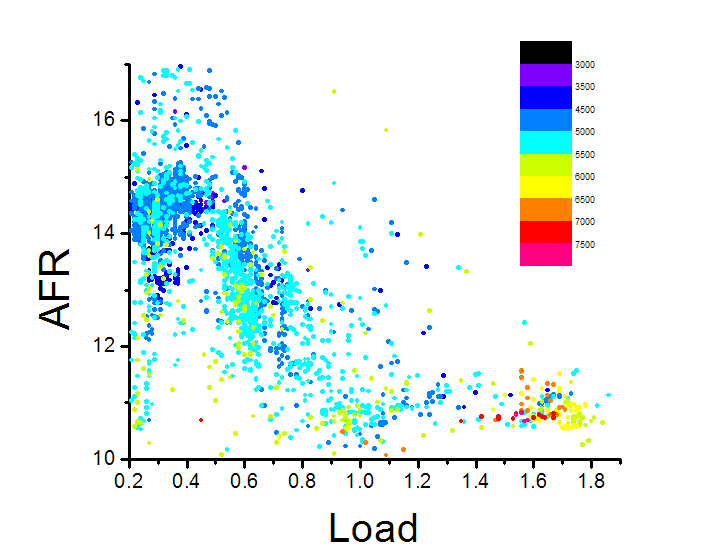
You can see that with increasing load, I have decreasing AFR, all in reasonable amounts. This plot helped me visualize not only if I was hitting my target AFRs (which Kane's software analyzes) but also helps to make sure that there are no non-normal (non-gaussian) distributions at any particular load.
You can also see that with increasing RPM I have steeper increases in AFR. This was intended.
Now the current issue that I am having is with the scale of my injectors. I installed a new bank of injectors (Siemans Deka; 650 cc/min) and just guessed (with the percent difference function) what the new scalar should be in the ATR software. Having played with this number, I am confident that increasing this number will lead to leaner AFRs and that decreasing this number gives richer AFRs. (I.e., if the computer thinks that the injector is smaller than it really is, the computer will increase the dc and add too much fuel and vice versa.)
Jeff (MM) has posted a rough outline of how the injectors come on line.
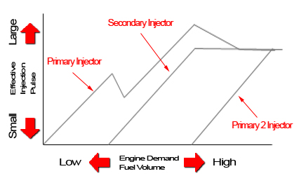
I dont really know what the axes are but the general idea is obvious.
The question that has arisen several times, both here and during Jeff's webinar is given the influence of both the MAF calibration and the injector scaling on AFRs, how do you scale either independent of the other.
The answer has been that you can not. One should scale the bigger injectors on a stock intake then install and calibrate the aftermarket intake (or, if the stock injectors are perfectly scaled, vice versa.)
Well, I am just not going to go backward and do that. I reasoned that any mis-scaling of the injectors would show up in the MAF calibration curve as "bumps" or systematic excursions from a theoretical calibration curve. For instance, if the calibration curve is smoothly increasing then abruptly alters its shape, what this really means is not that there is a sudden change in airflow with a small increase in volts, but that at this particular TRUE airflow one of the injectors is mis-scaled and that the computer must be LIED TO telling it that more or less airflow is availible so that it increases or decreases the fuel availible to compensate for the error in the injector scaling.
Using the method that I decribed above, I iteratively scaled my MAF calibration until my measured AFRs were close to my target AFRs. What I noticed is that as the voltage increased, the air flows abruptly jumped at two distinct points. Below is my plot of adjusted airflows vs MAF volts with the MAF calibration curve. Note that I adjusted the MAF calibration curve (red points) several times prior to this graph. This graph is not showing ANY adjustment to the MAF curve but is showing how close my adjusted curve is to the curve that is in the ATR software.
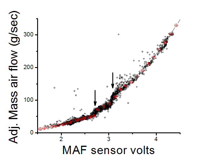
I hypothesize that my injectors are scaled too large. Once the bank two injectors start to kick in the pcm has to be lied to telling it that there is MORE air coming in than there actually is. The computer responds by increasing the dc of the injectors to meet the need of the increased airflow. What I think that I need to do is decrease the scalar of both the sec and p2s and then recalibrate the MAF. The question is by how much?
I should mention the method that I used to scale the primaries. I simply kept the stock MAF calibration from 2-20 g/s (idle airflow is 5 g/s) and scaled the primaries until my LTFT at idle was 0.
You can see that with increasing load, I have decreasing AFR, all in reasonable amounts. This plot helped me visualize not only if I was hitting my target AFRs (which Kane's software analyzes) but also helps to make sure that there are no non-normal (non-gaussian) distributions at any particular load.
You can also see that with increasing RPM I have steeper increases in AFR. This was intended.
Now the current issue that I am having is with the scale of my injectors. I installed a new bank of injectors (Siemans Deka; 650 cc/min) and just guessed (with the percent difference function) what the new scalar should be in the ATR software. Having played with this number, I am confident that increasing this number will lead to leaner AFRs and that decreasing this number gives richer AFRs. (I.e., if the computer thinks that the injector is smaller than it really is, the computer will increase the dc and add too much fuel and vice versa.)
Jeff (MM) has posted a rough outline of how the injectors come on line.
I dont really know what the axes are but the general idea is obvious.
The question that has arisen several times, both here and during Jeff's webinar is given the influence of both the MAF calibration and the injector scaling on AFRs, how do you scale either independent of the other.
The answer has been that you can not. One should scale the bigger injectors on a stock intake then install and calibrate the aftermarket intake (or, if the stock injectors are perfectly scaled, vice versa.)
Well, I am just not going to go backward and do that. I reasoned that any mis-scaling of the injectors would show up in the MAF calibration curve as "bumps" or systematic excursions from a theoretical calibration curve. For instance, if the calibration curve is smoothly increasing then abruptly alters its shape, what this really means is not that there is a sudden change in airflow with a small increase in volts, but that at this particular TRUE airflow one of the injectors is mis-scaled and that the computer must be LIED TO telling it that more or less airflow is availible so that it increases or decreases the fuel availible to compensate for the error in the injector scaling.
Using the method that I decribed above, I iteratively scaled my MAF calibration until my measured AFRs were close to my target AFRs. What I noticed is that as the voltage increased, the air flows abruptly jumped at two distinct points. Below is my plot of adjusted airflows vs MAF volts with the MAF calibration curve. Note that I adjusted the MAF calibration curve (red points) several times prior to this graph. This graph is not showing ANY adjustment to the MAF curve but is showing how close my adjusted curve is to the curve that is in the ATR software.
I hypothesize that my injectors are scaled too large. Once the bank two injectors start to kick in the pcm has to be lied to telling it that there is MORE air coming in than there actually is. The computer responds by increasing the dc of the injectors to meet the need of the increased airflow. What I think that I need to do is decrease the scalar of both the sec and p2s and then recalibrate the MAF. The question is by how much?
I should mention the method that I used to scale the primaries. I simply kept the stock MAF calibration from 2-20 g/s (idle airflow is 5 g/s) and scaled the primaries until my LTFT at idle was 0.
Look from the 2D maf to a 3D Target vs Actual AFR.... with enough data you should be able to visualized the load and RPM range of your tuned holes - and scale the injectors appropriately.

I've been round in circles a few time on all this - playing with maf scale , AFR table and injector scaling . I came to the conclusion that there is another table that we need to consider as well because no combination of things gave me the right numbers for all load situations .
MM has indicated as much but I don't know which table to alter .
I currently have WOT 2-4% off the actual vs target in one direction and the part throttle target vs actual 2-4% off in the other direction . perfect Maf scaling or perfect injector scaling is not going to fix it from what i've seen .
For now I'm pretty happy as i have tuned the load table to "trick" the pcm into giving me the results i want .
Don't quit man.
The combination of VE%, MAF and Injectors should get you the target AFRs you seek.
An example of this is Chase - his total % deviation is just over 1% across his whole tune.... now he has factory injectors and is not FI-ed.... but if he can do it; then you all should too.
Just need more data!!!!
The combination of VE%, MAF and Injectors should get you the target AFRs you seek.
An example of this is Chase - his total % deviation is just over 1% across his whole tune.... now he has factory injectors and is not FI-ed.... but if he can do it; then you all should too.
Just need more data!!!!
That looks like the one Hymee calls "ETC forward loop gain" ?
my numbers are way different to that map though - do you think i could try loading those numbers in ?
my numbers are way different to that map though - do you think i could try loading those numbers in ?
Last edited by Brettus; Jul 4, 2009 at 05:32 PM.
Yep they are the same.
I set all mine to 1 (no modification to fuel table) - scaled my MAF; looked for holes due to injector issues; scaled my new injectors; then looked for any additional holes in my tune - and used the VE% table / forward loop gain.
I set all mine to 1 (no modification to fuel table) - scaled my MAF; looked for holes due to injector issues; scaled my new injectors; then looked for any additional holes in my tune - and used the VE% table / forward loop gain.
yeah - Hymee has most of that map above 110% load set at 1 . Could be the issue i'm having ?
Next question
how do you adjust the VE table ?
Next question
how do you adjust the VE table ?
Last edited by Brettus; Jul 4, 2009 at 06:18 PM.
Eliminate all variables - tune one at a time; start with 2D tables - MAF and Injectors... then work the 3D tables - VE first and base fuel last - if you just cannot get one area to line up nice.
But you cannot pull one log and assume you can make changes - you need to get as much data as you can.
that does not sound like a good method as it does not calibrate your maf tube ..... Then again if you changed your primaries at the same time - i see your dilema .
Last edited by Brettus; Jul 4, 2009 at 08:34 PM.
U-Stink-But-I-♥-U
iTrader: (1)
Joined: Mar 2005
Posts: 2,004
Likes: 2
From: 12 o'clock on the Beltway.
That part of the MAF calibration will have to wait, but will eventually get done when I get around to working in OL in that range. For now it works as I dont get flows while moving below about 20g/s.
U-Stink-But-I-♥-U
iTrader: (1)
Joined: Mar 2005
Posts: 2,004
Likes: 2
From: 12 o'clock on the Beltway.
Kane, when you say fixing "holes" in the tune, what specifically are you describing? Are you agreeing that the "bumps" that I am observing in this MAF calibration are due to improperly scaled injectors?
As for the Fuel VE table, I cant imagine how that table is helpful at all. That is not to say that it isnt helpful, just that how having one table that describes fueling (OL fuel) and another that alters the first table, is helpful. Perhaps I am not understanding the concept of the VE table?
Also, I searched and did not see any post describing "ETC forward loop gain." Can you elaborate or point me in the right direction?
Registered
Joined: Aug 2007
Posts: 29
Likes: 0
Can you log airflow? if so, maybe someone with a stock intake can log their airflow (or go to the Mazda dealer and "test drive" a new RX8). Plot the airflow against the stock MAF calibration. Adjust your calibration according. That would be the right way to datalog the MAF.

Can you log airflow? if so, maybe someone with a stock intake can log their airflow (or go to the Mazda dealer and "test drive" a new RX8). Plot the airflow against the stock MAF calibration. Adjust your calibration according. That would be the right way to datalog the MAF.
Cheers,
Hymee.
Kane, when you say fixing "holes" in the tune, what specifically are you describing? Are you agreeing that the "bumps" that I am observing in this MAF calibration are due to improperly scaled injectors?
I would not venture to guess what the bumps are at this time... I have seen some interesting MAF curves - it really is not linear. However you have to look at these things in both a 2D and a 3D kinda way - the "holes" in your MAF scale will always occur at the same airflow regardless of load and RPM (a 2D problem); however injector issues will manifest as "holes" that group around a small load and RPM area (3D) I find the the most helpful way to see what I should be tuning. Again; the key to find them is mass data collection - I usually use tens of thousands of data points in a single MAF scale.
As for the Fuel VE table, I cant imagine how that table is helpful at all. That is not to say that it isnt helpful, just that how having one table that describes fueling (OL fuel) and another that alters the first table, is helpful. Perhaps I am not understanding the concept of the VE table?
The VE% table is the instant look up for the PCM - gives a base fuel amount modifier to help get the fueling just right. Look at the OEM settings and you will see this is Fine Fine Fine tuning area. So if you wanna eliminate the variable - set em all to 1.
Also, I searched and did not see any post describing "ETC forward loop gain." Can you elaborate or point me in the right direction?
That is the protuner version of the VE% table - they are one and the same.

i'm not so sure it doesn't make sense, brettus. could be that the air flow levels off between certain loads and then jumps back up at higher loads, so the air flow increases relative to load could be slowing in places and picking back up in others.
I would only worry if air flow in your scale decreases with load or if it's really rollercoaster-like. I think either of those would mean you need more data before scaling your maf.
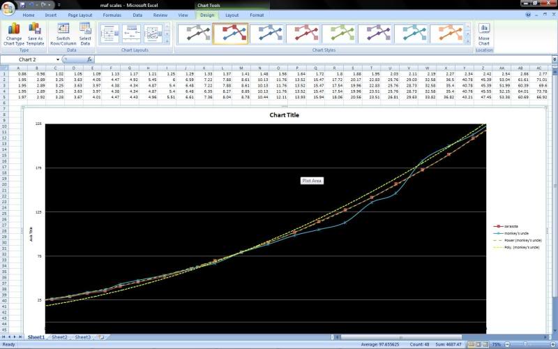
but at the same time, i've floated the idea elsewhere that possibly a power (or maybe polynomial) trend line of such a curvy line may be the right thing to do to smooth it out.
Here's a scale I made with baseline using a pretty small amount of data (with some junk data in there). THe red linear solid curve is the original scale. and the blue curvy one is the new scale. The two dashed linear curves are different trend lines, one polynomial and one power. Very interesting, I think
I would only worry if air flow in your scale decreases with load or if it's really rollercoaster-like. I think either of those would mean you need more data before scaling your maf.
but at the same time, i've floated the idea elsewhere that possibly a power (or maybe polynomial) trend line of such a curvy line may be the right thing to do to smooth it out.
Here's a scale I made with baseline using a pretty small amount of data (with some junk data in there). THe red linear solid curve is the original scale. and the blue curvy one is the new scale. The two dashed linear curves are different trend lines, one polynomial and one power. Very interesting, I think
U-Stink-But-I-♥-U
iTrader: (1)
Joined: Mar 2005
Posts: 2,004
Likes: 2
From: 12 o'clock on the Beltway.
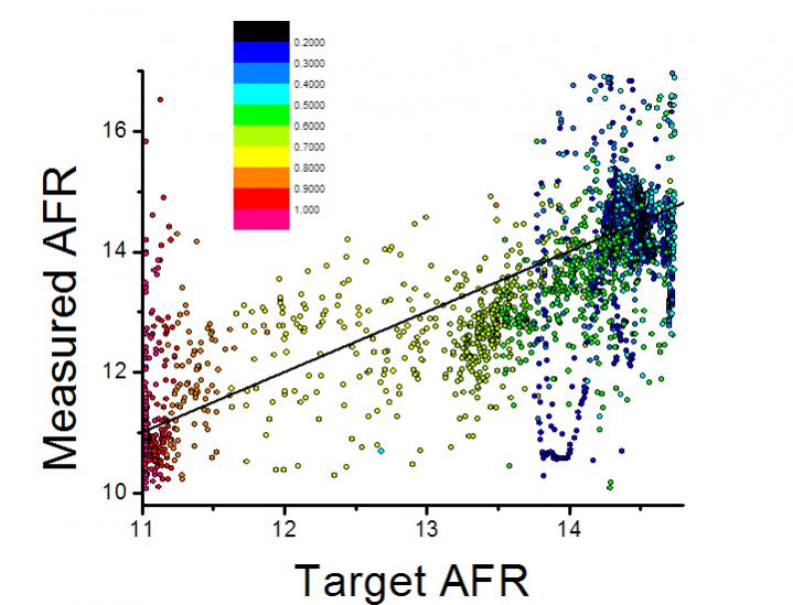
I am still hoping that someone will carefully look at my second graph. Is my rationale at least reasonable? I am holding off doing the experiment as I am hoping to see some potential variables that I am not taking into account. I want to highlight the fact that currently I have NO major issues with hitting my target AFRs. There are some things to clean up, but I think I am seeing data that is in the neighborhood of "good." (Average percent error is -1.48%; R=0.78)
Brettus, from a modeling perspective (I have spent a great deal of time in this area) you are absolutely right if you are speaking of a theoretical model. A description of the variation in volts in a heated wire subjected to a moving fluid (with it's own attendant parameters) has been essentially completed and validated experimentally. So if we had a "clean" system, we too should observe a smoothly varying MAF calibration curve. The fact that we have systematic deviations in the physical behavior that is not described by the model means that there is something different in our system than the "clean" system.
So, really, from that perspective, it makes complete sense that we are seeing a wavy MAF calibration. It means that there are problems somewhere. But I think that the objective should be to minimize the wavyness particularly if the wavyness is due to errors in fueling.
From what Kane is describing and from what I have read on his website, I think his approach is exactly this. And I think his insistance on LOTS of data is great, tho, I dont know if his analysis is correct as I am not sure if his stats take into consideration non-normal distributions. But I am sure it is quality.
Kane, What I mean about non-normal is that to use things like standard deviation, you assume that your data is normal. However, when I plot a histogram of the percent error of my measured AFRs from my target, I see a distinctly non normal population. What I see is a histogram with large "wings."
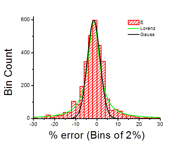
You can see that this histogram fits well to a lorenzian curve as opposed to a gaussian. Lorenz studied behavors that showed a great propencity for outliers, so much so that they could not really be called outliers but were inherent to the system. How this affects your analysis, I am not sure. In fact, as long as you are not seeing bimodal populations, I think running variance based analyses is fine, but maybe this should be thought through.
Brettus, as for your issue with being on one side of your target AFR in WOT and the other side at cruise, are you too rich in boost and too lean at cruise? Have you considered a small vac/boost leak?
As an aside, some folks insist that tuning is more art than science, I think that statements like this come from folks that aren't very scientific. I haven't experienced anything so far that is anything like art and dont expect to in the future.
Brettus, from a modeling perspective (I have spent a great deal of time in this area) you are absolutely right if you are speaking of a theoretical model. A description of the variation in volts in a heated wire subjected to a moving fluid (with it's own attendant parameters) has been essentially completed and validated experimentally. So if we had a "clean" system, we too should observe a smoothly varying MAF calibration curve. The fact that we have systematic deviations in the physical behavior that is not described by the model means that there is something different in our system than the "clean" system.
So, really, from that perspective, it makes complete sense that we are seeing a wavy MAF calibration. It means that there are problems somewhere. But I think that the objective should be to minimize the wavyness particularly if the wavyness is due to errors in fueling.
From what Kane is describing and from what I have read on his website, I think his approach is exactly this. And I think his insistance on LOTS of data is great, tho, I dont know if his analysis is correct as I am not sure if his stats take into consideration non-normal distributions. But I am sure it is quality.
Kane, What I mean about non-normal is that to use things like standard deviation, you assume that your data is normal. However, when I plot a histogram of the percent error of my measured AFRs from my target, I see a distinctly non normal population. What I see is a histogram with large "wings."
You can see that this histogram fits well to a lorenzian curve as opposed to a gaussian. Lorenz studied behavors that showed a great propencity for outliers, so much so that they could not really be called outliers but were inherent to the system. How this affects your analysis, I am not sure. In fact, as long as you are not seeing bimodal populations, I think running variance based analyses is fine, but maybe this should be thought through.
Brettus, as for your issue with being on one side of your target AFR in WOT and the other side at cruise, are you too rich in boost and too lean at cruise? Have you considered a small vac/boost leak?
As an aside, some folks insist that tuning is more art than science, I think that statements like this come from folks that aren't very scientific. I haven't experienced anything so far that is anything like art and dont expect to in the future.