DIY: Moto IHF1000 Bluetooth handsfree and Cellular Power Amplifier Install


Thread Starter
Registered
Joined: Oct 2005
Posts: 77
Likes: 0
DIY Updated 12-16-05: Moto IHF1000 Bluetooth handsfree & Cellular Power Amp Install
Motorola IHF1000/ IHF-1000/ 98676/ SYN1277A Bluetooth car kit Consumer Brochure links here:
http://www.motorola.com/automotive/p...c_consumer.pdf
Motorola IHF1000/ IHF-1000/ 98676/ SYN1277A Bluetooth car kit Technical specifications Brochure links here:
http://www.motorola.com/automotive/p..._technical.pdf
I swear I stole only the best ideas from the DIY forum! Thank you to all of you who helped me by blazing new trails before me.
One caveat before I start- I have a motorola v600 cell phone and the IHF1000 works great with it. Before buying it, I did a lot of reading and research and everyone that had a Moto phone had zero problems. There were a few people that had other than Moto phones that didn't have all features implemented... but that is not a failing of the IHF1000, that rather is a lack of options available on the other cellphones.
First of all... I like the IHF1000 a lot! It does everything I want and does it very well. If anything, I might want more storage for contacts... it only has 10. This doesn't sound like much, but for me it's working. You have a small panel (approx 2" x 1-1/4" with rounded corners) that is softly backlit... When you get in the car and turn on the ignition, after about 10 seconds a female voice says 'phone 1 connected'. Press the center button on the interface panel and she asks what you want to do. If you don't know, just say 'help' and she lists all commands for the menu you are currently in. If you have entered any contacts in the contact list, you can say 'dial Katy Smith'... the voice responds, 'Do you want to call Katy Smith?' ...say 'yes' and she responds 'dialing'. You hear the phone ringing and when the Katy answers, you start you conversation. At the end of the conversation, most times you hear her say 'disconnected'. Sometimes however, the phone at the distant end doesn't disconnect immediately, and in that case you can just press the hang-up button on the interface.
Or, if you press the center button, and when she asks what you want to do, you can say 'Dial number'. She asks 'Number please' and you recite the number '123 456 7890'. She responds 'Do you want to dial 123 456 7890?'. You respond 'Dial' and your number is dialed as before.
There is no training involved for the voice recognition. It is very accurate. The interface recognizes numerous languages which can be switched in one of the setup menus, so if you want to switch to french or italian, or one of any number of other languages you can. If you go to Motorolas website the manual can be found in PDF format and downloaded.
I am extremely satisfied with this product. The installation is quite easy, depending on where you want to mount it... the interface box is small and light enough that you could mount it with tie wraps under the dash behind the glove box. I opted to remove the center console and mount it at the very back under the rear passengers' storage compartment as far back as you can. It barely fits here, but it does fit nicely. I used tie wraps to mount it, but you could use double sided foam tape to mount it. I recommend you test fit it and put the center console back on to make sure you're not hitting the bottom of the storage compartment- it's close but it does fit- before you finalize your mounting and dress the cables. I opted for using the motorola speaker instead of the stereo speakers for two reasons. First, the moto speaker works just fine and is small... I mounted it up under the passenger compartment dash to the left of the glove box- theres a big wire bundle up there I just tie-wrapped it to and it is out of the way and points downward, toward the floor. This is the third handsfree interface I have installed in one of my vehicles, and it is very important for good speech recognition and echo cancellation that the speaker and microphone not be pointing at each other. That is the second reason I opted not to try to connect to the car stereo. The microphone is mounted on my sunglasses holder (overhead console) all the way on the left side and angled towards the front of my head. It works quite well here... I may make a little bracket that will mount it just to the left of the overhead console when I get a chance, but for now where I have it works well and doesn't interfere with the operation of the sunglass holder.
As for the interface panel... well for me, that was the most work of all. Because I have a cassette in my stereo, after a lot of deliberation I decided the best place to mount this was in the center of the air conditioning louvre above the stereo. I had to remove the stereo, take the vent assembly out, construct a small bracket that is tie-wrapped to the center post of the louvre assembly. To do this, I had to seperate the louvre from the vent (several screws) and remove a small piece of plastic from the back of the center post of the louvre. Then re-assemble the louvre to the vent, run the control cable through the bottom-most slit in the louvre assembly (it doesn't interfere with the louvre operation at all and ends up being behind the interface panel for the handsfree adapter so you can't even see it). Then reinstall the louvre-vent assembly and stereo in the center console. That's the hard way, but it looks pretty close to factory.
IF you don't have a cassette or mini-disc player in your stereo, the next best (and much easier) place to mount would be in the blank panel under the stereo (where a lot of people have mounted their remote displays for radar detectors). MUCH easier to do (although you'll still have to take out the stereo).
For power, you need BATT (always on) and ACC (on when the ignition is on). I currently use power from a cable harness I installed and tie-wrapped to the factory harness above the steering wheel. I runs from the fuse box in the drivers side door jam where power is tapped off using Littlefuse Add a Circuits, and runs to the center console behind the ashtray. This is where most of the connections to the handsfree adapter are made.
After doing a lot of research I found that there is a mute connection on the factory stereo, but no wire in the harness for it. Incidentally, the IFH1000 signal to mute is a 'wired-OR' open collector connection... what this means is that it is possible to connect multiple control signals to the mute input... in my case, i plan to connect the IHF1000, a Blinder LASER jammer and will try to interface my Valentine V1 LASER/RADAR detector to mute the radio when they go off. that should wake me up in a hurry and get my foot off the gas and on the brake!
After more research I found that there are connectors (male and female) with about 6" of wire attached that can be purchased from a two companies that make them for adapting aftermarket stereos to various cars. I special-ordered these and when I received them I built a short harness with them that plugs in place between the stereo and the factory harness. My adapter harness will allow me to connect the mute wire to the stereo, and to tap off the BATT and ACC lines from the factory harness to power the handsfree adapter (I don't really need to do this, but as long as I'm connecting the mute wire, the extra power connections are easy implement). This will cost about $70 for all the parts... I could have bought one connector for a lot cheaper and just taken one contact out of it and installed it in the factory harness, but my car is still under warranty, and I want to keep the option to restore everything to factory condition if I ever need warranty work to be done on the stereo. Also,I wanted to get access to two signals that are used for dimming the instrument panel lighting so I could use them to dim the indicators on some of my add-ons.
The J-01 connectors (the large connector on the back of the stereo):
Scosche Connectors:
www.scosche.com (there is another scosche website which has been abandoned and has very old info on it.... it is the one most often turned up when doing a search for 'scosche' so make sure you don't go to the wrong one!)
sales@scosche.com
Sales: (800)363-4490 ext.1
techsupport@scosche.com
Tech Support: (800)363-4490 ext.3
The connector that plugs into the car harness used to be p/n MA03, now re-named MA03B
The connector that plugs into the head unit used to be p/n MA03R, now re-named MA03RB
I have ordered these connectors from a local distributor and called back repeatedly and never been able to get one of the connectors, basically because the guy is a jackass and keeps saying he ordered them, but never has.
The manager at a local Circuit City said he could get these in a few days special order, but my Metra connectors had already arrived by the time I found this out.
Metra
www.metraonline.com
Sales/Manufacturing:
460 Walker St.
Holly Hill, FL 32117-2699
(800)221-0932
(386)257-1186
R & D / Marketing
3201 East 59th St.
Long Beach, CA 90805-4501
(800)944-6235
(562)634-9910
(562)634-9920
The connector that plugs into the car harness is a Turbowire 70-7903 - I paid $7.29 for these.
The connector that plugs into the head unit is a Turbowire 71-7903 - I paid $10.85 for these.
These are supposed to be available (special order, of course) from Best Buy and Circuit City according to Metra sales.
I got the name of the local distributor from Metra in Holly Hill. I ordered several of each gender so I enough pins to make a jumper harness between my head unit and Bose factory stereo, and tapped off BATT, ACC, and GRND from the harness for my Moto IHF1000 bluetooth handsfree adapter. I also added a pin for the MUTE function (pin L) going to the head unit (pin L). In addition I tapped off the PULSED DIMMER TNS+ and and INVERTED DIMMING signals to get some of the lighting for my add-ons to follow the instrument panel dimming.
BTW, 'PULSED DIMMER TNS+' (pin e) is somewhat of a misnomer as it is not pulsed at all. It is a line that switches to +12v when the light switch is either in PARK or HEADLIGHT position. When lights are switched off it is at 0V. It provides a +12v signal to indicate that some exterior lighting is on.
'INVERTED DIMMING' (pin g) is 0V when the panel dimmer is in the detent position. When it is switched out of detent and advanced a bit, a narrow 12v pulse starts at a period of approximately 5mSec (minimum dimming), and as the dimmer is advanced, the pulse gets wider until it is at 12v for 4.2mSec and at 0v for 0.8mSec out of the 5mSec for maximum dimming. This signal provides a varying pulsewidth Ov signal to the negative side of the panel lights.
Almost all of the info I initially got was from Stephen Fosketts' Miata website (many thanks Stephen, you saved me many hours of reverse-engineering time!!!), where J-01 has a pinout for a 2004 RX8 which is accurate for my 2005 model also, with the exception of some wires not in the harness because I don't have the navigation unit i.e. NAV: PARKING BRAKE pin k, NAV: REVERSE pin m, and a black/white wire at pin t. Strangely, there is a wire at pin h POWER ANT. This wire presumably signals when the radio is turned on, and could probably be used as a trigger to turn on an aftermarket amplifier.
Where I bought the IHF1000... I bought it from a company called CompUPlus (www.compuplus.com). I paid $195.95 plus 14.95 shipping... I found it for about $10 - $15 less elsewhere, but from small companies I've never heard of... I've done business with CompUPlus for years, and knew if there was any problem with the transaction, I'd get my money back.
After installing the IHF1000 I finished up the testing and installation of a bi-directional cellular amplifier and external antenna for better coverage in those fringe areas. That's another saga. In the process of testing, I've had to start learning how to hack my cell phone software to re-enable some features that ATT disabled in my Motorola V600. In particular, the engineering menu that lets you read the power that the cell site is putting out to your phone, so that I can quantitatively evaluate the effectiveness of the cell phone amp. If anyone out there has some background in this, please pm me, I could use a little help.
I drilled no holes anywhere for this install... i spent a lot of time figuring out how to avoid doing this... I consider my car somewhat of a work of art, and it would be like driving a nail through the MonaLisa to hang it on the wall... if I ever want to remove everything, I can do it without leaving any trace whatsoever that it was ever there.
Last edited by Shinka in MD; Dec 28, 2005 at 02:15 PM.
Thread Starter
Registered
Joined: Oct 2005
Posts: 77
Likes: 0
This adapter harness was built to go between the head unit and the factory harness so that I didn't have to cut any wires. I tapped off BATT, ACC, GROUND, and added a MUTE contact. I also tapped off the instrument panel dimmer signals to use for the lighting in my add-ons.
This thread has more info on the connectors and sources for them, as well as links to the connector pinouts:
https://www.rx8club.com/series-i-interior-audio-electronics-24/speaker-sizes-harnesses-kits-etc-audio-install-reference-74664/
I had problems with the Metra connectors I bought; actually just the type that plugs into the back of the stereo. I looked them over very carefully when I first got them and found that a number of contacts were not fully seated in the connector. I spoke to Metra tech support several times regarding this and there response was that they've had no complaints from any other customers... I bought the connectors at two different times so I must be really lucky to get the only two bad ones ever made. I finally gave a tug on the wires that were not fully seated and they came right out of the back of the connector body! Looking closely at them it appeared that the prongs that crimp around the insulated part of the wire were not fully crimped... I used some flat bladed pliers to carefully crimp them into a round shape around the insulation and when I reinserted them they locked into place! If I hadn't discovered this little problem ahead of time, I might have had intermittent problems and had to pull the stereo back out again to find out where the problem was... not something I would want to do. I don't know if the Scosche connectors are any better, I ordered some over two months ago and never got them. I keep calling the dealer (a stereo installation shop) and they keep telling me they'll call Scosche, but I don't think I'll ever see them.
If you just want to wire your power connections to the fusebox instead of tapping them off from the radio harness, you really don't need to build this harness at all. Just use a couple of Littlefuse MINI Add-A-Circuit adapters P/N FHM200BP (www.littlefuse.com)... I bought mine at a local Pep Boys, but many automotive supply stores have them in the electrical section. I used the CIGAR 15A location for ACC power (the ACC 7.5A location could also be used)- both of these fuse locations provide power when the ignition key is in the ACC or RUN position. I used the AUDIO 20A fuse location for the BATT power- this is on even when the key is not in the ignition. I also used the A/C 7.5A location for a second ACC fused line (this fuse is on only when the ignition switch is in the RUN postion, but since I used it for power to my Valentine V1 and Blinder Extreme that's just fine, because you really don't need those powered up unless the engine is running), and that is why I used the CIGAR 15A location instead of the ACC 7.5A location which would have physically interfered with me using the A/C fuse location. It's much clearer to see what I mean when you actually look at the fusebox. This is how I powered my IHF1000 before I built my harness... now these power feeds are used to power my Wilson Cellular amplifier and a Cell phone charger that is buried behind the ashtray with only the wire run to the hangup cup to charge my cell phone when it's in the hangup cup.
The easy way to get MUTE functionality:
If you want the mute function only, you could buy one connector that plugs into the back of the stereo. Then CARFULLY cut the connector apart and harvest one of the small contacts (it's actually a female contact and there are three sizes... the one you want is the smallest size). Solder a piece of wire to it and insulate the connection with shrink tubing. Insert the contact into the back of the large connector in the harness that goes to the stereo. The pin will fit only one way... it has a little notch in it that locks in in place... you will see what I mean when you cut the connector apart to harvest the contact. There is an L shaped slot on one side of the hole in the body of the connector (it's for inserting a contact removal tool)... the notch in the contact is aligned with the wide part of that L shaped slot. It's hard to describe so I'll try to put a picture or two this in the DIY. The hole the MUTE contact is inserted into is position "L"... see here:
http://stephen.fosketts.net/miata/audiopins/index.html
...about 3/4 of the way down the page you will find "2001 models- J-01"... this shows how all the pins are oriented, and the column labeled "2004 RX-8" matches up with the harness in my Shinka (no navigation in the Shinkas). Once you've installed the contact, reassemble the stereo in the center console and connect the other end of the wire to the yellow mute wire coming from the IHF1000. Now you are done. When your phone rings, the stereo will mute, and unmute when the call is complete. When hit the big blue button on the IHF1000 controller the stereo will mute and stay muted until you finish whatever you are doing. You can pick up your power from the fusebox and put the speaker and mic where ever you like and you're done!
That second option is a lot easier and cheeper than what I did, but I had some special needs from this harness to use in other projects, and since my 8 is still under warranty, I didn't want to do anything that couldn't be undone if I needed some warranty repair work.
A few tips... removing the stereo:
REMOVE THE GLOVE BOX FIRST! It's really easy, and once you've done it, it makes getting the stereo out so much easier. Open the glove box. Pop off the plastic arm that attaches to the dash-pot (the thing that makes the glove box glide out when you open it) on the right side of the glove box. Squeeze the two sides of the glove box until the two prongs (left and right) that keep it from opening too far clear the edges of the opening. Now you can pop the glove box off it's hinges and store it somewhere until you're finished.
With the glove box out of the way, and the shifter surround removed, place a couple of towels or soft cloths over the end of the shifter where you removed the ****... it screws off on the 6 speed, leaving sharp threads you want to cover up so you don't scratch the other pieces as you remove them. Next remove the two screws that hold the ashtray and pull it out of the console... there are two more clips that hold it, just pull it straight out. Next remove the two screws in the bottom of the stereo bezel- they're a little hard to see because they're behind where the ashtray used to be (by the way, don't let the ashtray or shifter bezel remain attached to the wiring harness... pop the connectors off and get them out of the way to avoid scratching the center console. The hardest thing to get off is that ashtray bulb. You have to squeeze the two flat sides of that bulb holder where it goes through the hole in ashtray assemble... its a bit tricky to do... take your time and think it through and I'm certain you'll get it out.)
Okay, I've heard many people say the way to remove the stereo is to put some tape around a screwdriver and pry the sides of the stereo bezel until the clips pop out. I have taken my stereo out several times now, and after reading about people who broke their bezels in the process or scratched up the sides of the console in the process, I think I have a better method. FIRST... remove the 10mm bolt that goes throught the side of the stereo... you have to pop off the plastic panel under the steering wheel (the top edge has two snaps that pop loose the panel swivels down and pulls out) underneath there is a metal plate- remove the four phillips head screws that hold the metal plate and set it aside... now the hardest part is getting that damn bolt out... it's gold colored from what I've read elsewhere... I don't know for sure because when the dealer added the cassette player to my stereo they never put the bolt back in! It really should be in there. Once you locate it, from what others have said, put some plumbers putty in the end of the socket so it doesn't fall into the center console when you remove it... and be very careful once it's loose. Once that is done, move to the passenger side... now you get to find out why I had you remove the glove box. Stick your right hand through the hole on the left side of the glove box and find the back of the stereo. Once your hand is back there, gently grasp the bottom of the stereo front bezel and apply GENTLE GENTLE pressure to pull it out from the console... be careful though, and remember it's just made out of plastic! AT THE SAME TIME push on the back of the stereo, push on one side, then the other just enough to pop those clips loose. Mine came loose in two gentle pushes and your left hand on the front is mainly just to guide the stereo and keep it from flying out of the stack when the clips pop loose. STOP THERE! Don't attempt to take the stereo out yet!
When the bezel has cleared the console by about an inch, run some tape up the sides of the center console so you don't scratch it up in the process of unlatching the connectors on the back of the stereo. If you skip this step, you will most certainly scratch up your nice car!!!
Use several layers of tape and get it around the edges. This will be the last thing you remove once you are finished working in here.
There are two connectors at the bottom of the bezel to remove for the fan and 4-way flasher control. All the connectors have locking tabs except the antenna connector... it just snaps out of and into it's connection... kind of like an earphone jack but with a bit more force. I didn't know how this damned thing came loose the first time I tried to remove it and was afraid I would break it, but it turned out I just needed to use a little more force than I expected. It's not like the Motorola- style antenna connectors on American cars, it has a little ball on the end of the center conductor that locks it in place. There are two or three connectors on the back of the stereo itself depending on if you have a model with a Sirius sat receiver. They all have locking tabs that are hard to find, there isn't much slack in the cables and you may have to feel your way through the process by reaching through hole in the side of the glove box area. The largest connector has it's latch on the bottom... I don't remember the orientation for the others. Theres another connector covered in foam plastic, but it doesn't need to be removed... it just goes from one place on the stereo to another place on the stereo and stays in place when you remove the stereo. Take your time. Try not to wiggle the stereo from side to side any more than you have to... the back of the stereo has plenty of screws, sharp corners, and other traps just waiting to scratch up your center console. When you finally get all the connectors off, carefully pull the stereo out and store it somewhere safe. That's all there is to it. Go have a drink and get some band aids, because by now you probably have a few cuts from unseen sharp edges in the center console. The drink is strictly for antiseptic purposes... I've heard it's more effective to drink your alcohol than to apply it topically.
That was simple, right?
Another tip... always have 10 times more time than you thought it would take available to do the job. And take your time.
Last edited by Shinka in MD; Jan 6, 2006 at 01:57 PM.
Thread Starter
Registered
Joined: Oct 2005
Posts: 77
Likes: 0
The first photo shows how I labeled the fuse holders... If I blow a fuse I don't want to depend on my memory to figure out which fuse goes where...
The second photo shows the connector from the Valentine-V1 / Blinder on-off switch at the top and the power indicator dimming circuit interface board at the bottom. It was covered with clear shrinkable tubing after adjustment to insulate it from contact with anything and tucked behind the dress panel at the left side of the drivers' foot well.
The second photo shows the connector from the Valentine-V1 / Blinder on-off switch at the top and the power indicator dimming circuit interface board at the bottom. It was covered with clear shrinkable tubing after adjustment to insulate it from contact with anything and tucked behind the dress panel at the left side of the drivers' foot well.
Last edited by Shinka in MD; Dec 16, 2005 at 01:49 PM.
Thread Starter
Registered
Joined: Oct 2005
Posts: 77
Likes: 0
In the center of this photo you can see where I mounted the hard-wired power supply for the Valentine V-1. It is connected to the A/C fuse thru the on/off switch and to ground. The modular telephone cables connect the power supply to the Valentine V-1 and remote Concealed Display (Item 20110).
It is "mounted" with one side of a piece of super-velcro that is stuck to the power supply and the carpet serves as the other 'side' of the velcro...
It is "mounted" with one side of a piece of super-velcro that is stuck to the power supply and the carpet serves as the other 'side' of the velcro...
Last edited by Shinka in MD; Dec 16, 2005 at 02:14 PM.
Thread Starter
Registered
Joined: Oct 2005
Posts: 77
Likes: 0
The Motorola IHF1000 is a Bluetooth Handsfree adapter. If you drive a 6m and use a cellphone, something like this is a must-have.
Before installing, I wired up everything on the kitchen table and made sure it worked... I didn't want to find out that it was broken out of the box after I had disassembled my 8 and installed everything.
The location I chose is under the center console, all the way in back by the trunk pass thru. I have a Shinka, ergo no nav package, so this might not work out for you if you have one...
I wire-tied the IHF1000 using existing holes... it just barely fits under the rear passenger storage compartment... but it fits!
Last edited by Shinka in MD; Dec 16, 2005 at 01:55 PM.
Thread Starter
Registered
Joined: Oct 2005
Posts: 77
Likes: 0
These photos show how the cables were routed thru the center console... I kept everything wire tied to the factory housing and away from metal things that heat up...
Last edited by Shinka in MD; Dec 16, 2005 at 02:05 PM.
Thread Starter
Registered
Joined: Oct 2005
Posts: 77
Likes: 0
Now that the cabling is done, here are the connectors on a harness I added that bring extra BATT and ACC from the driver's side fuse box... the harness is run from the fusebox and over the steering column and is enclosed in cable loom to protect it from any sharp metal edges... those of you who have already been working under the dash in your 8s know what I mean, and I bleed for you... literally.
Thread Starter
Registered
Joined: Oct 2005
Posts: 77
Likes: 0
Since I have a cassette player, I didn't have some of the options that others had for mounting the control panel. I temporarily mounted it in a few places, but none were operationally satisfactory... either they were inconvenient to reach, or they were in the way and I was bumping into the controls accidentally. I decided one of the last pieces of available real estate was in the middle vent. I constructed a mounting bracket out of a plastic cable clip and used a wire tie to attach it to the middle of the vent. To do so, I had to pull the head unit and the vent unit, but I had to pull the head unit anyways to install my harness adapter. After staring at the vent for a while, I completely disassembled it (paying very close attention to where all the parts came from!) and was able to attach the bracket with one wire tie... I did have to cut away a bit of plastic from the back side of the vent, but it's impossible to see without taking the whole thing apart. I routed the wire through one of the lower vent louvers, and it's not noticeable and doesn't interfere with the operation of the louvers themselves. The control panel uses double-sided sticky tape to attach to the mounting surface... and no, running the heater has not affected the integrity of the tape at all.
For those of you who have other mounting options, I highly recommend that you use them... this location worked out great for me, but it was a total pain in the *** figuring out how to make it work. And putting the vent back together with all the louver parts trying to fall out was an exercise in patience for me...
For those of you who have other mounting options, I highly recommend that you use them... this location worked out great for me, but it was a total pain in the *** figuring out how to make it work. And putting the vent back together with all the louver parts trying to fall out was an exercise in patience for me...
Thread Starter
Registered
Joined: Oct 2005
Posts: 77
Likes: 0
a different angle of the bracket so you can see that the part that attaches to the vent was cut down in width to match the center vertical post to which it is attached... the narrow bit where the wire tie attaches it to the post was carefully sized to fit tightly in the vent groove so when the wire tie is pulled tight, it can't twist... it's pretty rigid if installed properly.
Last edited by Shinka in MD; Nov 22, 2005 at 03:06 PM.
Thread Starter
Registered
Joined: Oct 2005
Posts: 77
Likes: 0
This is the controller, once mounted... the biggest modification i made was on the back side of the louvre... there was a plastic post that a screw from the vent system screwed into to hold the two pieces together (along with 2 other screws on the sides of the assembly). On the four sides of the post there are 4 lateral projections to help strengthen the post... I had to trim one of the four projections to accomodate the tie-wrap I used to hold the bracket I built for mounting the control panel in the center of the vent... that was the only modification I made to the car.
Last edited by Shinka in MD; Nov 23, 2005 at 10:07 AM.
Thread Starter
Registered
Joined: Oct 2005
Posts: 77
Likes: 0
I mounted the handsfree microphone to the rear-left corner of the sunglass holder after experimenting to make sure that it wouldn't interfere with the holder's operation. This has been a good location in other vehicles I've owned and is unobstructed, doesn't pick up wind or windshield wiper noise. I had thought about mounting it on top of the steering column shroud, off to the right a bit so it didn't obstruct my view of the tachometer bottom scale, but I decided against it for now because it I were talking while making a turn, the steering wheel spokes would periodically be blocking the microphone. If anyone comes up with a better location, please let me know...
...also in the pic is my Valentine 1...
...also in the pic is my Valentine 1...
Thread Starter
Registered
Joined: Oct 2005
Posts: 77
Likes: 0
...since I showed you my radar detector, here is the remote power switch... it switched the power for both my Valentine 1 and for my Blinder Extreme, as yet still in the installation phase...
The switch is a C & K (now ITT Industries) part no. 7201J51ZQE22... it is a DPDT (double pole double throw- which means it has two seperate circuits that can be switched on in either position of the switch). It can be purchased from Allied Electronics (www.alliedelectronics.com) as their p/n 676-0175 for $8.17 each, plus shipping... you can order off the web or call up and place your order by phone. The LED is a Radio Shack p/n 276-316 blue 5mm LED with an output of 2600 mcd. If you prefer red, they also sell p/n 276-307 which has an output of 3000 mcd. That means their both pretty bright. I will eventually replace the single LED with two, one a power indicator and the other, my Blinder Extreme LASER indicator.
**I've replaced the LEDs with orange-red ones that closely match the instrument panel nite lighting scheme:
Agilent HLMP-EH31-SV0000 (DigiKey P/N 516-1373-ND)
It is a 623 nm (red/orange) 1300 mcd LED with a Vf=2.08v and 30 degree viewing angle.
One note... try to find the type of mounting clips for the LEDs that have a thru-hole bezel on the front, and a round locking ring on the back (second photo, left hand side)... if you use just the kind that has only the thru-hole bezel without the locking ring, the LED can be easily push back through the mounting hole, and you WILL do this when you accidentally push on it instead of the switch. With the locking ring in place on the back side, this is virtually impossible.
A second type of LED mounting clip is shown on the right side of the second photo and the third photo... this is available from Radio Shack (Catalog #: 276-079). It works pretty well also.
Last edited by Shinka in MD; Dec 16, 2005 at 02:40 PM.
Thread Starter
Registered
Joined: Oct 2005
Posts: 77
Likes: 0
...I also installed a Wilson Electronics p/n 812201 cellular power booster and Wilson Electronics p/n 301103 magnetic mount external antenna (www.wilsonelectronics.com... the amplifier was recently release and wasn't on the website the last time I checked... I bought everything from WPS Antenna www.wpsantenna.com - Wilson and WPS (special thanks to Matt Larson at WPS for all the help and support he provided me with during the testing phase of this project!) both treated me great and helped me a lot with the pre-installation planning)... I mounted the amplifier under the deck in the pass-thru, and once again I was lucky to find some existing holes that I could fish some wire ties thru to secure the amp. The coax between the phone and the amp runs down the center console along with the IHF1000 cabling.
It amplifies the 824-894 MHz and the 1850-1990MHz bands, boosting the signal in both directions as needed (the cell phone and cellphone tower communicate with each other to determine how much power is needed for each to transmit an acceptable signal, and adjust their power outputs accordingly... this is a function of the cellphone and tower, not the amplifier... the amplifier just provides more gain when needed).
The 812201 amplifier is a Direct Connect Cellular/PCS,GSM/TDMA amplifier and doesn't support CDMA (Compatible with GSM/TDMA Cellular/PCS Carriers and technology only, for example: Cingular, T-Mobile. It is NOT COMPATIBLE WITH CDMA, FOR EXAMPLE: VERIZON, SPRINT, ALLTEL, US CELLULAR, MIDWEST WIRELESS OR IDEN: NEXTEL, SOUTHERN LINC)... but they do make another which is slightly more expensive that supports everyone- the model number for this one is p/n 811201 and is compatible with all Cellular/PCS Carriers and technology (GSM, GPRS, EDGE, CDMA, EVDO, EV-DO, TDMA, AMPS/Analog) except iDEN (Nextel, Southern LINC, Mike). I opted for the 812201 because it's $50 cheaper, and mainly because the rules for power are different for GSM, so there's slightly more power output when the conditions warrent it... this amplifer works great, and definitely increases the distance I can communicate from a cell site when coupled with the external antenna which has gain.
They are both direct-connect amplifiers, so your phone must have an antenna connector... I also tested a Wilson wireless repeater... no direct connection to the cell phone. It uses a pickup antenna inside the car to connect to your cell phone and an external antenna to re-radiate the signal to the cellphone tower.... don't bother wasting your time or money... these things just don't hold a candle to the direct-connect models.
The Wilson 301103 mag mount antenna provides gains of 5.12 dBi in the 806 - 894 MHz band and 6.12 dBi in the 1850 - 1990 MHz band.
Last edited by Shinka in MD; Nov 23, 2005 at 12:22 PM.
Thread Starter
Registered
Joined: Oct 2005
Posts: 77
Likes: 0
...this is how the antenna cable is routed... it comes from the antenna and is inserted under the trunk seal, and run to the bottom where it emerges as a drip loop... it then runs back up to one of the holes for the right rear combination light and inside the trunk. The combination light has a seal on the back of it that keeps everything water tight. I stole this idea from the Mazda Sirius Sat radio installation which mirrors the same thing on the left combination light... if it's good enough for the Mazda engineers, it's good enough for me.
Thread Starter
Registered
Joined: Oct 2005
Posts: 77
Likes: 0
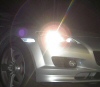
...outside, the antenna is mounted on the rear quarter panel close to the trunk opening. It doesn't interfere at all with the trunk opening and closing...
...there's enough slack in the cable so you can detach the antenna and stow it in the trunk if desired...
...there's enough slack in the cable so you can detach the antenna and stow it in the trunk if desired...
Last edited by Shinka in MD; Nov 23, 2005 at 12:04 PM.
Thread Starter
Registered
Joined: Oct 2005
Posts: 77
Likes: 0
...the center console, re-assembled. Everything is nice and neat, and look! No cigar lighter adapters in the ashtray!
...notice how the time on the head unit and time on my phone don't match- I took this pic as soon as I reassembled the interior, before I remembered to reset the clock...
The phone is connected to the cellular antenna with a Motorola hangup cup. This cup was used for the non-Bluetooth handsfree units, but I bought it so that I can just put the phone in the hangup cup and it automatically makes the connection to the amplifier... also, there is a phone charger buried behind the ashtray and connected to one of those spare ACC connectors I showed you earlier... it plugs into the back of the hangup cup and charges the phone when it's in the hangup cup. I added a switch to the hangup cup that senses when the phone is there and turns the cellular amplifier on and off.
The hangup cup is mounted using a Proclip... I'm very happy with it.
The remote display for my Valentine V1 is mounted in the ashtray. It is held in place with double-sided Super Velcro. The ashtray insert was removed to accomadate it. When the insert was removed, the red lense for the night illumination was removed also, as it is part of the insert. I had some thin red frosted plexiglass that is used for lenses on LED alphanumeric displays, so I cut a piece to size and used contact cement to glue it in place. If I can find a red LED replacement bulb for the one in the ashtray, I'll probably put it in and remove the red lens... I like to keep things as close to stock as possible.
Building a pass through harness was a lot of work, but like I said before, I'm happy I did it. My IHF1000 now borrows power from the stereo harness and the mute line is connected to the pass-through harness, so I have achieved what I originally set out to do... I have avoided having to cut or tap into the harness anywhere, and have made it possible to restore my 8 to factory condition if I ever need any warranty work done. A side benefit is that the large connector on the back of the stereo is a lot easier to get out because my pass-through harness adds about 6 inches to the length of that factory harness. There are still a few other connectors that are tight, but that one by far was the shortest in the harness. There's plenty of room to route the extra cable between the glove box and the stereo stack.
No holes were drilled in the 8 during the course of this project.
Well, that's it for now, I'll add more info and links to threads that tell how to disassemble various parts of the 8 as time permits... If I left anything out or am unclear about anything, please let me know and I will edit the thread...
Last edited by Shinka in MD; Nov 23, 2005 at 12:24 PM.