
DIY: IAT sensor for turbo


Thread Starter
Boosted Kiwi
iTrader: (2)
Joined: Apr 2006
Posts: 20,856
Likes: 1,807
From: Y-cat-o NZ
DIY: IAT sensor for turbo
I did this modification after pestering Mazda Maniac for details on what he did . So props to MM for coming up with this setup . Hopefully he will jump in and clarify anything that may be a little sketchy.
OK
* First get hold of your sensor from a wrecker. The sensor comes from the KL series motors
Quoting MM here "Its a family of V6 motors that Mazda put in several cars in the 90's.In its 2.5 liter form, it was in the MX-6, 626, 929, Millennia and the Ford Probe.
It was also available as a 1.8 liter (the world's smallest production V6) in the MX-3."
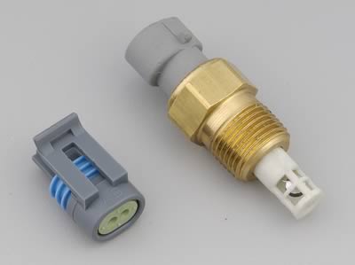
*Make sure you get hold of the plug that plugs into this along with about 400mm of wire attached.
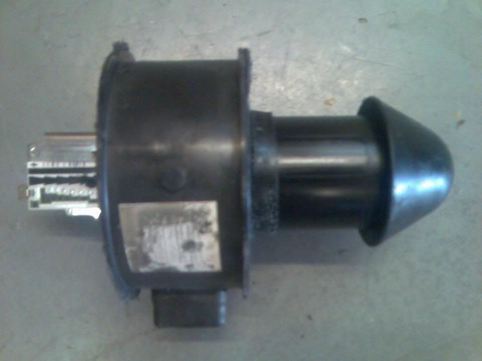
*Now you have to cut the sensor out of the housing along the red line shown .I actually went out a bit farther than the line to make more of a flange. Take care not to cut the end of the temp sensor off when you do this (I almost did) A hacksaw is the best tool to do this with.
This is what it looks like to start with :
OK
* First get hold of your sensor from a wrecker. The sensor comes from the KL series motors
Quoting MM here "Its a family of V6 motors that Mazda put in several cars in the 90's.In its 2.5 liter form, it was in the MX-6, 626, 929, Millennia and the Ford Probe.
It was also available as a 1.8 liter (the world's smallest production V6) in the MX-3."
*Make sure you get hold of the plug that plugs into this along with about 400mm of wire attached.
*Now you have to cut the sensor out of the housing along the red line shown .I actually went out a bit farther than the line to make more of a flange. Take care not to cut the end of the temp sensor off when you do this (I almost did) A hacksaw is the best tool to do this with.
This is what it looks like to start with :
Last edited by Brettus; Jan 17, 2009 at 10:43 PM.
Thread Starter
Boosted Kiwi
iTrader: (2)
Joined: Apr 2006
Posts: 20,856
Likes: 1,807
From: Y-cat-o NZ
*Now initially you will get something shaped like this :
Please resist the temptation to use this for other activities
*You need to cut around the sensor till you end up with a flange around it like this :
Please resist the temptation to use this for other activities
*You need to cut around the sensor till you end up with a flange around it like this :
Last edited by Brettus; Jan 18, 2009 at 12:30 PM.
Thread Starter
Boosted Kiwi
iTrader: (2)
Joined: Apr 2006
Posts: 20,856
Likes: 1,807
From: Y-cat-o NZ
*remove all the insulation tape from the maf wires right back to the loom .
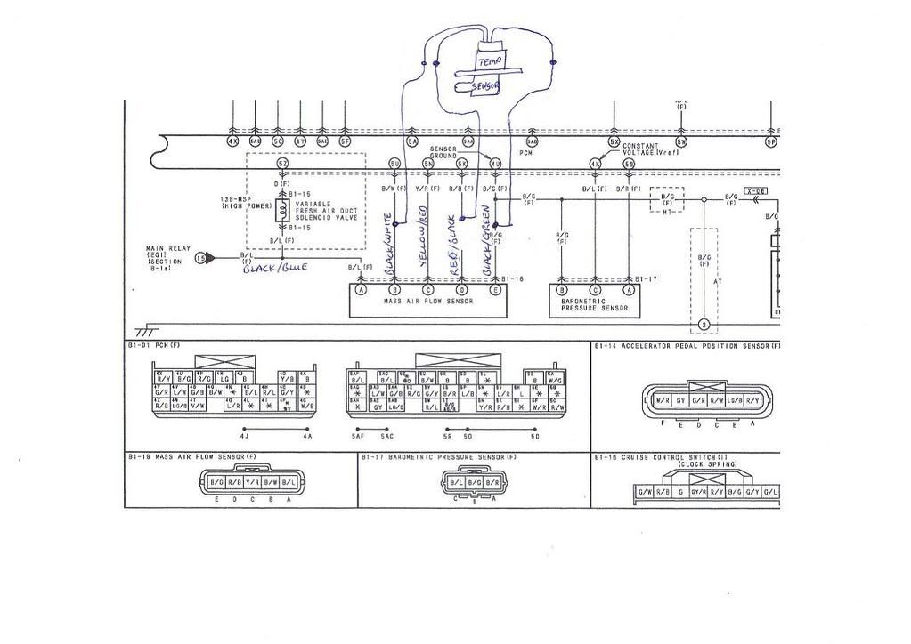
*Cut the red wire about 1/2 way along and join it to the wire at the front of the temp. sensor
*Splice into the other wires in the same position as shown below .... use a soldering iron to ensure a good join.
*once you know it all works , wrap insulation tape around both lots of wires
*Cut the red wire about 1/2 way along and join it to the wire at the front of the temp. sensor
*Splice into the other wires in the same position as shown below .... use a soldering iron to ensure a good join.
*once you know it all works , wrap insulation tape around both lots of wires
Last edited by Brettus; Jan 18, 2009 at 12:31 PM.
Thread Starter
Boosted Kiwi
iTrader: (2)
Joined: Apr 2006
Posts: 20,856
Likes: 1,807
From: Y-cat-o NZ
*Remove the intake pipe before the throttle body.
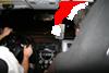
*now you need to cut a hole in your intake pipe the same shape as what is under the flange . I put mine very close to the coupling and used the coupling to hold the flange down at one end .
*at the other end i used a self tapping screw to secure the flage to the pipe . A bit mickey mouse I know - there will be a better way .....
*Put some gasket goo of some sort under the flange and mount it on the intake.
Last edited by Brettus; Jan 17, 2009 at 10:45 PM.
Thread Starter
Boosted Kiwi
iTrader: (2)
Joined: Apr 2006
Posts: 20,856
Likes: 1,807
From: Y-cat-o NZ
At cruise I see temps 10-12 degrees above ambient . When I go into boost it stays fairly steady going up a coulpe of degrees under prolonged boost @9-10psi .
What really does raise temps is sitting around at idle or heat soak after you turn off for a few mins . Have seen 25deg C above ambient in those conditions. Any kind of hard driving at low speed is bad as well .
before I relocated the sensor I was seeing way lower temps - stands to reason .
What really does raise temps is sitting around at idle or heat soak after you turn off for a few mins . Have seen 25deg C above ambient in those conditions. Any kind of hard driving at low speed is bad as well .
before I relocated the sensor I was seeing way lower temps - stands to reason .
Last edited by Brettus; Jan 19, 2009 at 12:00 PM.


Thread Starter
Boosted Kiwi
iTrader: (2)
Joined: Apr 2006
Posts: 20,856
Likes: 1,807
From: Y-cat-o NZ

Good to know. Since it is a 2 wire connection is it simply tapping into the MAF sensor wiring for the IAT ground (Black/Green) and cutting/joining the IAT sensor wire (Red/Black) to the new sensor? Not to mention having to rescale the IAT calibration in the tune.

lol. still 11 Deadly Questions since it can go in the #10 'Other Relevant Mods' Section.
Considering how many people actually do this mod using this Ford one, I see more people doing this IAT mod given the ease of picking up the GM sensor. Those that would even consider this mod would already have access to IAT calibration adjustments.
Considering how many people actually do this mod using this Ford one, I see more people doing this IAT mod given the ease of picking up the GM sensor. Those that would even consider this mod would already have access to IAT calibration adjustments.


I know the thread is old, but I'll share what I know for future searchers. The GM curve (look at the resistance table at the bottom) https://www.rx8club.com/attachments/...rbo-gm_ias-png
doesn't even come close to the stock IAT curve under controls-IAT inspection:
M A Z D A
I've got, but haven't installed a golf IAT sensor. I think the curve for it at the bottom of this thread. I had a better one bookmarked but I think I've reinstalled since then:
ABF CLT / IAT sensor pin ID and resistance
It's pretty similar to stock, but it indicates hotter earlier and diverges more at the high end. I played with it for a while comparing it directly to stock at different temperatures it's pretty darn close through most of the range. Also it indicates almost instantly, much faster than stock. I'll post back when I have it installed.