
DIY: AEM Twin-Fire CDI Ignition Install


Something just occurred to me -
Isn't the best path to ground for the coil going to be the plug?
Then, why are we worried about the ground of the coil? All it does is give a reference to the trigger signal. As long as it is ground, there should be almost no current across it.
Its the power source to the coils that should be under scrutiny.
The path for the most current is from the positive terminal to the plug (I know electricity flows from negative to positive, but the path is the same) and the plug to coil interface is pretty massive - save the gap that the spark must jump.
On the power side of the coil, each coil is few through a 20ga wire that is bundled with all the other coil wires to a single 20ga wire that runs all the way through the harness and back again.
It seems to me that wiring the plus side with 18ga and then tying them together through a 12ga wire directly to a power source would be the way to maximize current through the coil.
I find that shocking


The only thing I can relate to is when GM released the HEI for race applications we were told to use at least 14ga wire because the instant drain was high not the overall drain. If that helps you guys any. To give an opposing opinion the 8 has one coil per plug thus that much more dwell time for it to charge the capacitors.
I'm not going to play this one with you I'll just wait for the results. Unless I start having the problem then I'll come screaming.

www.evoperform.com
Joined: Apr 2005
Posts: 2,010
Likes: 1
From: tax free delaware
you are assuming that the piston motor has a COP setup for ignition. but Richard was speaking of the HEI ignition for the chevy v-8's, which uses a single coil, so it would fire 4 times for every revolution of the crank shaft.
Why would I compare a COP system to a single coil system?

the rotor coils fire once per engine revolution on a Renesis engine as compared to once every two revolutions on a reciprocating engine, back to Wankel 101 for you


The Professor
Joined: Aug 2004
Posts: 3,479
Likes: 7
From: Omaha, NE
the best way to do this would be to rewire the coil harness with a larger gauge wire going directly to the battery.
when you think about it though, the total ground gauge is directly dependent on the total amperage of the system which also involves the positive wire.
The stock coil ground point is directly to the left of the oil filter on the block. You can see it when you are in position to change your oil filter.
Or you can pull out the wires on your stock harness and use some 12 gauge wires soldered into the main connection of the harness
So there are two schools of thought for doing this:
1) the stock grounding point is not direct enough to allow good low resistance voltage transmission through the positive circuit. In which case you could just run some 4 gauge wire to the stock grounding location ( like I did)
or
2) the wire gauge is insufficient to carry the power necessary for the coils at the voltage they require (aka too much resistance). But I doubt this is the case, because if this was the case the wires themselves would become physically hot and probably melt things. If it just happened to be the case that power was simply unsufficient, the problem would be on the positive capacitator side of things. In which case you could just buy a 1 farad subwoofer capacitator and tap it into the 4 coil feed wires (black with white stripe). This would greatly stabilize the voltage to the coils. But then again the stock system already has a capacitator to do just this you would just be beefing it up by adding another one.
Either way, nobody has produced any actual data on the coil power consumption.
Last edited by staticlag; May 28, 2007 at 04:38 PM.
The condenser is just a capacitor to remove noise from the supply line to the coils.
And, as previously noted, the ground is NOT going to be the problem. The coil already has a MASSIVE ground. Its called a spark plug.
The supply, however, might be an issue (and would cause the current before the coil to increase), because all four are powered through a single, 20ga wire.
And, as previously noted, the ground is NOT going to be the problem. The coil already has a MASSIVE ground. Its called a spark plug.
The supply, however, might be an issue (and would cause the current before the coil to increase), because all four are powered through a single, 20ga wire.
Last edited by MazdaManiac; May 28, 2007 at 08:18 PM.
One of us is an idiot and I hope it's not me.
What you're saying is that every rev of the rotors each plug fires 9 times?
If that's the case then you're right 9 is more than 8 (being twice 4)
It seems to me that it would be 3 times per rotor rev. Or one time per crank rev.
The 8 cyld HEI fires 4 times per crank rev.
Don't screw with me I'm still sober.
")
One of us is an idiot and I hope it's not me.
What you're saying is that every rev of the rotors each plug fires 9 times?
If that's the case then you're right 9 is more than 8 (being twice 4)
It seems to me that it would be 3 times per rotor rev. Or one time per crank rev.
The 8 cyld HEI fires 4 times per crank rev.
Don't screw with me I'm still sober.
Why?
Last edited by MazdaManiac; May 29, 2007 at 04:11 AM.

the enemy in the mirror
Joined: Oct 2006
Posts: 440
Likes: 0
From: billerica, ma
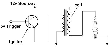
a little transformer coil .... magnetic fields and such.
[http://www.newmarket-transformers.co.uk/info/how-1.html]
[http://www.newmarket-transformers.co.uk/info/how-1.html]
Because the power the secondary pulls (and passes through the plug) comes through a 20ga wire, along with the power for the transistor in the igniter circuit.
Last edited by MazdaManiac; May 29, 2007 at 03:46 PM.

In the North American market (which is all we are concerned with here in this discussion), all of the terminology in the owners manual and FSM agree with conventional, North American usage.

Registered
Joined: May 2005
Posts: 300
Likes: 3
From: Eastern Ontario
MM:
Your triggering schematic on page 1 has the base and collector leads interchanged.
Your schematic on page 5 is also incorrect. As it stands, the base-emitter junction will be reverse biased when a five volt trigger is applied, so nothing will happen. It will work if you change the collector and base leads around, but then the base drive must go negative from +12 volts. A NPN transistor could be used but the drive would have to go to +12V if you wanted 12 volts on the coil. Alternatively you could use the 5V drive on the NPN but one end of the coil would have go to +12V and the other to the transistor collector.
Current through the secondary is so small that it will have virtually no effect on the current in the primary regardless of the wire size in the common parts of the circuit. In any event, the primary's job is virtually done by the time the secondary goes to use the connection. The outcome will depend on the size of the common wire as it affects the maximum current that can be drawn by the primary before the current is interrupted.
Registered
Joined: May 2005
Posts: 300
Likes: 3
From: Eastern Ontario
Well then let me be the first to congratulate you. If any of the circuits as drawn work as indicated, you should soon be receiving an invitation to accept your Nobel prize.
Seriously, MM, take another look.
Seriously, MM, take another look.
I don't know what to tell you.
I'm not an electronics guy, particularly.
I just grabbed the parts out of a bin, built the board, soldered them in and off I go.
I guess its plausible that they are actually PNP transistors and my cross reference is wrong (or I switched them up in a moment of foggy thought as I was testing), but other than that, there isn't a whole lot of possibility that anything else changed between my building that circuit and drawing that diagram.
I had tried JFETs as well, but they didn't work.