When you click on links to various merchants on this site and make a purchase, this can result in this site earning a commission. Affiliate programs and affiliations include, but are not limited to, the eBay Partner Network.
my recommendation would be to remove the t-stats in the OE coolers if that’s what you have and plug the bypass holes, then have a combo bypass/filter assembly and mount it up close to where the line comes out at the lower front oil cooler line. Like where the AC compressor used to be located or a support bolted on there with it down lower close to the feed source. . Thought we discussed that a long time ago by email.
If it’s a filter only assembly I’d still mount it on that same forward line before the first cooler to prevent anything that might come from the engine from getting to the coolers. If it’s a bypass filter and plugs though, it won’t prevent that. Which is why a lot of racing filters don’t have a bypass, but they instead have engine sensors and safety protocols in place to shut the engine down instead. Being on the OE pcm you would need to add all that through other means, like a dash display system, etc.
.
I have aftermarket coolers, so stock coolers and their thermostats don't need to be removed or bypassed. I agree with the preference to have the filter between the engine outlet and the first cooler.
I asked for other locations and you suggested the area where the AC compressor normally is. I haven't taken a look at the available space in that area. Why is that a good spot? Proximity to the engine outlet is an obvious one, but it doesn't shorten an oil line route. It would be more protected from tire interaction there.
Last edited by racer-tom; Dec 8, 2020 at 10:41 AM.
I have aftermarket coolers, so stock coolers and their thermostats don't need to be removed or bypassed. I agree with the preference to have the filter between the engine outlet and the first cooler.
I asked for other locations and you suggested the are where the AC compressor normally is. I haven't taken a look at the available space in that area. Why is that a good spot? Proximity to the engine outlet is an obvious one, but it doesn't shorten an oil line route.
well I wrote it twice and both times the webpage refreshed and wiped it out just as I was hitting submit. To just spit it out shortly to avoid strike 3, you�re a smart guy and a decision by committee isn�t necessary. Just do it however you think best fits your need and I�m sure it will be fine.
I put my remote filter on the frame rail horn, behind the driver's side oil cooler. I'm only running one (factory) oil cooler and it made for a very short run from the filter to the cooler and an easy hose route back to the engine. The lines themselves are -10AN and are P-clipped to the inside of the frame rail so it makes getting the engine installation and removal easy.
Different engine and all, but the oil feed and return are in the same spot, relatively speaking.
Just dropping a line with this great work! Awesome cage and the welds look solid! I noticed with your omp early on you didn�t have a sohn adapter, is this something you were going to add or are you just going to monitor oil levels and fill as needed? Amazing work and I wish you all the best bud, good luck and have some fun!
Thanks for the comments @Monstermills. With regard to the "missing Sohn adapter", I will be running the stock OMP with synthetic oil in the sump, and premix in every jug of gas that goes into the car. I also will be changing the oil often, so minimum issue with injecting oil from the sump.
I feel like I'm very overdue with lots of post, but again as I had some time during the recent holidays I opted to work on the car rather than posting updates.
This is my transitional post, moving from 2020 to 2021. I'll start off by saying that I realize how fortunate I am to be writing about a race car project that I'm now seeking to "finish". There are many positive things in my life and I'd like to note those before getting into the challenges in 2020 that prolonged my project.
I am employed, and have been throughout the pandemic to date.
I have a job that allows me to work from home, which I have done for the last 9 months.
The company I work for is thriving even in the current economic environment.
My immediate family is all healthy, and even had an addition this past year.
While I don't currently have a drivable track car, I was able to attend multiple race events in 2020 by way of my USTCC "weekend job".
The significant challenges in 2020:
That job I have at a great company had me working overtime days most of the year, leaving little time for work in the garage.
We did lose one family member quickly, unrelated to COVID-19.
My race trailer was stolen, along with my previous race car, significant spare parts, supplies, and tools that were in it.
So, at the end of 2020, I had a project that was "90% complete, with 90% of the work remaining".
Last edited by racer-tom; Jan 8, 2021 at 05:19 PM.
Long ago I intended to introduce myself, but instead dove into car build coverage instead. So, here that is.
By way of education, I've got an electrical engineering degree. My profession is project and program management in hardware and software development, and now marketing.
In terms of the car stuff, I started with autocrossing right after finishing college. I did that almost "over the top" for a year and a half in a slower stock class. Once I confirmed I was bit by the motorsport bug, I took the plunge and went through SCCA drivers school in a car I bought and prep'd for that purpose. I raced that car in Showroom Stock for a couple of years. Since I wasn't running away after that initial experiment I decided to invest in the next step while I was still young and unencumbered. I bought a new car from a dealership to run competitive in Showroom Stock. I competed with that car for 4.5 years in Regional and National races throughout the western state and went to the SCCA Runoffs twice at Road Atlanta. That car reached the end of its eligibility and the chassis was well worn. At about that same time I was ready to buy my first house, so I decided to scale back. From that point on I built and prep'd older modified road race cars at local races with occasional ventures out of state for events. In those early days I also connected with the beginning of NASA as one of their first instructors, then as HPDE school director for the founding region. Later I switched and took on the regional race director role.
After competing in a few more season championships, including a full endurance season and a couple of 12 hour endurance races, I decided to take a different tack. Rather than killing myself (the one man crew) to get the car ready in a rush for each next race of the season so I wouldn't miss out on any championship points, I thought it better to race occasionally and thoroughly enjoy those less frequent events. I also chose to pursue a long time dream to build a sports racer from scratch.
I chose a local builder's design and worked a deal to build my car in the back of his shop. I worked weekends and nights (often 9PM to 2AM) to get the car 90% done. Then, after selling two houses , getting married, buying a new house, and then having a child, that project got put on hold with the car literally getting pushed back into a corner. After about 5 years, life calmed down a bit and I re-engaged with the project which took a couple of steps backward before moving forward. I made progress back to 90% done and then life got in the way again. 5 year off, then re-engage, repeated. Eventually, 18 years after starting I got the car finished and on track.
Last edited by racer-tom; Dec 8, 2022 at 07:48 PM.
I did a handful of events, then the car needed some additional fab and fiberglass bodywork. I struggled to get motivated to finish those repairs. I had also come to the realization that me and my one man crew was not well suited for working as race director (or whatever) and then being able to hop in the race car and get on track. It required more work and prep at the track (even just the time needed to get strapped into the car and get ready), than my event situation supported.
Last edited by racer-tom; Jan 6, 2021 at 03:30 PM.
While working the 2019 NASA Championship at Mid-Ohio as race director for Group A, I finished my sole searching and decided that going back to a sedan would suit me better. I then I thought about what class and type of car I would enjoy building and driving. Having positive history with rotary engined cars (previously owning an RX-7 GSL-SE and being involved with the NASA Pro-7 race series), I decided to build an RX-8.
I watched Thai's race (below) at that event, but didn't get to meet him.
Last edited by racer-tom; Jan 6, 2021 at 07:26 PM.
Reason: Added photo
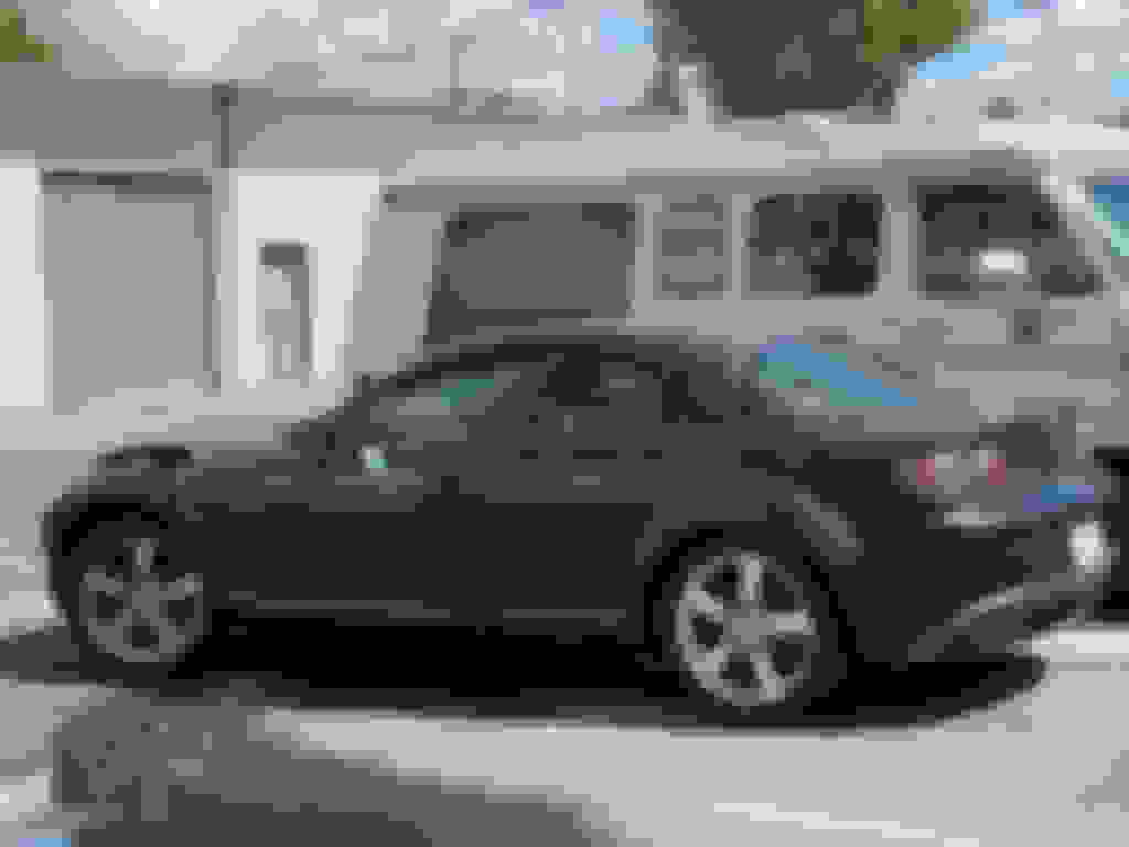
I previously showed the project car that I bought, but it's a bit amazing to me to look back and see how quickly I acted and moved forward, because I'm almost never an impulse buyer. I flew home from the NASA Championships on Monday and 6 days later I bought this car.
Tom, for me this is the most gracious and inspirational series of posts the RX8Club website has likely seen in a long time.
Thank you for reminding us of how important it is to be mindful of the big picture in life and always thankful of those things around us often taken for granted, especially during a challenging period of time such as this when it’s so easy to be discouraged and distracted from them.
.
I talked to a friend and did some research and determined that the Series 2 transmission was what I would want to run, and the Series 2 final drive ration was preferential to the Series 1. So, I kept an eye out for how much they were selling. Also, for a few years I had been looking into various salvage and other insurance type auctions. During one of those periods of time occupying oneself with random site browsing, I saw that one of my saved car searches identified a 2010 RX-8 and best of all it was at an auction site very close to me.
I knew that I needed to have the required reseller/salvage license to bid, or have an agent do it for me. I contacted a friend who had the right credentials. We discussed the situation, and agreed upon a max amount for the online bidding. Auction day was exactly 1 month after I bought my 2004 project car. We won the lite action with a bid of $900. All in with various fees, it cost me $1,400. They give you a certain amount of time to pick up the car (something like 3 days), so I retrieved it 2 days later.
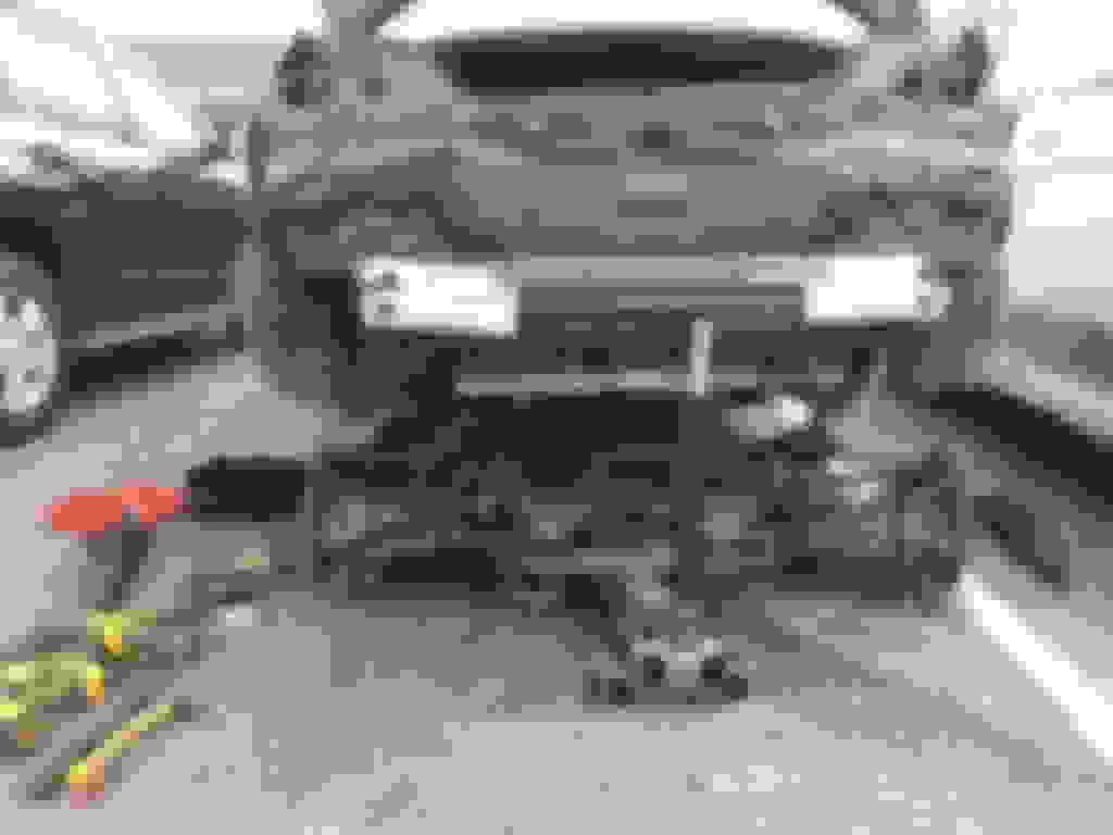
While the project car was off getting its roll cage installed, I worked to removed desired parts off the 2010 car. I literally stripped it down to the bone, and then some. I even found a guy that bought the front and rear subframes and their unibody mounting point which he cut out of the shell. He planned to use those and the suspension which he also bought to convert into a Datsun 240Z (which had already been "bastardized", so was no longer pure).
The interior has scrap metal and other rubbish to dispose of with the shell. I even removed the windshield, as the one in the photo is the remains of my failed attempt to cleanly remove the one from my 2004 car.
Harbor Freight moving dollies worked pretty well in the driveway, but not as well in the transition to the street and onto the awaiting trailer.
Last edited by racer-tom; Dec 8, 2022 at 07:56 PM.
Tom, for me this is the most gracious and inspirational series of posts the RX8Club website has likely seen in a long time.
Thank you for reminding us of how important it is to be mindful of the big picture in life and always thankful of those things around us often taken for granted, especially during a challenging period of time such as this when it’s so easy to be discouraged and distracted from them.
Thanks Mark.
This is a quote that I posted under my bio section on a website many years ago:
"... often the the real hero is the guy who puts his racing urges aside and concentrates on mowing the lawn, taking his kid to a Little League game and spending the extra dollars on the family." Tim Suddard in the July 2002 editorial of Grassroots Motorsports.
and back to our regularly scheduled program = car build stuff ...
Here I'll share a bit of info and technique for anyone wanting a similar mod, but not knowing how to tackle the task.
The cooling system: In stock configuration, it has a conventional thermostat with integral bypass blocker. Many people feel that it's beneficial to remove the thermostat from the cooling system. Even in it's designed open state it represents a restriction in the water flow, and the part can fail which offers a reliability issue. I offer a basic explanation of how the stock system works with and without a thermostat installed.
This image is rotated to align better with the diagrams below.
Situation 1: Water from the engine core is below the opening temperature of the thermostat. Therefore, the thermostat block the water flow up and left to the top of the radiator. At the same time the "plunger" on the thermostat remains in its relaxed position which leaves the bypass route to the inlet open so that still cool water can return to the engine core.
Situation 2: The water from the engine core (orange) has now reached the opening temp of the thermostat. This allows the warm or hot water to flow through the thermostat up and to the left to the top of the radiator. At the same time, the "plunger" on the bottom of the thermostat moves down (green arrow) and closes the bypass path to the inlet. This allows only the cool water from the radiator (blue) to return to the engine.
Situation 3: Thermostat removed for "performance enhancement". While the thermostat is no longer restricting water flow to the radiator (orange arrow), it is also not there to block off the undesired bypass path (red arrow).
So, if one wants the thermostat removed for the benefits described earlier, one needs to block off the bypass path.
So, this is how I blocked off the bypass and removed one of the inlet port and plugged it as well.
First a look again at the thermostat housing. The housing is sitting on the ground as if the ground were the front engine cover plate. On the right is where the thermostat itself would sit. The red arrow shows the area of the internal bypass from the engine inlet area leading to the engine return area.
The three ports on the left are the radiator return (on top) and the return from the heater core and the inlet from the expansion tank (with the red X on it).
This is looking straight down the housing through where the thermostat is normally installed. The dark hole in the center is the top of the bypass path. This is what will be tapped and plugged to block the bypass path.
Here the port pipe (that previously had the red X) has been cut off. I'm going to use the remaining original heater core inlet pipe for the return from the expansion tank because I like the orientation of it better. Since my heater core has been removed I don't need the other inlet pipe. That's why I'm removing the one with the red X.
The inlet pipe is press fit into the housing and was rather tight. I cut slits down the wall of the pipe to allow it room to collapse inward a bit.
I tried an EZ-Out remover, and this loosened it up a bit.
I then used ViseGrips to grab the external portion and was able to twist it out.
Both the bypass path hole and the port pipe hole had the same inner diameter. I used a 1/2" NPT tap to create tapered threads in both holes. I don't remember if I had to increase the ID of the holes first to be the size that the tap wanted.
Here you can see the tapping of the bypass complete, since the tap threads are all the way into the hole at this point. You can see that I decided it was best for me to mount the housing to an engine while performing the tapping (since I had one available).
It took quite a bit of force and leverage to work this large of a tap. You can see the housing in it's normal position on my extra S2 engine core.
The is the tap barely started into the front inlet where I removed the pipe.
Again the leverage needed to tap this.
The resulting tapped threads in the front port hole.
Fresh threads with a hardware store pipe plug in place. Functional, but ugly.
This is a top view, similar to earlier, looking into the bypass path. Better light, but poor focus, showing the new threads.
Again a hardware store pipe plug in place.
Besides being ugly, this style plug sticks up and is in the path of the water flow. So, instead, its better to use internal allen head plugs that can sit flush with the external surface of the hole in the housing.
I didn't get a photo of the allen head plug in the bypass path, but you can see the difference here on the plugged front port hole.
I'm trying to open up the airflow behind the radiator as much as possible. For me, this mean removing the stock air filter housing / airbox, moving the battery (to a location for better weight placement as well), and moving the cooling system expansion tank.
With the purchased of other parts I acquired a slightly used aluminum expansion tank. This tank was made to replace the stock expansion tank in its original location. My initial thought was to locate it on the firewall in the area where the windshield washer tank was, since I won't be running one of those.
The spot seemed okay even using one of the factory studs I had left on the firewall for the right side mounting hole. I'd have to fab a bracket to mount the left side.
I verified that the height would clear the hood when closed. However, I didn't like the way the inlets were pointing. I could cut those and get ones welded on in the orientation and direction that I wanted, but I also didn't like how it was off in the corner with three hose having to be routed a long way to get to it.
So, I considered other locations closer to where it was needed. On some formula cars and sports racers the "swirlpot" is actually mounted right on the engine block. I targeted the area inside the right shock tower. I tried the tank I had in hand, but it was a bit too big and awkward for what I was trying to do. So instead I took some measurements and ordered parts against this plan
A simple tank with a cap neck and overflow on top, a threaded bung on the side, and a larger thread bung on the bottom, with mounting tab welded on the back.
This is what I ended up with.
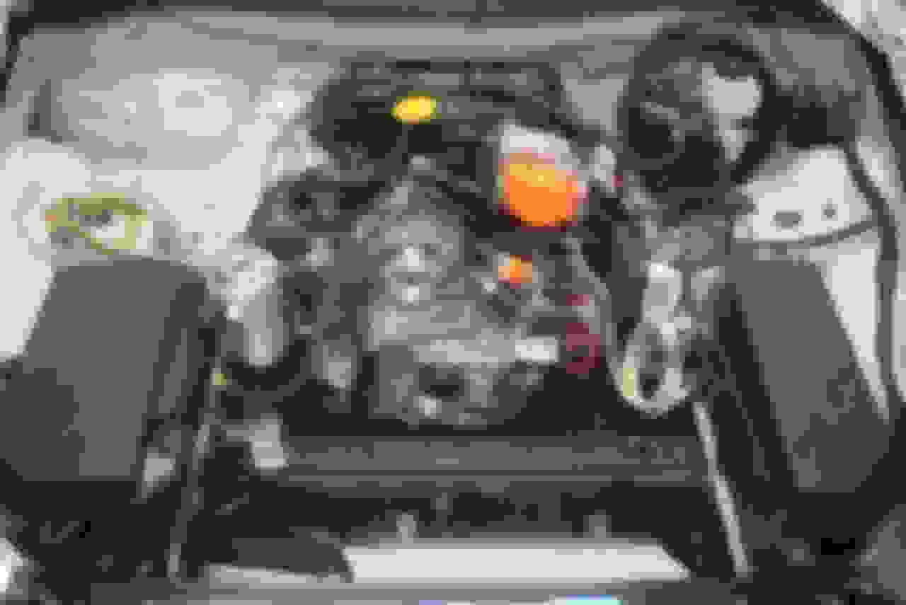
The tank fits nicely to the left of the thermostat housing.
(Side note - the coil of wire wire on the right is a temporary connection of the alternator to the fusebox.)
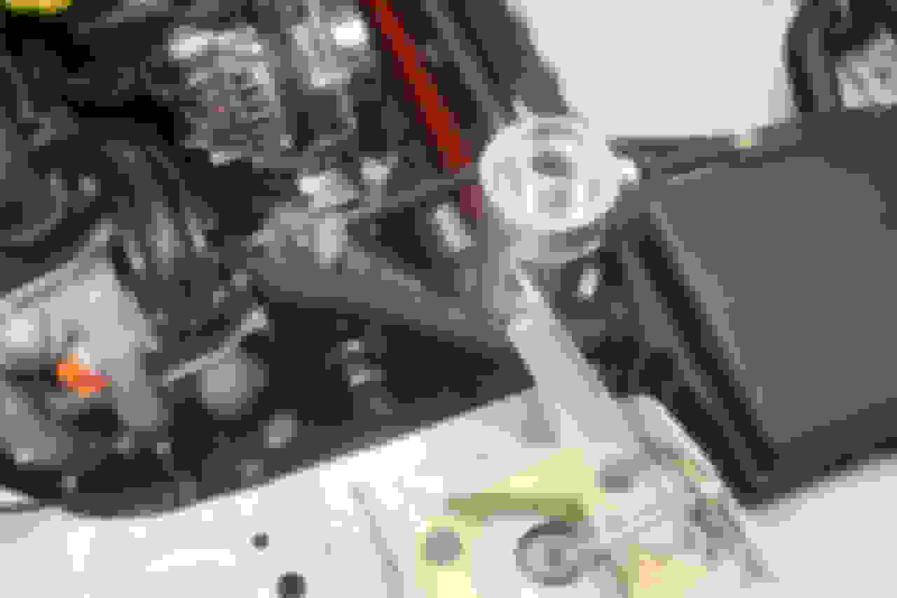
The main mount is via aluminum angle to the shock tower.
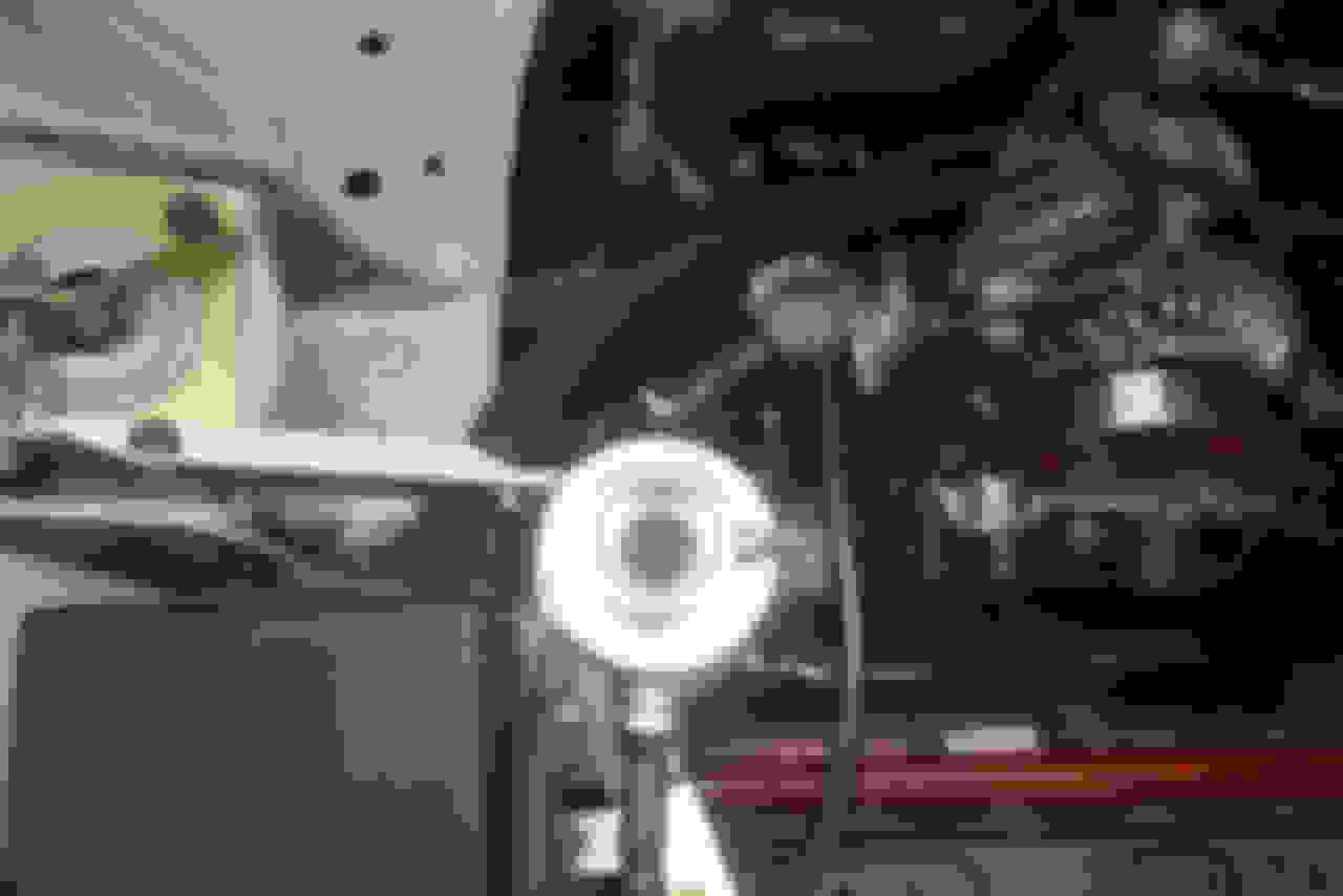
There is supplemental support via a mount on the side of the PCM box.
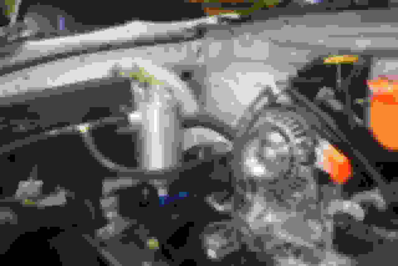
The radiator vent and thermostat vent hoses join at a tee, then go to the side of the tank. The tank returns water from its bottom via the blue hose barb to the thermostat housing via a very short elbow (not in place in this photo). I just noticed it looks like a large black serrated hose is coming from the back side of the tank, whereas that is actually the wiring harness traveling from the PCM box to the engine just behind the thermostat housing. It can be seen better in the previous photo.
At the time of these photos [New Year's Day 2021], the 5/8" ID hose was on order, as well as the lined hose clamps for all of the connection. I'll be running a Stant racing cap (18-22 PSI), and the overflow will route via hose to a catch tank. Somewhere I have an aluminum bicycle water bottle I'll likely use for this (once I find it) and likely mount it along the inside of the shock tower.
Last edited by racer-tom; Dec 8, 2022 at 08:12 PM.
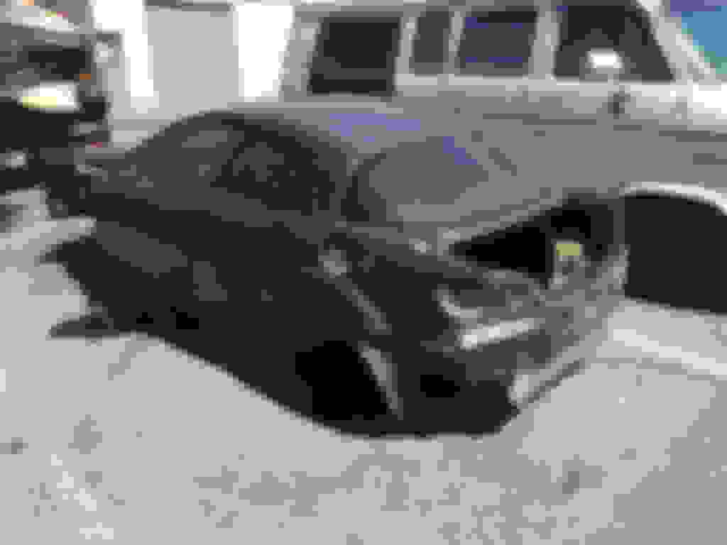
Since I sold off the Mazdaspeed bumper that came with my original project chassis, I was on the lookout for a cheap stock front bumper in reasonable shape. I happened upon an ad by a very local guy that was parting out this car which was the same color as mine - dark green.
I bought a few key items i needed/wanted, then ended up stripping a lot more stuff off if before he had it hauled away for scrap.
I wanted the differ pumpkin for my 5.12 ring and pinion, and ended up with spare everything suspension and axles. I could have taken the subframe, but didn't have room for it. Yes, this was a one man job in a parking lot.
Likewise, I wanted to take the 4 complete doors, but didn't have room for them. This is how the shell looked when I'd had enough of it.
That's how I ended up with 2.5 car which I've been selling off many parts to offset the cost of my race car project. Helping people and being fair on parts I sell is not only good Karma, but happy buyer are occasionally return "customers". This guy bought several parts from me awhile back to repair the front and right corner of his Series 2 RX-8. He returned today to buy my engine core to tear down, and start a rebuild. The friend who came to help load it in their car also wants to buys parts from me now.
Last edited by racer-tom; Jan 10, 2021 at 12:33 AM.
This is what I had fun with yesterday. While the car is not an Rx-8 or even an rotary, the format of the race is a different fun one. Handicap racing, also known as Australian pursuit. Similar concept to bracket drag racing, but applied to lap times, then multiplied by the number of laps.
Each entrant submits their lap time. Each lap time is multiplied by the number of planned laps for the race (10 in our case yesterday) to get each entrants overall race time. The driver with the slowest lap time, and therefore the longest overall race time starts first. Each of the faster drivers starts delayed such that their overall race time will have them finishing at the same time as the first driver's calculated finish. If anyone "breaks out" by going faster (on average) than their submitted lap time, they are disqualified.
So, the finish order of drivers (who don't break out) at the checkered flag is the race results. For the race, no clocks or timing devices, or communication devices are allowed in the cars. Each driver can only have one pit board. One of the great aspects is that the raw speed of the car doesn't matter at all - horsepower, weight, tires, none of it. It comes down to driver consistency, strategy, driver-crew pit board teamwork, and some luck. At yesterday's inaugural race we had 11 starters, and I finished in 2nd place. My lap times in the race? I don't even know. I just know I didn't break out.
1997 Honda Civic 1.8L, 205 WHP (if that much), 2480 pounds. I ran on Hankook street tires, because - well - it didn't matter.
https://www.facebook.com/drivetracktime at https://www.thunderhill.com/ in Willows, California.
Last edited by racer-tom; Dec 8, 2022 at 08:16 PM.
Fun fact: the factory service manual lists the wrong torque spec for the eccentric shaft pulley bolts, if you use what they show for ft-lbs. Don't ask me how I know this < head slap >
at least they used a lightweight aluminum soda can ...
I would suggest that further minimizing hot pre-radiator fluid from the pump suction inlet might be best.
Such as mounting it up high on the firewall, bringing the t-stat vent into the side, and then plumbing the bottom back to the radiator vent rather than into the pump inlet side (not good for racing, I would have blocked off both). Adding a tee line between the side and bottom connections might be needed if you can’t get the bottom connection higher than the radiator vent connection.
.
@TeamRX8 I was so tired and brain dead when you posted the message above that I had to come back to it later. Even then, I took me a while to understand what you were pointing out. In the end, I agree with your suggestions for an optimum setup, but I feel that my configuration (with one small change) will perform sufficient for my goals.
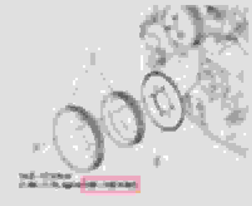
While thinking about my hoses and routing, I remembered a subtle detail within the factory hose going from the thermostat vent to the expansion tank
A couple of inches from the end, Stuffed down inside the hose, is a flow restricter.
Here I've pulled the restricter to the end of the hose, so it's only starting to protrude. The restricter is essentially a brass bead. The outer diameter of the bead matches the inner diameter of the hose, and the center hole determine the amount of water flow. The 7/64" drill bit was used to measure the center hole diameter.
Here I'm comparing the bead's 7/64"D center hole (on the right) to the Inner diameter of the end of the brass tee (on the left). The ID of the tee is 17/64"D. Since area = pi * R squared, the restricted area is only 17% of the original.
So, I inserted the brass bead between my hose tee and expansion tank. So, as I installed it, it will restrict the water flow from both the thermostat vent and the radiator vent.
For the casual reader: The purpose of the expansion tank is to be the highest point of the cooling system so that air pocket don't exist in other locations. To achieve this, the highest locations of the engine (the thermostat housing) and of the radiator are connect to the tank which should be higher than both. In this way air at either location has a path to the higher reservoir. As Team mentioned, the expansion tank doesn't need to return water from its reservoir to the water pump inlet. However, allowing some flow through the tank will help evacuate air from the other area of the cooling system.
Last edited by racer-tom; Dec 8, 2022 at 08:21 PM.
Since I was dropping my rear subframe, it was an ideal time to finally finish up the work I had previously started on the rear emissions evap system.
With some warm weather, I felt like making some progress at the rear of the car.
Having a few jack available make this one man job easier. I lowered the subframe along with full suspension onto the rear wheels. The rear springs/shock had previously been removed during interior painting.
Quite a long time ago Team provided info and his suggestion on how to deal with the rear emissions evap charcoal canister and hose routings. I'm repeating his image here for local reference.
Removing the large charcoal canister was one of the goals. The other was dealing with the eliminate vent line from the engine.
I had already removed the air filter before seeing Team's recommendation and this diagram. The front of the car is to the left in these diagrams.
This is the area above the differential and subframe. The front of the car is at the bottom of this image. As I mentioned, I had previously removed the air filter, which left the hose in the top left hanging freely.
This is a similar view with the air filter re-installed. The corrugated hose going to the four way tee will be removed. The other end of that tee has a large and small hose going to the gas tank vents. The small hose going to the left is connected to the gas tank filler neck.
Since it wasn't initially clear how to deal with this, I first chopped off the corrugated hose where it looked like it joined the tee fitting.
I then realized that the end of the corrugate hose was slipped over a barb end of the tee. So, by slitting the hose along one spot along the length of the barb, I was able to removed it from the barb.
Then, as Team's diagram showed, I used the original hose that was connected to the air filter to connect from the filter to the tee barb. One additional note is that rather than just rotating the hose so it lined up with the brag, I installed the hose with reverse orientation. The filter end went to the barb and the other end was put on the air filter. I did this because the angle and lengths worked out better. (LOL: I just noticed that you can see my garage TV in the lower left corner)