When you click on links to various merchants on this site and make a purchase, this can result in this site earning a commission. Affiliate programs and affiliations include, but are not limited to, the eBay Partner Network.
I will be happy to explain how to wire them properly with full dwell/output capability, just to prove how FOS many of the replies here are, as well as provide the info on where to buy the harness
One of the features I appreciate most is that these coils use a standard 90 deg HEI coil boot that plugs on and off easily and allows the wires to be bought/replaced at nearly any auto parts store for minimal cost in an emergency situation.
TeamRx8, can you do a write up on how to wire them properly, with full dwell/output capability? and any additional information that might be needed. That would be greatly appreciated.
If you either don't understand or grasp this please seek help from someone else rather than contacting me; use at your own risk, blah-blah-blah ....
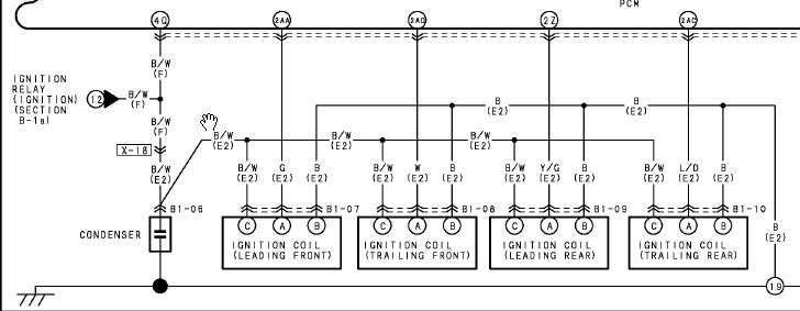
OE Coil wiring harness layout:
WARNING: DIAGRAM BELOW FOR DEMONSTRATION PURPOSES ONLY! Please obtain the correct Mazda RX-8 model year electrical manual for your vehicle to confirm the proper OE harness pin connections. Some model years are different than others.
Based on the demonstration diagram above you need to make piggyback harness as shown below. However, the OE pin connection may vary between certain Mazda RX-8 model years. Please do not copy the OE Pin A and Pin B connections below without verifying it for your model year. The OE pin from the PCM must connect to Pin A on the IGN-1A coil and the OE ground pin must connect to pin B. Some model years have been reported to be reversed as compared to the demonstration diagram.
Take care of the warning Team provided regarding pins D-E. You want to use at least a 12awg wire for those pins as that should be sufficient to carry 20A+/-
Last edited by paimon.soror; 01-22-2015 at 02:39 PM.
Reason: Corrected my typo of C-E to D-E as C.Ludwig mentioned
Take care of the warning Team provided regarding pins C-E. You want to use at least a 12awg wire for those pins as that should be sufficient to carry 20A+/-
Pin D and E and primary ground and positive. They're the two wires you need to ensure are up to task.
The coils have a 19A driver, so everyone assumes they pull 19A all the time. With a 4.5ms charge time, a set of 4 will pull around 5A at idle and ramp up to around 8-10A at high revs. You'd need to dwell the coil incredibly hard to actually pull the limit of the driver.
I ran them happily for 15k miles never had a missfire or issue. Currently working on re-installing them. 20A is overkill unless you are running high dwell, I ran mine off the 15A ign circuit and never popped a fuse or any other issues. You are only going to run into the 19A max current at max dwell of 9ms anything less will be much less current. Might even be able to run them off the stock harness wires, but that would be pushing it...
The smaller wiring is likely valid as long as you don't get crazy on setting dwell. So alternatively you could wire the RX8 coil wire C to IGN-1A coil terminal E
the info in my possession (from a bench test):
3.5 mS - 4.50A...........65mJ
5.0 mS - 8.00A.........130mJ
6.0 mS - 12.5A.........160mJ
As you can see above the output energy relative to dwell/input current draw starts tapering off. Around 4.5 - 5.0mS @ 12V seems to be a good range to shoot for. Be advised you have to adjust dwell accordingly relative to voltage per the ignition map.
A linear calculation will typically work well. So if your goal is 4.5mS @ 12V it goes like this:
4.5 mS x [12V/(alternate V)] = equivalent dwell setting
For 14.0V equivalent dwell = 3.85 mS
For 11.5v equivalent dwell = 4.69 mS
The above information about my IGN-1A coil is correct WHEN one understands the EXACT case.
When Mercury Racing specified this coil, they stated an EIGHT AMP feed@14 volts.
This testing was performed by Mototron after some Mecury Racing engineers left to create their own division, Mototron, which has now been absorbed Woodward.
When a greater AMP feed is used, the output will be greater, ALMOST 280 mj@8.8ms.
A LARGER dwell will FRY the fitted internal IGBT as the coil is SATURATED, a"dead" short.
NOW, spark duration is ALSO changed by items under Ohm's Law.
#1 Plug Gap effects spark duration, smaller=longer arc
#2 Plug Wire resistance, higher resistance=longer arc
#3 RPM of engine, HIGH RPM lower Arc Duration requirement.
#4 RPM of engine, LOW RPM longer Arc Duration requirement
I think sometimes the duplication of threads about the same subject can be confusing.
New members, or not so new in my case, look for answers about subjects and it can be difficult to sift through them to get coherent answers.
I believe long time members forget that what passes for common knowledge after a while is all new to recently joined members.
It's hard to get good info without investing a lot of time reading through myriad responses and contrary opinions.
It's why I try to help some within the limited scope of my knowledge and hesitate to bluntly tell new members to search.
I know I'm bumping this from beyond the grave, but what is the final word on these coils? I was looking at the sakebomb kit which looks quite nice, but I want to see if any real world testing has been completed.
I know I'm bumping this from beyond the grave, but what is the final word on these coils? I was looking at the sakebomb kit which looks quite nice, but I want to see if any real world testing has been completed.
No actual testing that I'm aware of.
I have it, installed in March, 8k miles.
I like it, but I can't say if it's better than any other.
As someone who has been shocked by these and other ignition coils, I can say with certainty that they light your butt up more than twice the amount of the leading competitor.
if you want it to work, assuming it really does anyway, you don't want anything under it for sure. I doubt having a grounding lug on top would matter, but can't say that I know 100% for sure.
I don't intend to use the KS on my current engine once it's up and running.
Finally got motivated to do this. I don’t need high dwell for NA and decided to build a direct-connect adapter harness rather power from the battery. The D585 coils max out at 7 amps, so the IGN-1A should bo ok up to the mid 3mS dwell range. Which 3mS will still produce more than double the truck coil output. This is more than adequate and also not pushing excessive heat loading etc. through these heavy duty coils. Also, watch out for cheap copycat overseas versions of these coils. You can search the web for more info on that.
This is the Rx8 harness adapter connector needed; Sumitomo 3-way:
And i picked up a set of four 12” long IGN-1A pigtails off fleabay for $34 shipped for convenience since I don’t already have 5 different color coils of wire in the appropriate size.
a company called Rotary Werks in south Florida sells this direct-connect harness for $150 for anyone who wants to buy it rather than make it. However be advised if you run high dwell that the 15A IGN fuse is going to blow and possibly burning up engine harness wiring too under an extreme situation.
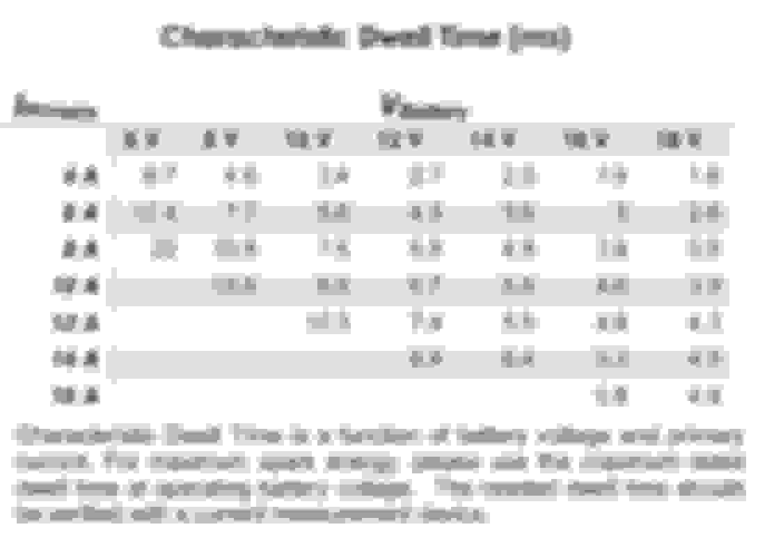
Dwell vs Amp vs Voltage chart I found on the RaceGrade IGN-1A coil literature
looks like you could probably run up to 4.5ms dwell and still be ok for a direct-connect harness, but unless you have a turbo and are having misfires it isn�t necessary to push them that hard. Though people posted on RX7Club that the coil barely even gets warm running at 4.5mS dwell.
Note that IGN-1A coil connector Pin C on the diagram above does need be grounded well to the spark plug surface; rotor housing for us, to deliver the full discharge output energy. On Rotor 1 the unused knock sensor boss is the perfect spot. On Rotor 2 just putting the lug between the bolt head and the knock sensor should be fine as somebody had asked in an earlier post, assuming you are using the knock sensor/have it mounted.
No actual testing that I'm aware of.
I have it, installed in March, 8k miles.
I like it, but I can't say if it's better than any other.
Came across this while perusing the recent posts here so I thought I'd update.
I installed the SakeBomb IGN-1A kit 03/15/2016, approx. 53,000 miles.
Now at 97,000, that's 44,000 on this kit, give or take a few hundred.
Problem free, I'm very satisfied with it.
TeamRX8 whats your take on the duty cycle requirments of these coils? AEM lists maximum 40% duty.
Would you limit dwell based on rpm?
40% duty cycle only applies to using the maximum 9 mS continuous dwell setting.
Base Dwell: 3.0 mS
Max Continuous Dwell: 9 mS but don�t exceed 40% duty cycle
Max Intermittent Dwell: 80% duty cycle, 5 seconds maximum
Mating Connector: Packard/Delphi 12162825 �Pull to Seat�
Mating Contacts: Packard/Delphi 12124075 �Pull to Seat�
High Tension Wire Terminal: HEI �spark plug top� Style
An NA Renesis generally won�t need to exceed 3.5 mS with 2.5 - 3.0mS likely being more than enough. Not near the max duty cycle for continuous or intermittent dwell per the spec info above. I seem to recall that 80% duty cycle at 10,000 rpm is around 4.8mS? Might need to double check my memory.
Thanks for pointing that out TeamRx8. So it looks like you can run them at higher duty as long as it isn't for too long. Probably to avoid heat build-up. I calculate 80% duty at 9000rpm you would need a bit over 5.3mS so they can be run much harder than the settings I currently run to meet 40% duty not that they need it.
Well someone was asking me about the importance of two grounds and where they mount in a PM. I thought it would be beneficial to post it here with some minor edits. In this case he has a SakeBomb harness that allows full dwell/output potential with a dedicated power-wiring configuration to the battery:
The only thing that is kind of confusing is that there is a chassis/battery ground and coil ground (to rotor housing). Since the motor is grounded to the chassis, I don't really see why I need two different grounding locations???? Just seems weird.
Because they won’t operate optimally unless the grounding is correct. Remember, the IGN-1A can output 3x+ more energy than a D585 coil and more than double anything else. Which the D585 only having a single ground is very particular about too. On some things you can have an ok, but not solid, ground and will get by, but not these coils.
The two separate grounds represent how the coil is designed and operates; which is essentially two electrical circuits. The battery ground (recommended over chassis imo) is for the coil energy fill circuit. So the coil must first fill freely and without restriction to reach capacity. A weak ground is a restriction to filling the “bucket” quickly and fully; which is being filled directly from the battery. So grounding back to the battery negative post ensures that circuit is direct and complete. Then, the second circuit is when the coil fires and dumps that “bucket” of energy to the spark plug lead. In order for it to jump across the gap at max output the grounded side of the spark plug; the housing, needs a good solid connection not to impose a restriction for that part of the other circuit.
So like a performance engine; you don’t want a restriction on the intake in order to fill the fill the compression chamber with energy, but then you also don’t want any restriction on the exhaust side either or the engine won’t output at maximum potential. When the grounds are weak the coil will lose efficiency and build heat. I’d strongly recommend doing what you have to to ensure these connections are solid and to the points recommended. The end result will be a dead-solid ignition system that is reliable and can fire off anything you throw at it.

 10-05-2013, 11:11 PM